

Thunderbolt ThunderBox 400 Quick Start Manual
ThunderBox 400
(Thunderbolt/USB 3.0 to 6Gb/s SATA RAID Storage)
Quick Start Guide
Version: 1.1
Issue Date: January, 2014
Thunderbolt™ Prod
uct

Copyright and Trademarks
The information of the products in this manual is subject to change
without prior notice and does not represent a commitment on the part
of the vendor, who assumes no liability or responsibility for any errors
that may appear in this manual. All brands and trademarks are the
properties of their respective owners. This manual contains materials
protected under International Copyright Conventions. All rights
reserved. No part of this manual may be reproduced in any form or by
any means, electronic or mechanical, including photocopying, without
the written permission of the manufacturer and the author.
FCC Statement
This equipment has been tested and found to comply with the limits
for a Class B digital device, pursuant to part 15 of the FCC Rules.
These limits are designed to provide reasonable protection against interference in a residential installation. This equipment generates, uses,
and can radiate radio frequency energy and, if not installed and used
in accordance with the instructions, may cause harmful interference to
radio communications. However, there is no guarantee that interference will not occur in a particular installation.
Manufacturer’s Declaration for CE Certication
We conrm ThunderBox 400 has been tested and found compliant with
the requirements in the council directive relating to the EMC Directive
2004/108/EC. Regarding to the electromagnetic compatibility, the following standards were applied:
EN 55022: 2006, Class B
EN 61000-3-2: 2006
EN 61000-3-3: 1995+A1: 2001+A2: 2005
EN 55024:1998+A1:2001=A2:2003
IEC61000-4-2: 2001
IEC61000-4-3: 2006
IEC61000-4-4: 2004
IEC61000-4-5: 2005
IEC61000-4-6: 2006
IEC61000-4-8: 2001
IEC61000-4-11: 2004

Contents
1. Installation .................................................................. 4
1.1 Before installation .............................................................4
1.2 Summary of RAID Storage Setup Steps ................................5
• For Mac OS X ...................................................................5
• For Windows ....................................................................5
1.3 RAID Storage View ............................................................7
1.4 Locations of the Storage Component ....................................8
1.4.1 Drive Tray/Status LED Indicators ....................................8
1.4.2 LCD Panel LED Indicators ..............................................9
1.4.3 Thunderbolt Port LED Indicators .....................................9
1.5 Setting Up RAID Storage .................................................. 10
1.5.1 Physically Install RAID Storage and Drives ..................... 10
1.5.2 Mac Users ................................................................. 15
1.5.2.1 Install the MRAID Software ..................................... 15
1.5.2.2 Congure RAID Volumes ......................................... 19
1.5.2.3 Format RAID Volumes ............................................ 22
1.5.2.4 Make A Bootable RAID Volume ................................ 23
1.5.2.5 Unmounting RAID Volumes ..................................... 24
1.5.3 Windows Users .......................................................... 24
1.5.3.1 Install the MRAID Software ..................................... 24
1.5.3.2 Congure RAID Volumes ......................................... 29
1.5.3.3 Format RAID Volumes ............................................ 32
1.5.3.4 Unmounting RAID Volumes ..................................... 32
2. Specication .............................................................. 34
2.1 Overview ....................................................................... 34
2.2 Features ........................................................................ 35

INSTALLATION
4
1. Installation
This section describes how to install the ThunderBox 400 Thunderbolt
RAID storage with host computer and disks.
1.1 Before installation
Thanks for purchasing the ThunderBox 400 as your RAID data storage. The following manual gives simple step-by-step instructions
for installing and conguring the ThunderBox 400 RAID storage.
Unpack
Unpack and install the hardware in a static-free environment.
ThunderBox 400 RAID storage is packed inside an anti-static bag
between two sponge sheets. Remove it and inspect it for damage.
If the ThunderBox 400 RAID storage appears damaged, or if any
items of the contents listed below are missing or damaged, please
contact your dealer or distributor immediately.
Checklist
• 1 x ThunderBox 400 4-bays RAID storage unit
• 1 x Installation CD – containing driver, relative software, an
electronic version of this manual and other related manual
• 1 x RJ-45 LAN cable
• 1 x Power cord
• 1 x USB 3.0 locking screw cable (USB 2.0 compatible)
• 16 x Drive mounting screws (4 per drive tray)
• 1 x Quick start guide
System Requirements
• Computer with Thunderbolt/USB 3.0 connector
• Mac OS X 10.6.8 or higher
• Windows 7, Windows 8
• Thunderbolt cable

INSTALLATION
5
1.2 Summary of RAID Storage Setup Steps
• For Mac OS X
Step 1. Physically Install the Hardware (Chapter 1.5.1)
1. Install HDDs.
2. Connect power cord.
3. Connect Thunderbolt cable.
Step 2. Install the MRAID Software Package (Chapter 1.5.2.1)
1. Download the install_mraid installer from the website at
“http://www.areca.com.tw/support/s_ thunderbolt/thunder
bolt.htm”.
2. Double-click on the install_mraid zipped le.
3. Double-click on the install_mraid icon on the Finder.
4. Follow the installer on-screen steps to complete the installa tion.
Step 3. Congure RAID Volumes (Chapter 1.5.2.2)
1. Double-click on the “MRAID” icon on the desktop.
2. Double-click on the “ArcHTTP64”.
3. Locate “Web Management” and launch
the McRAID storage manager.
4. Login User Name “admin” and the Password “0000”.
5. Click on the “Quick Create” to congure the volume.
6. Follow the on-screen steps to complete the conguration.
Step 4. Format RAID Volumes (Chapter 1.5.2.3)
1. Mac OS X recognizes that a new disk is available.
2. Follow the Disk Utility on-screen steps to initialize and parti-
tion your unit.
3. Icons for each new partition show up on your desktop.
4. They are now ready to use.
• For Windows
Step 1. Physically Install the Hardware (Chapter 1.5.1)
1. Install HDDs.
2. Connect power cord.
3. Connect Thunderbolt cable.

INSTALLATION
6
Step 2. Install the MRAID Software Package (Chapter 1.5.3.1)
1. Download the install_mraid installer from the website at
“http://www.areca.com.tw/support/s_ thunderbolt/thunder
bolt.htm”.
2. Double-click on the install_mraid zipped le.
3. Double-click on the “setup.exe” unzip le.
4. Follow the installer on-screen steps to complete the installa tion.
Step 3. Congure RAID Volumes (Chapter 1.5.3.2)
1. Double-click on the “MRAID” icon on the desktop.
2. Double-click on the “ArcHTTP64”.
3. Locate “Web Management” and launch
the McRAID storage manager.
4. Login User Name “admin” and the Password “0000”.
5. Click on the “Quick Create” to congure the volume.
6. Follow the on-screen steps to complete the conguration.
Step 4. Format RAID Volumes (Chapter 1.5.3.3)
1. Click “Start” ==> right-click “Computer” and select “Man-
age”.
2. Click “Disk Management” in the left pane.
3. Scroll down to the bottom of the middle pane. Windows will
dis-play a list of new drives attached to your system with a
label such as “Disk 1” or “Disk 2”, etc.
4. Right-click on the drive you want to partition and then again
to format it.
5. Once it’s formatted, Windows automatically assigns the next
available drive letter to it and then it will appear in Windows
Explorer.
6. They are now ready to use.
INSTALLATION
7
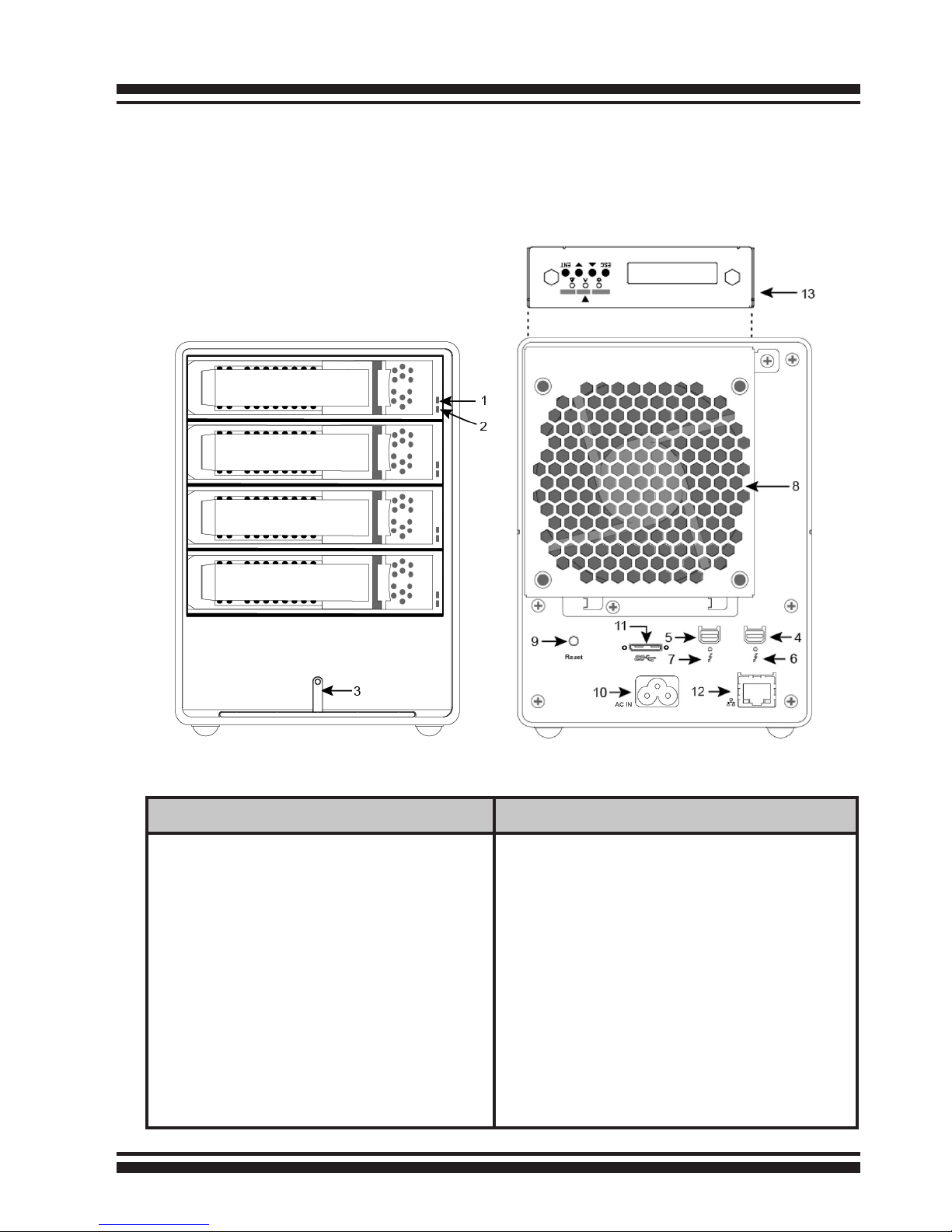
1.3 RAID Storage View
The following diagram is the RAID storage front view and rear view.
Front View Rear View
1. Disk Activity LED
2. Disk Fault / Link LED
3. Power and Global Fault LED
4. Thunderbolt Port1
5. Thunderbolt Port2
6. Thunderbolt Port1 Link LED
7. Thunderbolt Port2 Link LED
8. System Fan
9. Reset Button
10. Power Connector
11. USB 3.0 Connector
12. LAN Port
(For McRAID Web Manager)
13. LCD Panel with Keypad
INSTALLATION
8
1.4 Locations of the Storage Component
The following components come with LEDs that inform ThunderBox
400 RAID storage managers about the operational status.
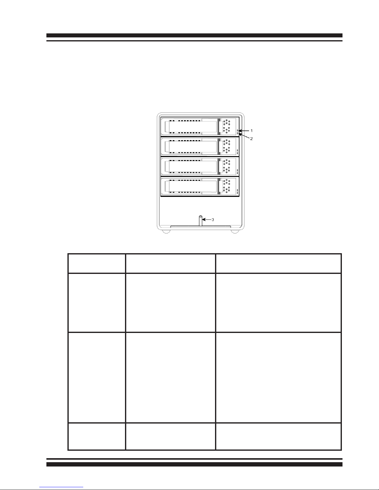
1.4.1 Drive Tray/Status LED Indicators
Figure 1-1, Drive Tray/Status LED
Drive Tray/
Status LED
Normal Status Problem Indication
1. Activity LED
(Blue)
1. When the activity LED
is lit, there is I/O
activity on that disk
drive.
2. When the LED is not
lit; there is no activity
on that disk drive.
N/A
2. Fault/
Link LED
(Red/Green)
1. When the fault LED is
lit, there is no disk
present.
2. When the link LED is
lit, there is a disk
present.
1. When the fault LED is off, the
disk is present and status is
normal.
2. When the fault LED is blinking
(2 times/sec.), the disk drive
has failed and should be hot swapped immediately.
3. When the activity LED is lit and
fault LED is fast blinking (10
times/sec.) there is rebuilding
activity on that disk drive.
3. Power/
Global Fault
(Green/Red)
Solid green, when the
power on.
Lit global fault LED indicates component failure or Urgent events
have occurred.

INSTALLATION
9
1.4.3 Thunderbolt Port LED Indicators
Figure 1-3, Thunderbolt Ports LED
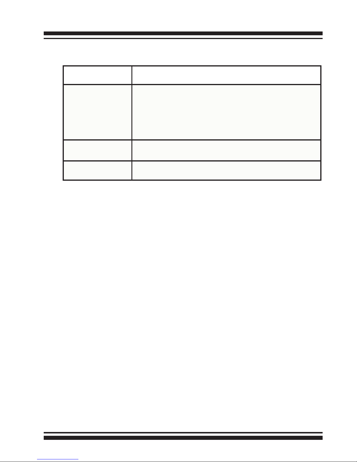
1.4.2 LCD Panel LED Indicators
There are a variety of status conditions that cause the RAID storage panel monitoring LED to light. The front panel LCD comes
with three (3) status-indicating LEDs. The LEDs on the front
panel are dened, from left to right, Power, Busy, and Caution, as
shown in Figure 1-2.
Figure 1-2, LCD Panel LED
The following table provides a summary of the front panel LED.
Panel LED Normal Status Problem Indication
1. Power LED
(Green)
Solid green, when power on. Unlit, when power on.
2. Busy LED
(Amber)
Blinking amber during host accesses RAID storage.
Unlit or never icker.
3. Caution LED
(Red)
Unlit indicates that the RAID
storage and all its components
are operating correctly.
Solid indicates that one or
more component failure/Urgent events have occurred.
INSTALLATION
10
The following table describes the ThunderBox 400 SATA RAID storage Thunderbolt port link LED behavior.
1.5 Setting Up RAID Storage
Setting up your ThunderBox 400 RAID involves these main steps:
• Physically Install the RAID Storage and Drives
• Install the MRAID Software
• Congure RAID Volumes
• Format RAID Volumes
• Unmounting RAID Volumes
Details about these steps are described in the following sections.
1.5.1 Physically Install RAID Storage and Drives
Please follow the steps below in order they are given to ensure
that your ThunderBox 400 connected on your Thunderbolt computer.
Step 1. Install the Drives in the ThunderBox 400 RAID
Your RAID storage supports up to 4 x 3.5-inch disk drives or 4 x
2.5-inch SATA 6.0Gb/s drives, each one contained in its individual
hole on the disk carrier. Each drive is hot-pluggable, allowing you
to remove and insert drives without shutting down your RAID
storage. Installation in this section describes how to install or
remove 3.5 inch drives in your RAID storage.
Thunderbolt
Ports Link LED
Status
Green light 1. Lit indicates RAID storage is powered and maintained
the daisy chain with other Thunderbolt devices.
2. Blinking (5 times/sec) that indicates RAID storage is
in sleep mode.
3. Blinking (1 time/sec) that indicates RAID storage is
powered down and maintained the daisy chain with
other Thunderbolt devices.
Amber light There is a proper DisplayPort connection on that Thunder-
bolt port.
Red light There is a proper DisplayPort to DVI connection on that
Thunderbolt port.
INSTALLATION
11
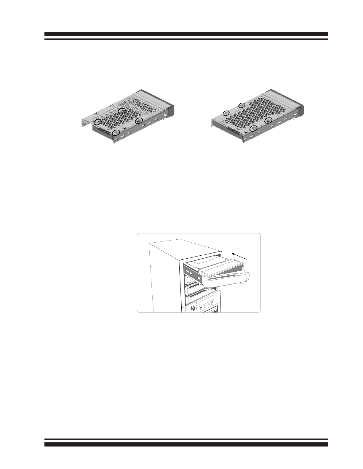
1. Gently slide the drive tray out from the ThunderBox 400 RAID .
2. Install the drive into the drive tray and secure the drive to the
drive tray by four of the mounting screws.
3. After all drives are in the drive tray, slide them back into
the ThunderBox 400 RAID storage and make sure you latch
the drive trays.
Figure 1-5, Sliding Drive Tray into Enclosure
Step 2. Connecting RAID Storage to Host Ports
Your ThunderBox 400 connects directly to your computer using the
following connectivity ports. Your ThunderBox 400 RAID features
two cutting-edge interfaces, Thunderbolt and SuperSpeed USB
(USB 3.0). We recommend that you use the fastest connection
available on your computer. You can use both interfaces connected
to the host, but you can only use one connection assigned by
ThunderBox 400 at a time. Interface that is connected 1st has
precedent.
Figure 1-4-1,
Installing 2.5-inch SATA Drive
Figure 1-4-2,
Installing 3.5-inch SATA Drive
INSTALLATION
12
THUNDERBOLT
Thunderbolt connectors are provided on the back of the
ThunderBox 400 RAID storage for connecting the array to
Thunderbolt host and next Thunderbolt devices. There are two
Thunderbolt connectors on the rear of ThunderBox 400 RAID
storage. You can plug-in two host ports.
1. Direct connection to a Thunderbolt capable computer.
2. Daisy chaining Thunderbolt capable devices and displays.
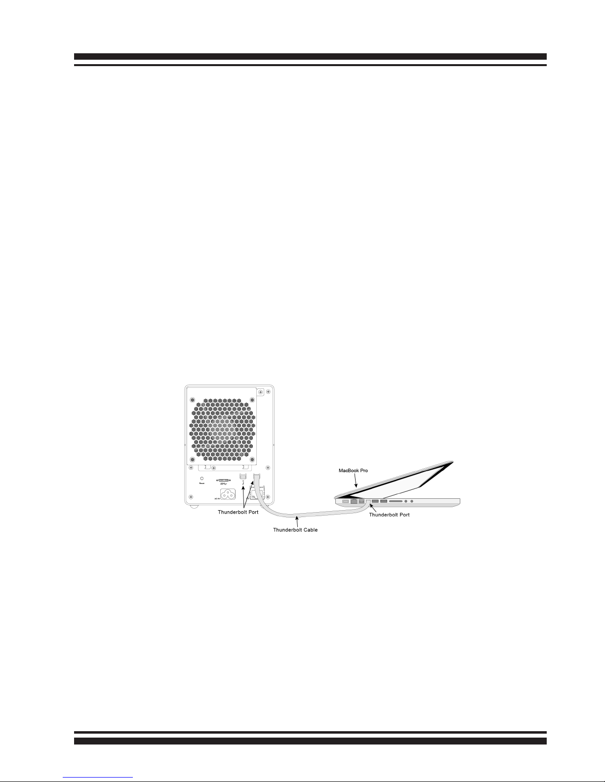
• Thunderbolt Computer Port Connection
By installing Thunderbolt technology capable computer and
ThunderBox 400 Thunderbolt port using the Thunderbolt
cable, which is included in your Thunderbolt capable computer.
Then connect ThunderBox 400 RAID storage and Thunderbolt
technology capable computer port as shown below:
Figure 1-6, Connecting to Thunderbolt Computer
• Daisy Chain Topologies
A single Thunderbolt technology daisy chain can have seven
devices, including the computer. Connect the cable to one of the
interface ports on the back of your ThunderBox 400 RAID and
to your Thunderbolt capable computer. The additional port may
be used to daisy chain compatible computer peripherals, such
as hard drives, monitors, and much more. A single Thunderbolt
port supports hubs as well as a daisy chain of up to seven Thun derbolt devices on, including the Thunderbolt computer.
 Loading...