

Thunderbolt ARC-8050 User Manual

ARC-8050
(Thunderbolt to 6Gb/s SAS RAID Storage)
User Manual
Version: 1.1
Issue Date: May, 2013
Thunderbolt™ Prod
uct

Copyright and Trademarks
The information of the products in this manual is subject to change
without prior notice and does not represent a commitment on the part
of the vendor, who assumes no liability or responsibility for any errors
that may appear in this manual. All brands and trademarks are the
properties of their respective owners. This manual contains materials
protected under International Copyright Conventions. All rights
reserved. No part of this manual may be reproduced in any form or by
any means, electronic or mechanical, including photocopying, without
the written permission of the manufacturer and the author.
FCC Statement
This equipment has been tested and found to comply with the limits for a Class B digital device, pursuant to part 15 of the FCC Rules.
These limits are designed to provide reasonable protection against interference in a residential installation. This equipment generates, uses,
and can radiate radio frequency energy and, if not installed and used
in accordance with the instructions, may cause harmful interference to
radio communications. However, there is no guarantee that interference will not occur in a particular installation.
Manufacturer’s Declaration for CE Certication
We conrm ARC-8050 has been tested and found comply with the requirements set up in the council directive on the approximation of the
low of member state relating to the EMC Directive2004/108/EC. For
the evaluation regarding to the electromagnetic compatibility, the following standards where applied:
EN 55022: 2006, Class B
EN 61000-3-2: 2006
EN 61000-3-3: 1995+A1: 2001+A2: 2005
EN 55024:1998+A1:2001=A2:2003
IEC61000-4-2: 2001
IEC61000-4-3: 2006
IEC61000-4-4: 2004
IEC61000-4-5: 2005
IEC61000-4-6: 2006
IEC61000-4-8: 2001
IEC61000-4-11: 2004

Contents
1. Introduction ................................................................ 8
1.1 Overview .........................................................................8
2. Installation ................................................................ 12
2.1 Before You First Installing................................................. 12
2.2 RAID Storage View .......................................................... 13
2.3 Locations of the Storage Component .................................. 14
2.3.1 Drive Tray LED Indicators ............................................ 14
2.3.2 LCD Panel LED Indicators ............................................ 15
2.3.3 Thunderbolt Port LED Indicators ................................... 15
2.4 Setting Up RAID Storage .................................................. 16
2.4.1 Software Installation ................................................... 16
2.4.2 Hardware Installation .................................................. 20
2.4.3 Volume Setup ............................................................ 24
2.4.3.1 Congure Volume Set ............................................ 25
2.4.3.2 Making Volume Sets Available to System .................. 26
2.4.4 Unmounting the Storage Volume .................................. 27
2.5 Summary of the Installation ............................................. 29
2.6 Hot-plug Drive Replacement ............................................. 31
2.6.1 Recognizing a Drive Failure ......................................... 31
2.6.2 Replacing a Failed Drive .............................................. 31
3. ArcHTTP Conguration .............................................. 32
• General Conguration: ................................................... 32
• Mail (alert by Mail) Conguration: ................................... 33
• SNMP Traps Conguration: ............................................. 34
• Rescan Device Conguration: .......................................... 36
• Collect Support Data: .................................................... 36
4. Web Browser-based Conguration ........................... 37
4.1 Start-up McRAID Storage Manager ................................... 37
• Start-up McRAID Storage Manager from Local Administration
(In-of-Band) .................................................................... 38
• Start-up McRAID Storage Manager Through LAN Port (Out-of-
Band) ............................................................................ 38
4.2 RAID storage McRAID Storage Manager ............................. 39
4.3 Main Menu .................................................................... 40
4.4 Quick Function ................................................................ 40
4.5 Raid Set Functions ..........................................................41
4.5.1 Create Raid Set ......................................................... 41

4.5.2 Delete Raid Set .......................................................... 42
4.5.3 Expand Raid Set ......................................................... 43
4.5.4 Ofine Raid Set .......................................................... 44
4.5.5 Rename Raid Set ........................................................ 44
4.5.6 Activate Incomplete Raid Set ....................................... 44
4.5.7 Create Hot Spare ....................................................... 45
4.5.8 Delete Hot Spare ........................................................ 46
4.5.9 Rescue Raid Set ......................................................... 46
4.6 Volume Set Functions ...................................................... 47
4.6.1 Create Volume Set (0/1/10/3/5/6) ............................... 47
• Volume Name ................................................................ 48
• Volume Raid Level ......................................................... 48
• Capacity ....................................................................... 48
• Greater Two TB Volume Support ....................................... 48
• Initialization Mode .......................................................... 49
• Stripe Size .................................................................... 49
• Cache Mode .................................................................. 49
• Tagged Command Queuing .............................................. 50
• SCSI Channel/SCSI ID/SCSI Lun ...................................... 51
4.6.2 Create Raid30/50/60 (Volume Set 30/50/60) ................. 51
4.6.3 Delete Volume Set ...................................................... 52
4.6.4 Modify Volume Set ...................................................... 52
4.6.4.1 Volume Growth ..................................................... 53
4.6.4.2 Volume Set Migration ............................................. 54
4.6.5 Check Volume Set ...................................................... 54
4.6.6 Schedule Volume Check .............................................. 55
6.6.8 Download Volume Key File ........................................... 56
4.7 Physical Drive ................................................................ 56
4.7.1 Create Pass-Through Disk ............................................ 56
4.7.2 Modify Pass-Through Disk ............................................ 57
4.7.3 Delete Pass-Through Disk ............................................ 57
6.7.4 Clone Disk ................................................................. 58
6.7.4.1 Clone And Replace ................................................. 59
6.7.4.2 Clone Only ........................................................... 59
6.7.5 Abort Cloning ............................................................. 59
4.7.6 Set Disk To Be Failed .................................................. 59
4.7.7 Activate Failed Disk .................................................... 60
4.7.8 Identify Enclosure ...................................................... 60
4.7.9 Identify Drive ............................................................ 60
4.8 System Controls .............................................................61
4.8.1 System Cong ........................................................... 61
• System Beeper Setting ................................................... 61

• Background Task Priority ................................................. 61
• JBOD/RAID Conguration ................................................ 62
• SATA NCQ Support ......................................................... 62
• HDD Read Ahead Cache .................................................. 62
• Volume Data Read Ahead ............................................... 62
• HDD Queue Depth ......................................................... 62
• Empty HDD Slot LED ...................................................... 63
• Max Command Length .................................................... 63
• Auto Activate Incomplete Raid ......................................... 63
• Disk Write Cache Mode ................................................... 63
• Write Same For Initialization ............................................ 63
• Hot Plugged Disk For Rebuilding ....................................... 63
• Disk Capacity Truncation Mode ......................................... 64
• Smart Option For HDD .................................................... 64
• Smart Polling Interval ..................................................... 65
4.8.2 Advanced Conguration ............................................... 65
• TLER Setting ................................................................. 65
• Timeout Setting ............................................................. 66
• Number of Retries .......................................................... 66
• Buffer Threshold ............................................................ 66
• Amount of Read Ahead ................................................... 66
• Number of AV Stream ..................................................... 67
• Optimize AV Recording .................................................... 67
• Read Performance Margin ................................................ 68
• Write Performance Margin ............................................... 68
• Read And Discard Parity Data .......................................... 68
4.8.3 HDD Power Management ............................................. 68
• Stagger Power On Control .............................................. 69
• Time to Hdd Low Power Idle ........................................... 69
• Time To Hdd Low RPM Mode ........................................... 69
• SATA Power Up In Standby ............................................. 70
4.8.4 Ethernet Conguration ............................................... 70
• DHCP Function ............................................................... 71
• Local IP address ............................................................. 71
• Gateway IP address ........................................................ 71
• Subnet Mask ................................................................. 71
• HTTP Port Number .......................................................... 71
• Telnet Port Number ........................................................ 72
• SMTP Port Number ......................................................... 72
4.8.5 Alert By Mail Conguration ......................................... 72
4.8.6 SNMP Conguration .................................................... 73
4.8.7 NTP Conguration ...................................................... 73

• NTP Sever Address ......................................................... 73
• Time Zone ..................................................................... 74
• Automatic Daylight Saving............................................... 74
4.8.8 View Events/Mute Beeper ............................................ 74
4.8.9 Generate Test Event ................................................... 74
4.8.10 Clear Events Buffer ................................................... 75
4.8.11 Modify Password ....................................................... 75
4.8.12 Update Firmware ..................................................... 76
4.9 Information .................................................................... 76
4.9.1 Raid Set Hierarchy ...................................................... 76
4.9.2 SAS Chip Information ................................................. 77
4.9.3 System Information .................................................... 77
4.9.4 Hardware Monitor ....................................................... 78
Appendix A ................................................................... 79
Upgrading Flash ROM Update Process ...................................... 79
Appendix B .................................................................... 82
Battery Backup Module (ARC-6120BAT021) .............................. 82
B-1 BBM Connector and Components .................................. 82
B-2 Status of BBM ............................................................ 82
B-3 Installation ................................................................ 83
Appendix C .................................................................... 86
SNMP Operation & Installation ................................................ 86
Appendix D .................................................................... 91
Event Notication Congurations .......................................... 91
A. Device Event ................................................................ 91
B. Volume Event ............................................................... 92
C. RAID Set Event ............................................................ 93
D. Hardware Monitor Event ................................................ 93
Appendix E .................................................................... 95
RAID Concept ...................................................................... 95
RAID Set ........................................................................... 95
Volume Set ........................................................................ 95
Ease of Use Features ........................................................... 96
• Foreground Availability/Background Initialization ................ 96
• Online Array Roaming ..................................................... 96
• Online Capacity Expansion ............................................... 96
• Online RAID Level and Stripe Size Migration ...................... 98
• Online Volume Expansion ................................................ 99
High Availability ................................................................. 99
• Global/Local Hot Spares .................................................. 99
• Hot-Swap Disk Drive Support ......................................... 100

• Auto Declare Hot-Spare ............................................... 100
• Auto Rebuilding ........................................................... 101
• Adjustable Rebuild Priority ............................................. 101
High Reliability ................................................................. 102
• Hard Drive Failure Prediction .......................................... 102
• Auto Reassign Sector .................................................... 102
• Consistency Check ....................................................... 103
Data Protection ................................................................ 103
• Battery Backup ........................................................... 103
• Recovery ROM ............................................................. 104
Appendix F .................................................................. 105
Understanding RAID .......................................................... 105
RAID 0 ............................................................................ 105
RAID 1 ............................................................................ 106
RAID 10(1E) .................................................................... 107
RAID 3 ............................................................................ 107
RAID 5 ............................................................................ 108
RAID 6 ............................................................................ 109
RAID x0 .......................................................................... 109
Single Disk (Pass-Through Disk) ......................................... 110
Summary of RAID Levels ................................................... 111

INTRODUCTION
8
1. Introduction
This section presents a brief overview of the 6Gb/s SAS RAID storage,
ARC-8050. (Thunderbolt to 6Gb/s SAS RAID storage)
1.1 Overview
Thunderbolt technology is a revolutionary high-speed, dual protocol I/O technology designed for performance, simplicity and exibility. Thunderbolt I/O technology lets you move data between
high-resolution displays and high-performance data devices on a
single, compact port. Both data and display signals can be sent
and received at the same time through dual 10Gbps channels. A
single cable attached to one of the ports provides 2 channels able
to achieve the 10Gbps speeds owing both ways simultaneously. A
single Thunderbolt port supports hubs as well as a daisy chain of
up to seven Thunderbolt devices. To improve bandwidth transmission, Thunderbolt has implemented two duplex (PCIe and DisplayPort) channels into the controller and each channel can provide full
bi-directional performance.
Unparalleled Performance
ARC-8050 is 8-bay 6Gb/s SAS Thunderbolt box with RAID control
capabilities solution for both PC and Mac. Thunderbolt host interface make ARC-8050 RAID box well suited for SOHO group professional who work at home and or in the ofce. Thunderbolt technology developed for high speed data transfer at the speed of 10Gbps
per channel. Thunderbolt port is shared by multiple devices and
can transfer data equally distribute to all connected devices. ARC8050 incorporated on-board high performance dual core 800Mhz
ROC storage processor and with 1GB DDR3-1333 SDRAM memory
on-board to deliver true high performance hardware RAID for the
demands of serious HD media creators needs. For example, the
benet for video editor by using ARC-8050 to unleash their professional creativity work in real-time, with the high-bandwidth allow
large amount of audio and video capture/mixing devices transferred faster with low latency and high-accurate synchronization
at 10Gbps. Data can be backed up and restored more quickly, so
there’s less waiting for achieved content to transfer or copy.

INTRODUCTION
9
Unsurpassed Data Availability
Designed and leveraged with Areca’s existing high performance
solution, the RAID storage delivers high-capacity at the best of cost
performance value. It supports the hardware RAID 6 engine to allow two HDDs failures without impact the existing data and performance. Its high data availability and protection derives from the
many advance RAID features. ARC-8050 Thunderbolt RAID storage
allows easy scalability from JBOD to RAID. It can be congured to
RAID levels 0, 1, 1E, 3, 5, 6, 10, 30, 50, 60, Single Disk for JBOD.
With innovative new ROC 6Gb/s SAS feature and support for SATA,
SAS and SSDs, the ARC-8050 provides powerful small-workgroup
server, power users and consumers with superior levels performance and enterprise level data protection for external storage.
The world today, large amounts of arrays data needs by the Professional content creation application for – video editing, capturing or
transferring video, managing 3D graphics design, producing video
presentations and regularly data backup. ARC-8050 Thunderbolt
RAID storage is the best solution.
Easy RAID Management
Conguration and monitoring can be managed either through the
LCD control panel, Archttp utility or Ethernet port. Firmware-embedded web browser-based RAID manager allows local or remote
to access it from any standard internet browser via a out-of-band
10/100Mbits LAN port or in-band Archttp utility. ARC-8050 Thunderbolt RAID storage also provides API library for customer to
combine with its own monitor utility. The intelligent cooling continuously adapts to environmental conditions by automatically
controlling the speed of the cooling fans. This super silent design,
optimizing balance between noise reduction and necessary cooling,
makes ARC-8050 well suited for audio/video application especially
the rapidly growing demand from the video editing markets.

INTRODUCTION
10
1.2 Features
Controller Architecture
• 800MHz Dual Core ROC processor
• 1GB on-board DDR3-1333 SDRAM with ECC protection
• Write-through or write-back cache support
• Support 8 internal 6Gb/s SAS ports
• Multi-RAID storage support for large storage requirements
• Support EFI BIOS for bootable from RAID storage volume
• NVRAM for RAID event & transaction log
• Redundant ash image for controller availability
• Battery Backup Module (BBM) ready (Option)
RAID Features
• RAID level 0, 1, 10(1E), 3, 5, 6, 30, 50, 60, Single Disk or JBOD
• Multiple RAID selection
• Online array roaming
• Ofine RAID set
• Online RAID level/stripe size migration
• Online capacity expansion and RAID level migration simultane-
ously
• Online volume set growth
• Instant availability and background initialization
• Support global and dedicated hot spare
• Automatic drive insertion/removal detection and rebuilding
• Greater than 2TB capacity per disk drive support
• Greater than 2TB per volume set (64-bit LBA support)
• Support intelligent power management to save energy and
extend service life
• Support NTP protocol synchronize RAID controller clock over the
onboard LAN port
Monitors/Notication
• System status indication through individual activity/fault LED,
LCD panel and alarm buzzer
• SMTP support for email notication
• SNMP support for remote manager
• Enclosure management ready
Drive Support
• Up to 8 x 6Gb/s SAS/SATA/SSD

INTRODUCTION
11
Host Connection
• Two Thunderbolt technology ports
• Simultaneous bi-directional, 10Gbps transfers over a single cable
• Dual-protocol support (PCI Express and DisplayPort)
• Compatible with existing DisplayPort devices
• Daisy-chaining devices
RAID Management
• Field-upgradeable rmware in ash ROM
In-Band Manager
• Firmware-embedded web browser-based McRAID storage man ager, SMTP manager, SNMP agent and Telnet function via ArcHttp
proxy server for all operating systems
• Support Command Line Interface (CLI)
• API library for customer to write monitor utility
Out-of-Band Manager
• Firmware-embedded web browser-based McRAID storage man ager, SMTP manager, SNMP agent and Telnet function via on board LAN port
• API library for customer to write monitor utility
• Support push button and LCD display panel
Operating System
• Mac OS X 10.6.x/10.7.x/10.8.x
• Windows 7/8
(For latest supported driver version visit http://www.areca.com.tw)
Mechanical Specications
• Form Factor: Compact – 8 Disk Compact Tower
• Operation temperature: 0° ~ 40°C
• Operation humidity: 5 ~ 95 %, Non-condensing
• Cooling Fan: 2 x 2700rpm/0.135A Brushless Fan
• Power Supply/In/out: 270W / 90-256V AC / +12V/26A,
+5V/18A, +3.3V/16A
• Dimension (W x H x D): 146 x 302 x 290 mm
(5.7 x11.8 x 11.4 in)
• Weight (Without Disk): 14.9 lbs / 6.8Kg

INSTALLATION
12
2. Installation
This section describes how to install the ARC-8050 Thunderbolt RAID
storage with host computer and disks.
2.1 Before You First Installing
Thanks for purchasing the ARC-8050 as your RAID data storage.
The following manual gives simple step-by-step instructions for
installing and conguring the ARC-8050 RAID storage.
Unpack
Unpack and install the hardware in a static-free environment.
ARC-8050 RAID storage is packed inside an anti-static bag between two sponge sheets. Remove it and inspect it for damage. If
the ARC-8050 RAID storage appears damaged, or if any items of
the contents listed below are missing or damaged, please contact
your dealer or distributor immediately.
Checklist
• 1 x ARC-8050 8-bays RAID storage unit
• 1 x Installation CD – containing driver, relative software, an
electronic version of this manual and other related manual
• 1 x RJ-45 LAN cable
• 1 x Power cord
• 32 x Drive mounting screws (4 per drive tray)
• 1 x Quick start guide
System Requirements
• Computer with Thunderbolt connector
• Mac OS X 10.6.8 or higher
• Windows 7&8
“For Windows PC: the Thunderbolt certied device driver must be
installed before plugging in the device for it to function properly”
• Thunderbolt cable
INSTALLATION
13
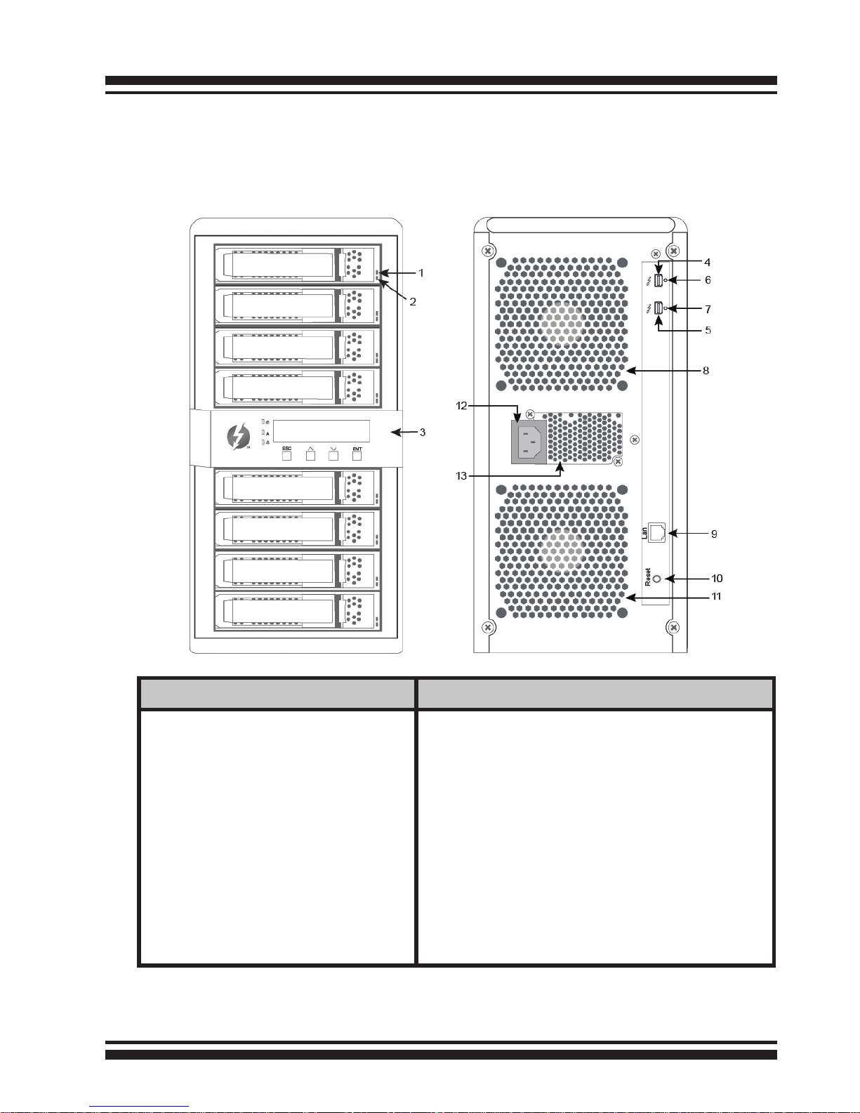
Front View
Rear View
1. Disk Activity LED
2. Disk Fault/Link LED
3. LCD Panel
with Keypad
4. Thunderbolt Port1
5. Thunderbolt Port2
6. Thunderbolt Port1 Link LED
7. Thunderbolt Port2 Link LED
8. System Fan1
9. LAN Port (For McRAID Web
Manager)
10. Reset Button
11. System Fan2
12. Power Connector
13. Power Supply Fan
2.2 RAID Storage View
The following diagram is the RAID storage front view and rear view.
INSTALLATION
14
2.3 Locations of the Storage Component
The following components come with LEDs that inform ARC-8050
RAID storage managers about the operational status.
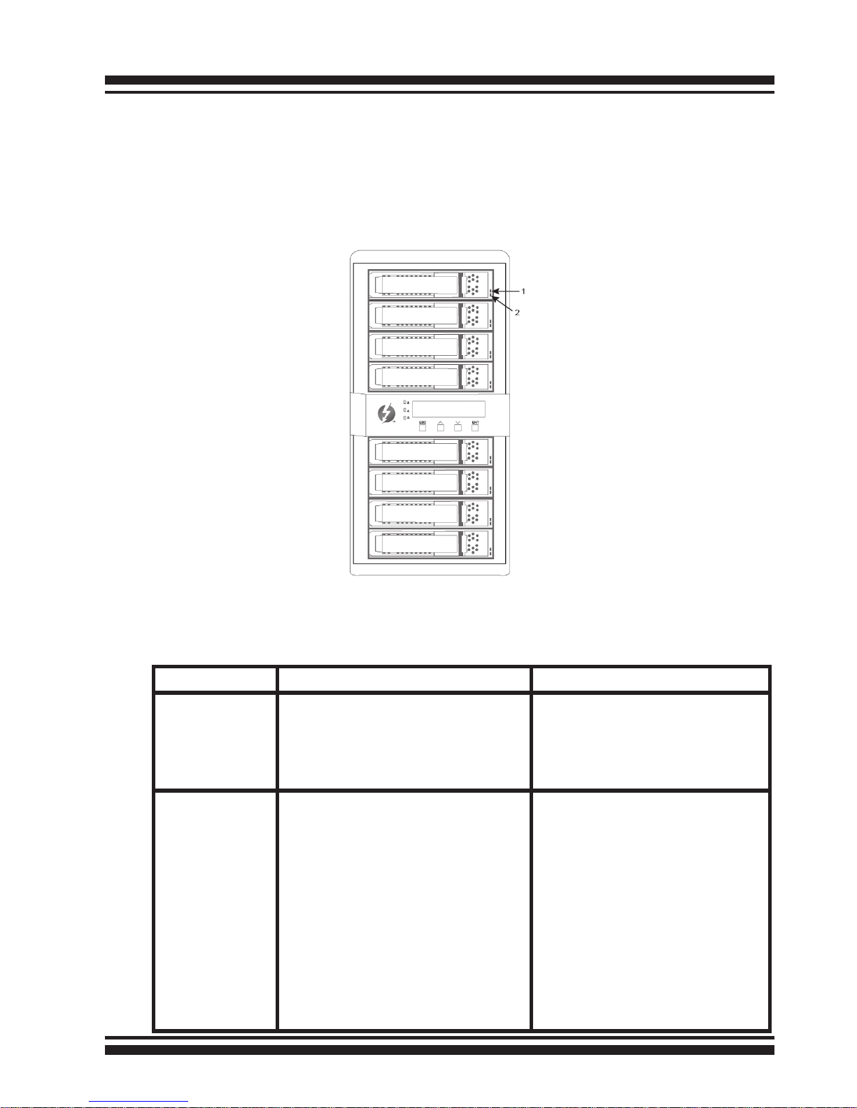
2.3.1 Drive Tray LED Indicators
Figure 2-1, Activity/Fault LED for ARC-8050 RAID Storage
The following table describes the RAID storage disk drive tray LED
behavior.
Tray LED Normal Status Problem Indication
1. Activity
LED (Blue)
When the activity LED is illuminated, there is I/O activity
on that disk drive. When the
LED is dark; there is no activity
on that disk drive.
N/A
2. Fault/Link
LED (Red/
Green)
When the fault LED is solid
illuminated, there is no disk
present.
When the link LED is solid
illuminated, there is a disk
present.
When the fault LED is off,
that disk is present and status is normal.
When the fault LED is slow
blinking (2 times/sec.), that
disk drive has failed and
should be hot-swapped immediately. When the activity LED is illuminated and
fault LED is fast blinking (10
times/sec.) there is rebuilding activity on that disk
drive.
INSTALLATION
15
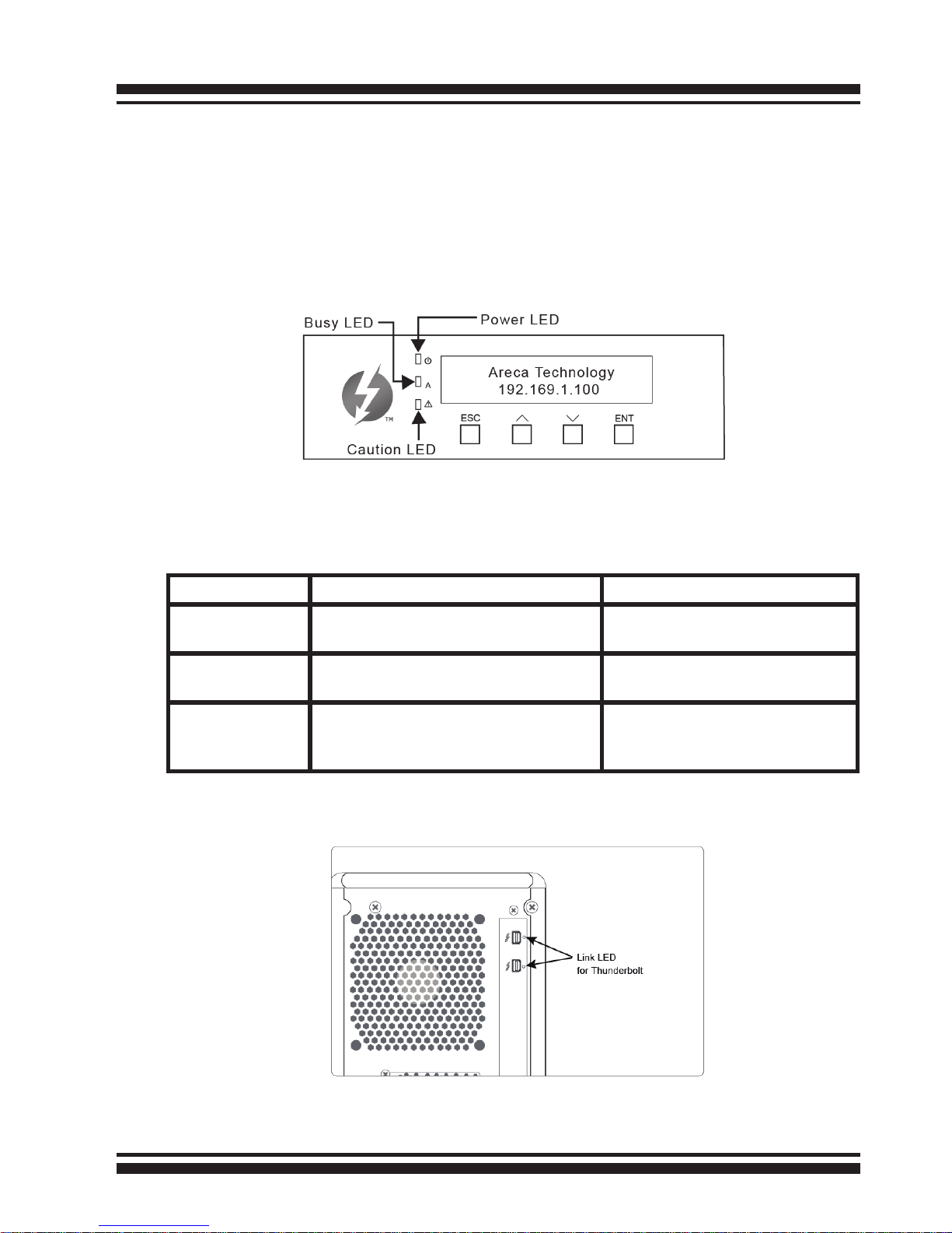
2.3.2 LCD Panel LED Indicators
There are a variety of status conditions that cause the RAID storage panel monitoring LED to light. The front panel LCD comes
with three (3) status-indicating LEDs. The LEDs on the front panel
are dened, from top to bottom, Power, Busy, and Caution, as
shown in Figure 2-2.
Figure 2-2, LCD Panel LED for ARC-8050 RAID Storage
The following table provides a summary of the front panel LED.
Panel LED Normal Status Problem Indication
1. Power LED
(Green)
Solid green, when power on Unlit, when power on
2. Busy LED
(Amber)
Blinking amber during host accesses RAID storage
Unlit or never icker
3. Caution LED
(Red)
Unlit indicates that the RAID
storage and all its components
are operating correctly.
Solid indicates that one or
more component failure/Urgent events have occurred.
2.3.3 Thunderbolt Port LED Indicators
Figure 2-3, Thunderbolt ports LED for ARC-8050 RAID storage
INSTALLATION
16
The following table describes the ARC-8050 SAS RAID storage
Thunderbolt port link LED behavior.
2.4 Setting Up RAID Storage
Follow the instructions below to install ARC-8050 Thunderbolt to
6Gb/s SAS RAID storage.
2.4.1 Software Installation
To install the ARC-8050 driver and software into the existing
operating system. Driver is required for the operating system to
be able to interact with the ARC-8050 RAID storage. Windows
users must rstly install drivers on their computer in order to use
the Thunderbolt connection. You can click the “For Windows,
Install Driver First” on the http://www.areca.com.tw/
proucts/thunderbolt.htm web link to driver and set up instruc-
tions for Windows.
ArcHTTP has to be installed for GUI RAID console (McRAID storage manager) to run. ArcHttp proxy server is used to launch the
web-browser McRAID storage manager. McRAID storage manager
provides all of the creation, management and monitor ARC-8050
RAID storage status.
This chapter describes how to install the ARC-8050 RAID storage software to your operating system. The software installation
includes device driver, ArcHTTP and CLI.
Thunderbolt Ports
Link LED
Status
Link LED
(Green light)
1. Solid illuminated that indicates RAID storage powered up and maintained the daisy chain with other
Thunderbolt devices.
2. Fast blinking (5 times/sec) that indicates RAID storage in sleep mode.
3. Slow blinking (1 times/sec) that indicates RAID
storage powered down and maintained the daisy chain
with other Thunderbolt devices.
Link LED
(Amber light)
There is a proper DisplayPort connection on that Thunderbolt port.
Link LED
(Red light)
There is a proper DisplayPort to DVI connection on that
Thunderbolt port.
INSTALLATION
17
For PC Thunderbolt compatible system:
In this scenario, you are installing the RAID storage in an existing
Windows system. This section describes detailed instructions for
installing the Windows driver & utility for the ARC-8050. You can
use the installer to install driver & Archttp at once or “Custom” to
install special components.
To follow the following process to install driver & utility on
Windows as below:
1. Insert the ARC-8050 software CD in the CD-ROM drive or
download installer from http://www.areca.com.tw/support/s_
thunderbolt/thunderbolt.htm and unzip the le.
2. Run the setup.exe le that resides at: <CD-ROM>\PACKAGES\
Windows on CD-ROM or from the website to launch the installer.
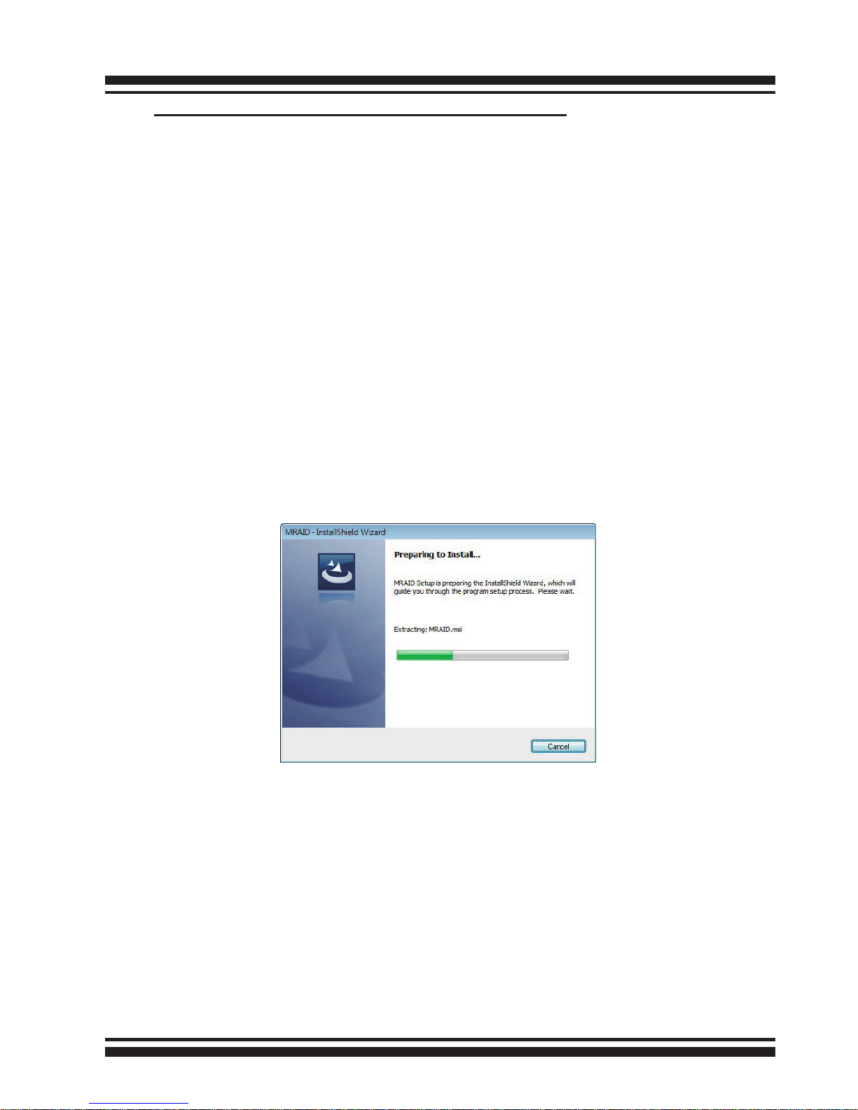
3. The screen shows “Preparing to Install”.
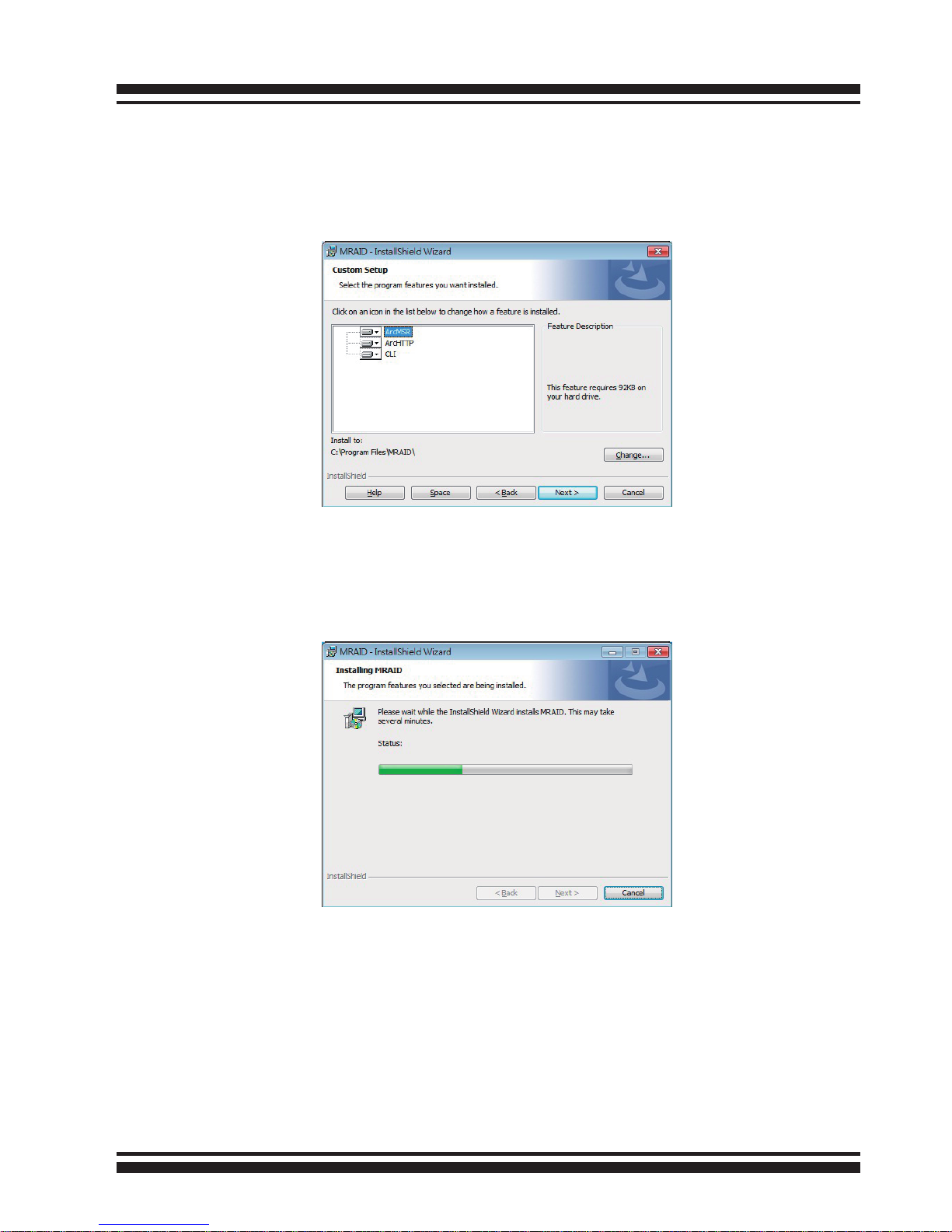
4. Follow the installer on-screen steps, responding as needed, to
complete the driver, ArcHTTP and CLI utility installation.
• Driver is required for the operating system to be able to inter act with the Areca RAID controller.
• ArcHTTP has to be installed for GUI RAID console (MRAID
storage manager) to run. It also runs as a service or daemon
in the background that allows capturing of events for mail and
SNMP traps notication. Refer to the chapter 3 Archttp Conguration on ARC-8050 user manual, for details about the mail and
SNMP traps conguration.
INSTALLATION
18
• CLI (Command Line Interface) lets you set up and manage
RAID controller through a command line interface. Arc-cli per
forms many tasks at the command line. You can download arc-cli
manual from Areca website or software CD <CDROM>\ DOCS
directory.
5. When you reach the installation page, click the “Install” button.
A program bar appears that measures the progress of the driver
installation. When this screen completes, you have completed the
driver installation.
6. Normally ArcHTTP and CLI are installed at the same time on
ARC-8050. Once ArcHTTP and CLI have been installed, the archttp
background task automatically starts each time when you start
your computer. There is one MRAID icon showing on your “Pro
grams” folder. This icon is for you to start up the McRAID storage
manager (by ArcHTTP) and CLI utility.
INSTALLATION
19
Note:
“For Windows, Install Driver First”
For Windows PC: the Thunderbolt certied device driver
must be installed before plugging in the device for it to
function properly.
For Mac Thunderbolt capable system:
This section describes detailed instructions for installing the Areca
Mac driver & utility for the ARC-8050 on your Apple Thunderbolt
capable machine. You must have administrative level permissions
to install Areca Mac driver & utility. You can use the installer to
install Areca Mac driver & utility (MRAID) at once or “Custom”
to install special components. To follow the following process to
install driver & utility on Apple Mac Pro as below:
1. Insert the Areca Mac Driver & Software CD that came with your
ARC-8050 storage unit.
2. Double-click on the “install_mraid.zip” le that resides at <CDROM>\packages\MacOS to add the installer on the Finder.
3. Launch the installer by double-clicking the install_mraid on the
Finder.
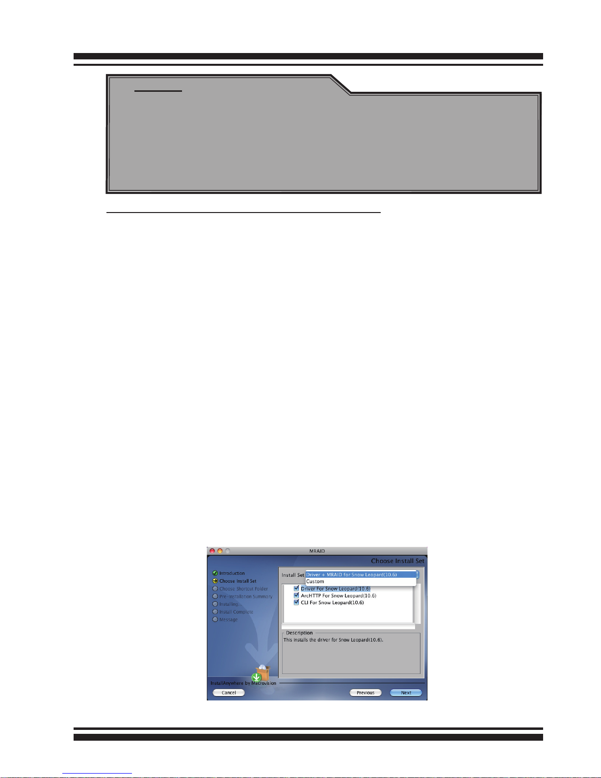
4. Follow the installer on-screen steps, responding as needed, to
complete the Areca driver and MRAID (ArcHTTP and CLI utility)
installation.

INSTALLATION
20
• Driver is required for the operating system to be able to inter act with the Areca RAID controller.
• ArcHTTP has to be installed for GUI RAID console (MRAID
storage manager) to run. It also runs as a service or daemon
in the background that allows capturing of events for mail and
SNMP traps notication. Refer to the Chapter 5 Archttp Conguration on ARC-8050 user manual, for details about the mail and
SNMP traps conguration.
• CLI (Command Line Interface) lets you set up and manage
RAID controller through a command line interface. Arc-cli per
forms many tasks at the command line. You can download arc-cli
manual from Areca website or software CD <CDROM>\ DOCS
directory.
5. When you reach the installation page, click the “Install”
button. A program bar appears that measures the progress of the
driver installation. When this screen completes, you have completed the driver installation.
6. A reboot is required to complete the installation (This will start
the ArcHTTP so RAID Console can be used).
7. Normally archttp64 and arc_cli are installed at the same time
on ARC-8050. Once archttp and arc_cli have been installed, the
archttp background task automatically starts each time when you
start your computer. There is one MRAID icon showing on your
desktop. This icon is for you to start up the McRAID storage
manager (by archttp) and arc_cli utility.
2.4.2 Hardware Installation
Please follow the steps below in order they are given to sesure
that your ARC-8050 conndected on your Thunderbolt computer.
Step 1. Install the Drives in the ARC-8050 RAID Storage
1. Gently slide the drive tray out from the ARC-8050 RAID
storage.

INSTALLATION
21
Figure 2-4, Secure the drive to the drive tray
2. Install the drive into the drive tray and secure the drive to
the drive tray by four of the mounting screws.
Figure 2-5, Slide drive tray back into the ARC-8050 RAID storage
3. After all drives are in the drive tray, slide all of them back
into the ARC-8050 RAID storage and make sure you
latch the drive trays.
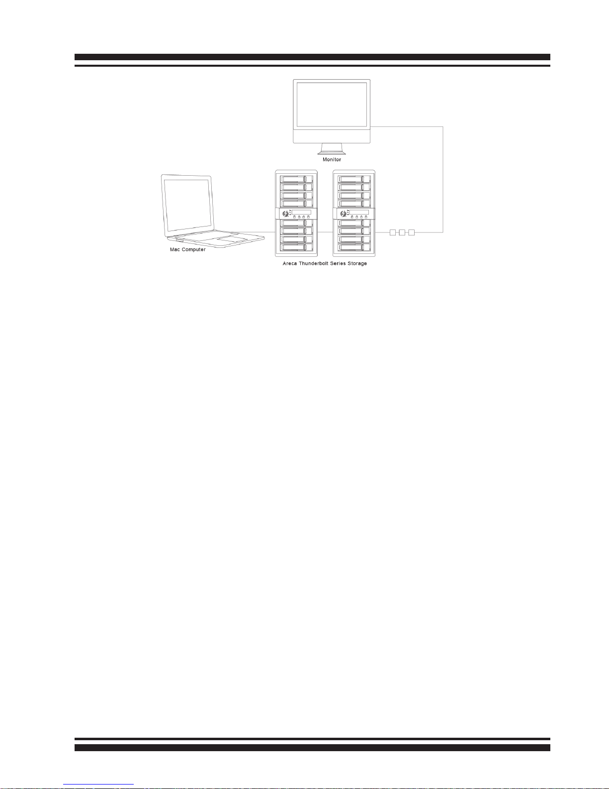
Step 2. Connecting RAID Storage to Thunderbolt Ports
Thunderbolt connectors are provided on the back of the ARC-8050
RAID storage for connecting the array to Thunderbolt host and
next Thunderbolt devices. There are two Thunderbolt connectors
on the rear of ARC-8050 RAID storage. You can plug-in two host
ports.
1. Direct connection to a Thunderbolt technology capable
computer.
2. Daisy chaining Thunderbolt capable devices and displays.
• Thunderbolt Computer Port Connection
By installing Thunderbolt technology capable computer and ARC8050 Thunderbolt port using the Thunderbolt cable which is
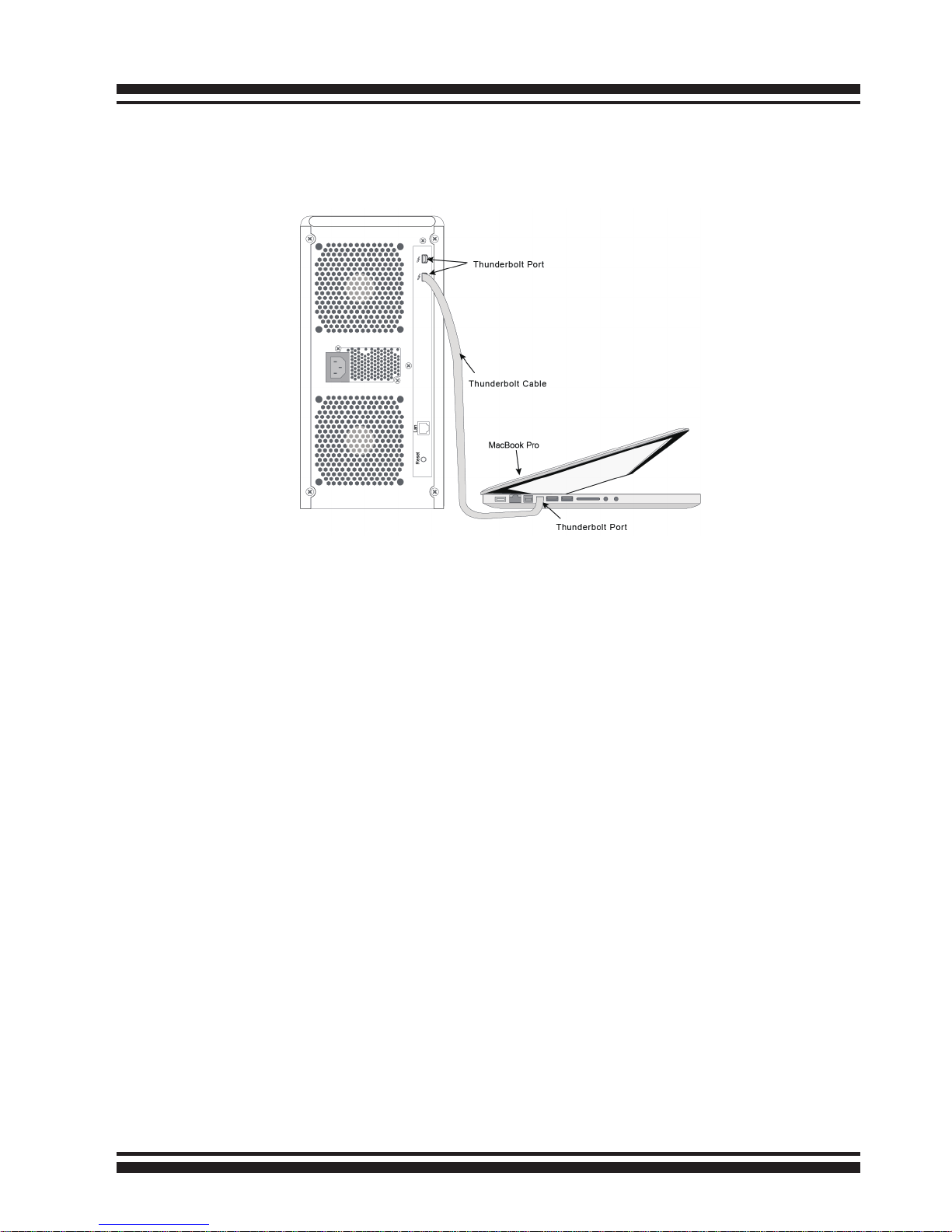
INSTALLATION
22
included in your Thunderbolt capable computer. Then connect
ARC-8050 RAID storage and Thunderbolt technology capable
computer port as shown below:
• Daisy Chain Topologies
A single Thunderbolt technology daisy chain can have seven
devices, including the computer. Connect the cable to one of the
interface ports on the back of your ARC-8050 RAID storage and
to your Thunderbolt capable computer. The additional port may
be used to daisy chain compatible computer peripherals, such as
hard drives, monitors, and much more. A single Thunderbolt port
supports hubs as well as a daisy chain of up to seven Thunderbolt
devices on, including the Thunderbolt capable computer.
Figure 2-6, Connect ARC-8050 RAID storage and Thunderbolt
computer
INSTALLATION
23
Figure 2-7, Thunderbolt computer daisy chain
Step 3. Connecting Monitor Port
ARC-8050 RAID storage is normally delivered with LCD preinstalled. You can connect LAN port to the manager clinet system,
if you want to congure and manage the RAID storage from the
clinet system through out-of-band manager.
• LAN Port Connection
ARC-8050 RAID storage has embedded the TCP/IP & web
browser-based RAID manager in the rmware (method 1). User
can remote manage the RAID enclosure without adding any
user specic software (platform independent) via standard web
browsers directly connected to the 10/100Mbit RJ45 LAN port.
Connect LAN port of the ARC-8050 using the included Ethernet
cable and then to a LAN port or LAN switch.
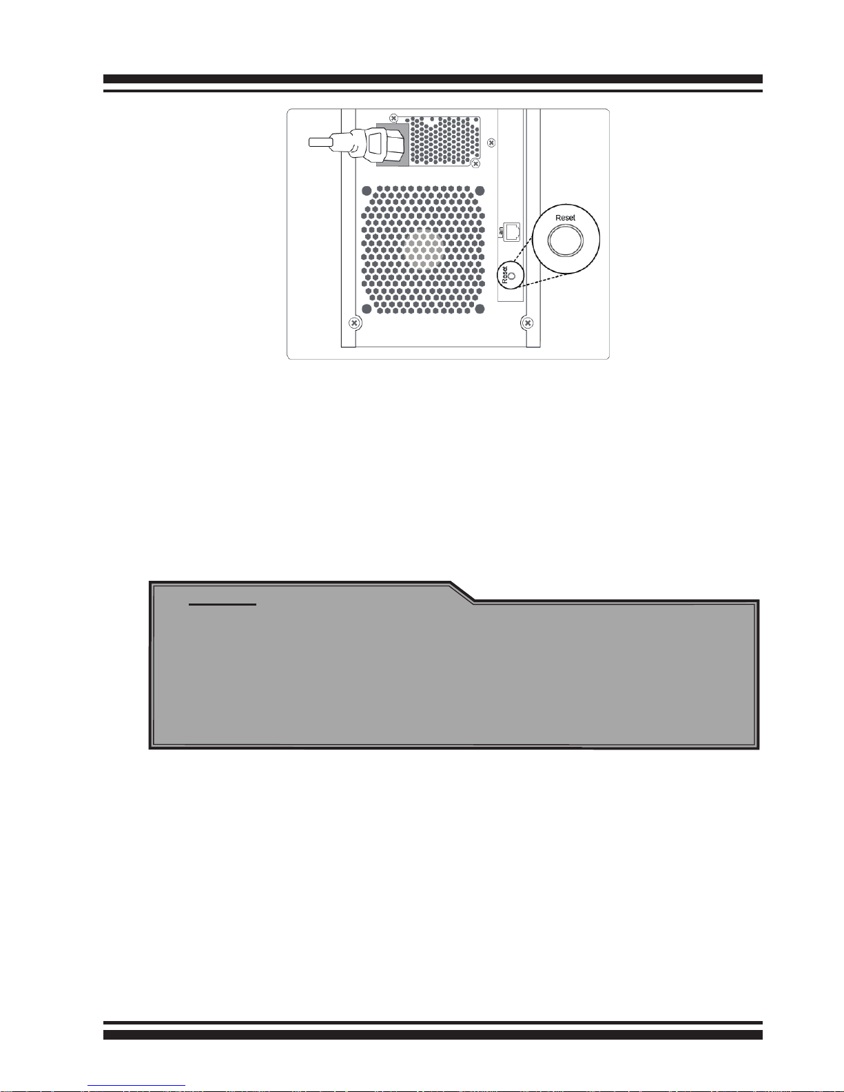
Step 4. Connecting RAID Storage Power
To power the RAID storage:
1. Using the included power cord, connect this power cord to a
grounded electronical outlet and to the ARC-8050 RAID storage.
2. ARC-8050 RAID storage will turn on automatically when host
computer with the power on is received by the ARC-8050. It takes
about 30 seconds to fully start up the RAID storage.
INSTALLATION
24
3. ARC-8050 RAID storage automatically turns off when host
computer power off is detected by the ARC-8050.
When you are nished installing the ARC-8050 RAID storage, you
can set up the RAID volume using McRAID storage manager or
LCD to set up RAID volumes.
2.4.3 Volume Setup
After hardware installation, the SAS/SATA disk drives connected
to the ARC-8050 must be congured and the volume set units
initialized by the controller before they are ready to use by
the system. With MRAID software installed on your host computer
and cables connected, you are ready to turn on your ARC-8050
storage unit and use the McRAID Storage Manager to setup RAID
volumes.
Note:
1. User can press and hold the “Reset” button 3 seconds to
turn on/off the RAID storage AC power.
2. RAID storage will maintain the daisy chain with other
Thunderbolt devices even when the RAID storages have
been powered down.
Figure 2-8, Connect the power cord to a grounded electrical outlet
and to the ARC-8050 RAID storage.
INSTALLATION
25
2.4.3.1 Congure Volume Set
ARC-8050 RAID storage is normally delivered with LCD pre-installed. Your ARC-8050 RAID storage can be congured by using
McRAID storage manager (launched by ArcHttp proxy server and
LAN port) or LCD with keypad (refer to ARC-8050_LCD manual).
Thunderbolt RAID storage default User Name is “admin” and the
Password is “0000”.
• Method 1: Thunderbolt Connection (McRAID Storage Manager)
ARC-8050 RAID storage has embedded the TCP/IP & web browser-based RAID manager in the rmware. User can remote manage the RAID storage using Archttp proxy server installed via
standard web browsers.
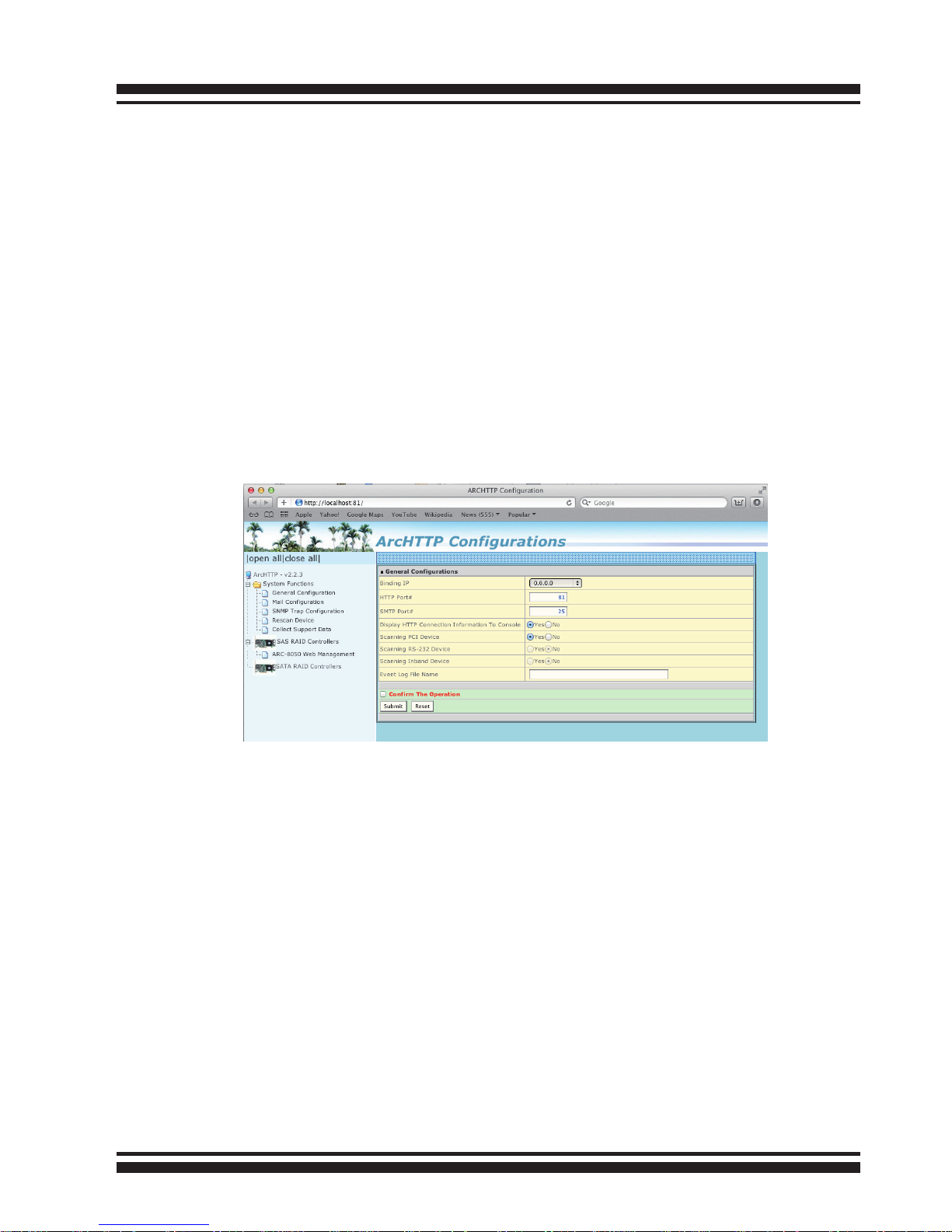
Start McRAID Storage Manager – Browser Edition
(1) In Windows, right-click on “Start” menu and choose “Programs”. Clicking “MRAID” program icon starts the Archttp utility
(From the Start menu, choose Programs > MRAID > ArcHTTP).
(2) On a Mac, there is one MARID icon showing on your desktop. This icon is for you to start up the McRAID storage manager
(by ArcHTTP) and CLI utility.
When you click the archttp, it shows all RAID storages available
on the system and create an individual RAID storage icon located on left column of the “Archttp Congurations” screen. This
RAID storage icon is for user to launch the selected RAID storage web browser McRAID RAID Storage Manager.
INSTALLATION
26
If there is any RAID storage missed on the system start-up or
plug-in on-lne, you can use the “Rescan Device” function. See
chapter 4 on ARC-8050 user manual for information on customizing your RAID volumes using McRAID storage manager.
Thunderbolt RAID storage default User Name is “admin” and the
Password is “0000”.
• Method 2: LAN Port Connection (McRAID Storage Manager)
ARC-8050 RAID storage has embedded the TCP/IP & web
browser-based RAID manager in the rmware. User can remote
manage the RAID storage directly connected to the 10/100Mbits
RJ45 LAN port via standard web browsers. For additional information on using the McRAID storage manager to congure the
RAID storage see the Chapter 4 “Web Browser-Based Conguration” on ARC-8050 user manual.
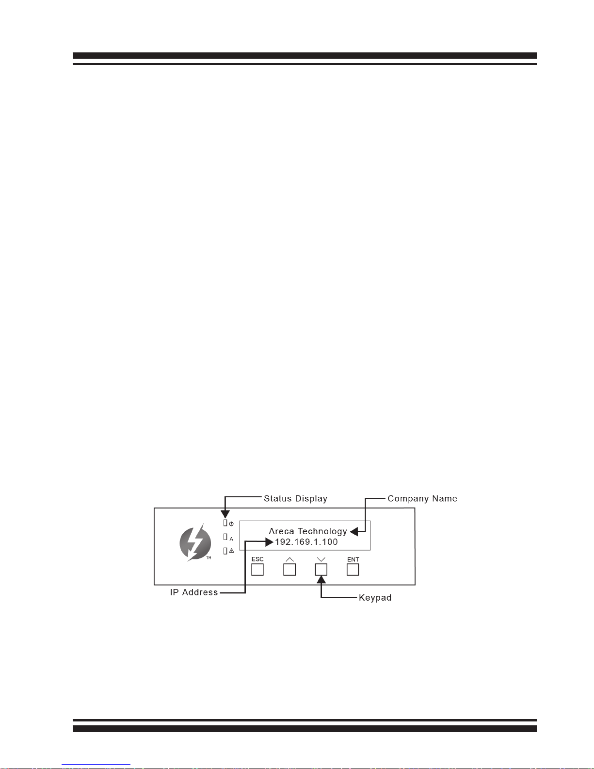
• Method 3: LCD Panel with Keypad
You can use LCD front panel and keypad function to simply create the RAID volume. The LCD status panel also informs you of
the disk array’s current operating status at a glance. For additional information on using the LCD to congure the RAID storage see the ARC-8050_LCD manual on the shipping CD. The LCD
provides a system of screens with areas for information, status
indication, or menus. The LCD screen displays up to two lines at
a time of menu items or other information.
The LCD initial screen is shown as the following:
2.4.3.2 Making Volume Sets Available to System
After the volume set is ready for system accesses, it needs to be
partitioned, formatted, and mounted by the operating system.
There are various steps, depending on what operating system
you are using. Detailed steps for each operating system are
provided on their disk utility.

INSTALLATION
27
For PC Thunderbolt compatible system:
The following steps show how to make any new disk arrays or
independent disks accessible to Windows system. This procedure
assumes that the ARC-8050 RAID storage hardware, driver, and
Windows are installed and operational in your system.
1. Partition and format the new arrays or disks using “Disk Administrator”:
a. Choose “Administrative Tools” from the “Start” menu.
b. Choose “Computer Management” from the “Administrative
Tools” menu.
c. Select “Storage”.
d. Select “Disk Management”.
2. Follow the on-screen prompts to write a signature to the
drive.
3. Right click on the drive and select “Create Volume” from the
menu.
4. Follow the on-screen prompts to create a volume set and to
assign a disk drive letter.
For Mac Thunderbolt capable system:
When you create a volume through McRAID storage manager,
the Mac OS X recognizes that a new disk is avail, and displays a
message asking what you next want to do. If the message does
not show up, start the “Macintosh Disk Utility” manually from
the “Finder”, use the “Go” menu and open the “Utilities” folder.
Double-click on the “Macintosh Disk Utility” program. Follow the
on-screen prompts to create a volume set and to assign a disk
drive letter.
2.4.4 Unmounting the Storage Volume
For PC Thunderbolt compatible system:
Thunderbolt technology devices are plug and play, allowing you to
connect and disconnect them while the host computer is running.
In some cases, disconnect the volume without properly
INSTALLATION
28
Note:
You can also safely remove devices from the computer
folder. Click the "Start" button, click "Computer", right-click
the device you want to remove, and then click "Eject".
unmounting the volume results in data corruption. To prevent the
potential data corruption problems, it is important to properly
Safely Remove the Thunderbolt storage volume(s).
This will show you how to use "Safely Remove Hardware and
Eject Media" in Windows to safely shutdown and eject a storage
device before just unplugging or disconnecting it to help prevent
accidental data loss if data were still being copied or saved to
or from the device. Windows provides a way to help you safely
remove such devices.
If you see the "Safely Remove Hardware and Eject Media" icon in
the notication area, at the far right of the taskbar, you can use
this as an indication that your devices have nished all operations
in progress and are ready to be removed. If you don't see the
"Safely Remove Hardware and Eject Media" icon, click the Show
hidden icons button to display all icons in the notication area.
The notication area, at the far right of the taskbar to safely
remove a certain device, click the "Safely Remove Hardware
and Eject Media" icon, and then, in the list of devices, click the
Thunderbolt storage volume that you want to remove. Windows
will display a notication telling you it's safe to remove the
Thunderbolt storage volume. Now you can unplug the Thunderbolt
cable or press and hold "Reset" button 3 seconds to save energy.
The RAID storage will maintain the daisy chain with other Thunderbolt devices even when the RAID storages have been powered
down.
For Mac Thunderbolt capable system:
To avoid possible data corruption, Areca recommends that ARC8050 RAID storages volume(s) be properly unmounted from the
Mac OS X prior to turning off the RAID storage or safely removing
the Thunderbolt interface cable.
INSTALLATION
29
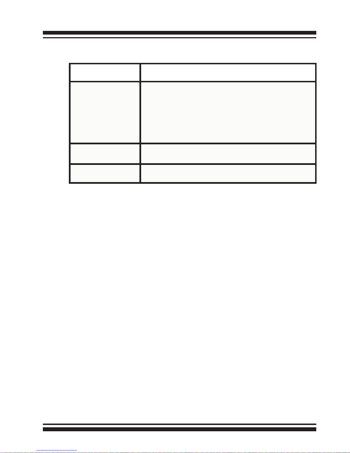
Conguration Utility Operating System Supported
McRAID Storage Manager
(Via Ethernet port)
OS-Independent
McRAID Storage Manager
(Via Archttp proxy server)
Mac OS X 10.6.x/10.7.x/10.8.x
Windows 7/8
Thunderbolt technology devices are plug and play, allowing
you to connect and disconnect them while the host computer is
running. In some cases, disconnect the volume without properly
unmounting the volume results in data corruption. To prevent the
potential data corruption problems, it is important to properly
eject the Thunderbolt storage volume(s).
1. Drag RAID storage volume(s) icon to the trash. The Trash will
turn into an Eject arrow. This will assure that all data is properly
cleared from the system memory before the volume is removed.
2. When the volume icon disappears from the desktop, RAID
storage can be disconnected from the computer or you can press
and hold "Reset" button 3 seconds to save energy. The RAID storage will maintain the daisy chain with other Thunderbolt devices
even when the RAID storages have been powered down.
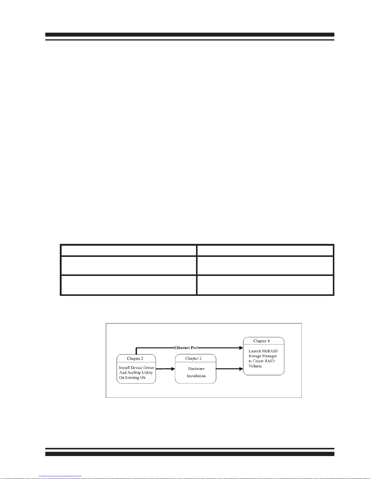
2.5 Summary of the Installation
The software components congure and monitor the ARC-8050
RAID storage as following table.
The ow chart below describes the installation procedures for ARC8050 Thunderbolt RAID storage.
These procedures include hardware installation, the creation and
conguration of a RAID volume through the McRAID manager, OS
installation and installation of storage software.

INSTALLATION
30
McRAID Storage Manager
Before launching the rmware-embedded web server, McRAID
storage manager through the Thunderbolt port, you rst need to
install the ArcHttp proxy server on your server system. The RAID
storage can also be congured through the McRAID storage manager through on-board LAN port. If you need additional information
about installation and start-up of this function, see Chapter 4 “Web
Browser-Based Conguration” on ARC-8050 user manual.
SNMP Manager Console Integration
There are two ways to transport SNMP data on the ARC-8050 RAID
storage: Out-of-Band built-in LAN interface or In-Band Thunderbolt
interface. Enter the “SNMP Tarp IP Address“ option on the rmware-embedded SNMP conguration function for user to select the
SNMP data agent-side communication from the Out-of-Band built-in
LAN interface. To use In-Band Thunderbolt interface, keep blank on
the “SNMP Tarp IP Address“ option.
• Out of Band-Using Onboard LAN Port Interface
Out-of-band interface refers to transport SNMP data of ARC-8050
RAID storage from a remote station connected to the controller
through a network cable. Before launching the SNMP manager
on clinet, you rst need to enable the rmware-embedded SNMP
agent function and no additional agent software inquired on
your server system. If you need additional information about
installation and start-up this function, see the section 4.8.4
"SNMP Conguration" on ARC-8050 user manual.
• In Band-Using Thunderbolt Port Interface
In-band interface refers to management of the SNMP data of
ARC-8050 RAID storage from a Thunderbolt port. In-band interface is simpler than out-of-band interface for it requiresless hardware in its conguration. To enable the RAID storage
to send the SNMP traps to client SNMP manager using the IP
address assigned to the operating system, such as Net-SNMP
manager, you can simply use the SNMP function on the ArcHttp
proxy server utility. The Archttp proxy server only provides
one direction to send the trap to the SNMP manager without
needing to install the SNMP extension agent on the host. If SNMP
manager requests to query the SNMP information from RAID
 Loading...