

Page 1
Owners manual
SPACE PR350 B V350
Manufactured under license from Dolby Laboratories. ”Dolby”, ”ProLogic II” and the double-D symbol are trademarks of Dolby Laboratories.
Confidential unpublished works. © 1992-1997 Dolby Laboratories Inc. All rights reserved.
Manufactured under license from Digital Theater Systems, Inc. US Pat. No. 5,451,942, 5,956,674, 5,974,380, 5,978,762 and other world-wide
patents issued and pending. "DTS", "DTS-ES Extended Surround" and "Neo:6" are trademarks of Digital Theater Systems, Inc. Copyright
1996, 2000 Digital Theater Systems, Inc. All Rights Reserved.
Thule Audio ApS has the right to make changes without prior notice
Page 2

Page 3

INDEX
OVERVIEW OF REMOTE CONTROL......................................................................................................... 4
OVERVIEW OF REAR AND FRONT PANEL ............................................................................................. 5
OVERVIEW OF CONTROL PANEL AND DISPLAY................................................................................. 6
CONGRATULATIONS WITH YOUR NEW PREAMPLIFIER/PROCESSOR SPACE PR350 B. ......... 7
0. INSTALLATION........................................................................................................................................... 9
1. INPUT SELECTION ..................................................................................................................................... 9
2. VOLUME CONTROLS .............................................................................................................................. 10
3. ZONE 2 ......................................................................................................................................................... 11
4. DELAY ......................................................................................................................................................... 11
5. SURROUND MODES ................................................................................................................................. 13
5.1 D
OLBY DIGITAL
5.2 DTS ......................................................................................................................................................... 14
5.3 D
OLBY PROLOGIC
5.4 PCM
5.5 S
6. CONFIG MENU .......................................................................................................................................... 16
6.1 S
6.2 I
6.3 N
6.4 C
6.5 E
6.6 D
6.7 V
6.8 S
6.9 R
6.10 OSD....................................................................................................................................................... 20
6.11 SPDIF OUT........................................................................................................................................... 20
6.12 P
6.13 PROL
6.14 V
6.15 V
AND ANALOGUE INPUTS
IDE CHANNELS
PEAKERS
NPUTS
..................................................................................................................................................... 18
OISE
....................................................................................................................................................... 18
ROSSOVER FREQUENCY
XTENDED SURROUND
YNAMIC RANGE COMPRESSION
OLUME SCALE
AVING SET-UP PARAMETERS IN MEMORY
ETURN TO FACTORY SETTING
OWER AMP CONTROL
OGIC
IDEO INPU T OUTPUT
IDEO MISCELLANEOUS
....................................................................................................................................... 13
II ................................................................................................................................ 15
.................................................................................................................. 15
....................................................................................................................................... 16
................................................................................................................................................ 17
.......................................................................................................................... 18
............................................................................................................................. 18
............................................................................................................... 18
........................................................................................................................................ 19
................................................................................................ 19
................................................................................................................. 20
........................................................................................................................... 20
II .......................................................................................................................................... 20
............................................................................................................................. 21
.......................................................................................................................... 21
TECHNICAL SPECIFICATIONS................................................................................................................. 22
7.0 YOUR NOTES ........................................................................................................................................... 23
APPENDIX A: SPECIAL FUNCTIONS ....................................................................................................... 24
A.1 C
OMMUNICATION BETWEEN
O
VERVIEW: COMMUNICATION BETWEEN
A.2 A/D
A.3 E
A.4 A
LEVEL
............................................................................................................................................. 26
LECTRICAL (COAXIAL) VERSUS OPTICAL DIGITAL INPUT
UTOMATIC FAILURE CORRECTION SYSTEM
PR350 B
PR350 B
AND
IA/PA350 B/PA250 B ........................................................ 24
AND
PA350 B.................................................................. 25
......................................................................... 26
............................................................................................ 26
___________________________________________________________________________
page 3
Page 4
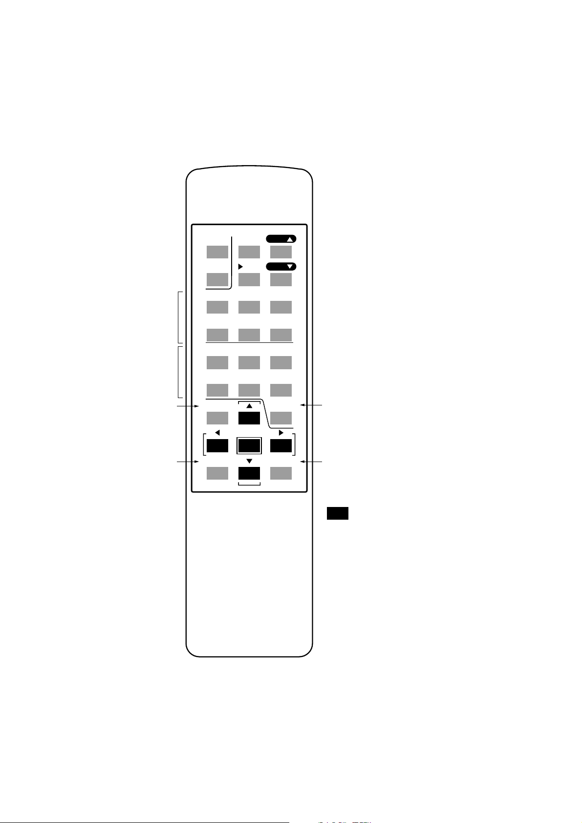
REMOTE CONTROL
channel balance
double push: delay
input selection
received input status
change surround mode
STBY
[STATUS]
[MODE]
MUTE
DIM
L
SL SUB SR
DVD
TAPE 1
LD TAPE 2
ENTER
VOL
C
SAT
VOL
VOL
PURE A.
[CONFIG]
TV
standby | mute -20dB | increase volume
change light | return to master volume | decrease volume
R
left | center | right
surround left | subwoofer | surround right
DVD player | sattelite receiver | TV-set
laser disc | audio/video tape1 | audio/video tape2
pure audio input
enter config mode
navigate in config menu
Page 5
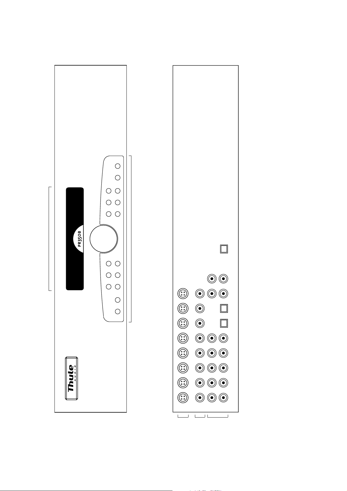
display: see next page
FRONT PANEL AND REAR PANEL
volume control | control panel: see next page
S-video inputs
inputs
composite video
to DSP
analog audio inputs
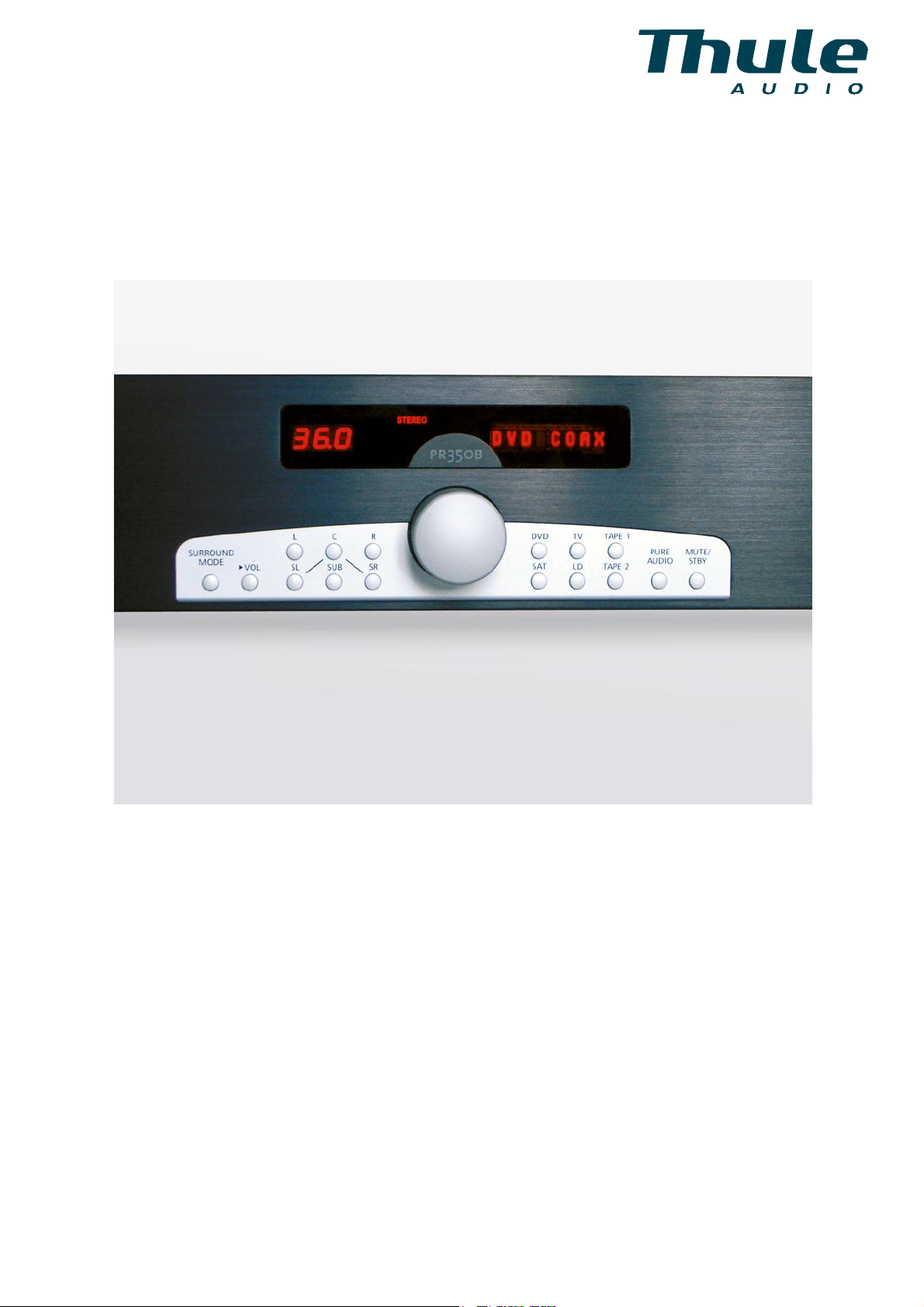
Page 6
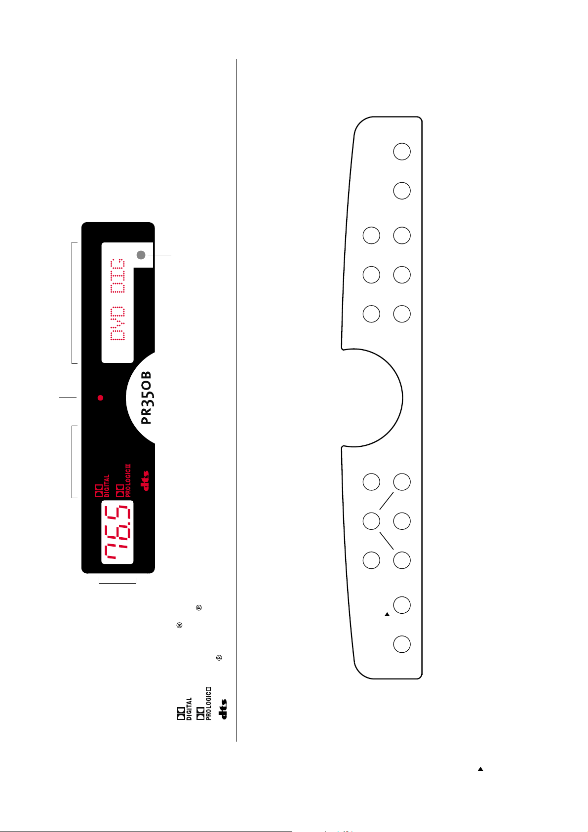
pure audio input
short push: mute -20dB
2 sec push: standby
multi functional display
standby indicator
surround mode
ZONE 2
STEREO
remote sensor
2 channel stereo
Adjustments Zone 2
DISPLAY
DVD player
DVD
TV-set
audio/video tape1
TV
TAPE 1
TAPE 1
TV
DVD
R
PURE MUTE/
AUDIO STBY
TAPE 2
LD
SAT
SR
PURE
AUDIO
sattelite receiver
laser disc player or
LD
SAT
STBY
MUTE/
audio/video tape2
CD player
TAPE 2
CONTROL PANEL
volume level
100: max
0: min
ZONE 2
STEREO
Dolby Digital surround
Dolby ProLogic II surround
DTS digital surround
left channel balance
/ left
L
short push: center channel balance
2 sec. push: center channel delay
/up
C
right channel balance
/ right
R
C
L
SURROUND
SUB
SL
VOL
MODE
short push: surround left channel balance
2 sec. push: surround left channel delay
/ enter
SL
short push: change surround mode
2 sec. push: input format information
MODE
SURROUND
short push: subwoofer balance
2 sec push: LFE balance
/ down
SUB
short push: back to master volume
2 sec. push: enter config mode
/ exit config menu
VOL
short push: surround right channel balance
2 sec. push: surround right channel delay
SR
main function
/ function in config mode
Page 7

Congratulations with your new Preamplifier/Processor SPACE PR350 B.
The SPACE PR350 B contains advanced technology for an outstanding range of
features and sound performance.
We are sure that the PR350 B will give you long lasting pleasure.
To give you full benefit from this advanced product, please read this manual carefully
before you proceed.
The SPACE PR350 B contains following features:
- Pure analogue input with 6 channels and true balanced signal path in the L and
R channels
- 32 – 96 kHz PCM stereo
- 96kHz Dolby ProLogic II decoding
- Dolby Digital decoding with auto detection
- DTS 5.1, DTS 6.1 discrete, DTS 6.1 matrix and DTS 24bit/96kHz decoding with
auto detection
- Extended precision decoder improves dynamic range for 24bit DTS up to
117dBA
- New 56367 Motorola DSP with 160 MIPS (Million Instructions Per Second)
- Upgradable design for coming sound formats
- 10 pcs. Burr Brown 24bit/192kHz D/A converters
- True differential D/A conversion in all channels,
- Direct key access to channel trim adjustments with 0.5dB adjustment step
Precision volume control for all 10 channels with 0.5dB adjustment step and
100dB range
- Delay adjustment for center, surround left, surround right and surround center
channels
- Common delay (Lip sync) for all channels up to 5ms.
- Direct key access to input selection
- Most inputs can be assigned as analogue, electrical digital or optical digital
- Sensitivity for analogue inputs to DSP is adjusted automatically for improved
dynamic range
- Test Noise signal in all channels including subwoofer, to set up volume trim.
- Component, S-video and composite video switching with 4-line adaptive comb
filter, so that only one RGB or Component video connection to TV / Projector is
necessary.
- Progressive video pass-through with 100MHz bandwidth
- Video encoder with On Screen Display (OSD), which is automatically bypassed
when not used
- Flexible speaker settings with extensive bass management
- Adjustable crossover frequency (60 – 120Hz) for bass management
- Dynamic range compression for both DTS and Dolby Digital, e.g. for improved
performance in noisy environments
Each feature is described further in the next pages.
___________________________________________________________________________
page 7
Page 8

Following formats are used:
Cursive text indicates display readout, e.g.: CONFIG
Key type is indicated with “”, e.g.: “ENTER” key.
Stereo speakers:
“L” : left speaker
“R” : right speaker
Surround speakers:
“C” : center speaker placed in front of the listening position
“SL” : surround left speaker placed rear left of the listening position
“SR” : surround right speaker placed rear right of the listening position
Extended surround speakers:
“SC” : surround center speaker placed back of the listening position.
“SSL” : reserved for future upgrade. Output L channel.
“SSR” : reserved for future upgrade. Output R channel.
___________________________________________________________________________
page 8
Page 9

0. Installation
Place the amplifier on a hard and flat surface. The ventilation holes should not be
covered. There has to be at least 5 cm (2 inches) free air on top of the amplifier.
To ensure long and trouble free operation we recommend:
- Do not expose the amplifier to direct sunlight.
- Do not place the amplifier in warm or dusty environments.
Caution: Because of risk of fire or electric shock, do not expose the amplifier to rain or
moisture.
Caution: Because of risk of electric shock, do not open the amplifier.
1. Input selection
The input selection is very flexible, so it can suit many different home theatre and
stereo installations. It is possible to switch between seven different inputs, which are
directly accessed by keys on the front panel or on the remote control.
Each input can be configured in different ways, shown below with an “X”.
The factory settings are marked with [ ] brackets. Changes to this setting can be
made under the config.input menu.
INPUTS
Analogue
Coax digital [X]
Dig. Direct X
Optical
Com.video
S-video
Component [X]
DVD
X
X
SAT
X
[X]
LD
X
[X]
TV
[X]
X
Tape 1 Tape 2 Pure A.
[X]
[X]
[X]*
[X]
X
X
X
[X]
[X]
X
X
[X]
X
[X]
*The Pure Audio input can be either XLR stereo or 6 channel RCA phono input
.
For the audio signals, one of four options in the upper three rows must be selected
under the config.input menu.
Similarly, the video inputs configuration must be selected for PR350B in the
config.video-input-output menu. After video switching, the built-in adaptive comb
filter converts the selected video source into component or RGB video format.
Therefore, your projector or TV must be set correctly to either RGB or component,
and the “intelligent” video switching in your PR350B will take care of the rest.
The Pure Audio input can be selected as both XLR balanced or unbalanced phono
input. A short push on the “PURE AUDIO” key selects the XLR input. By holding
down this button down for more than one second or double push on the remote
control, you select the Pure Audio phono input. The Pure Audio input will bypass the
DSP circuits and is recommended for high quality music listening in stereo e.g. from
CD player or other analogue source.
Alternatively, for high quality music listening in stereo, connect the digital output from
___________________________________________________________________________
page 9
Page 10

a CD player or DVD player to one of the available digital inputs in the PR350 B and
use the balanced 24bit D/A conversion for L and R channels, built into the PR350 B.
The Space PR350 B is also optimised for D/A conversion of the 24bit/96kHz stereo
DVD disc’s with music.
2. Volume controls
The master volume level is set by rotating the volume knob on the front panel or by
using the “VOL ⇑” or VOL ⇓” key on the remote control.
The volume adjustments are scaled, so that at normal listening levels, the setting is
very accurate with 0.5dB steps, while at lower levels the step size increases to allow
a more rapid setting. This scaled volume setting may be the most convenient for
normal users, and is set as default.
However, it is possible to change the volume to 0.5dB steps for the entire volume
range by changing it in the config.volume menu.
The volume trims between each channel are set under the config.noise menu by
comparing the perceived sound volume from each channel via the built-in noise
generator, so that you can compensate for speaker sensitivity differences and
distances from listening position.
We recommend that the settings for each channel obtained under the config.noise
option are used as initial settings for each of the memory banks: Stereo, ProLogic II,
Dolby Digital and DTS. See further descriptions about the mem banks in section 5.
However, each surround mode may lead to a different setting of volume trims based
on individual requirements. At Thule Audio’s experience in Dolby Digital and
ProLogic II mode, the gain can be increased 3 – 6 dB in the surround speakers than
“measured” under the noise test, to obtain a more realistic surround image. And also
in DTS mode the gain can be increased with 2 – 4 dB in the surround speakers.
These more practical settings based on individual requirements can then be stored
under each memory bank for automatic reload depending on actual surround mode.
Each movie or music source may also lead to a different setting of volume trims.
Therefore it is possible to adjust the volume trim “on the fly” directly by pushing the
channel “L”, “C”, “R”, “SL”, “SUB” or “SR” key on the front panel or remote control.
Subsequently the extended surround channels “SC”,”SSL” and “SSR” can be
selected for adjusting by using the arrow keys. The channel level can then be
adjusted by rotating the volume knob on the front panel or by pressing the “VOL ⇑”
or VOL ⇓” key on the remote control.
The volume trim settings changed “on the fly” will return to the default settings stored
in the memory banks, when the PR350 B is set into standby or powered off.
By pushing the “SUB” key on the front panel in for 2 seconds the LFE (low frequency
effect) channel is selected for adjusting. The LFE channel is the bass information,
which is sent to the subwoofer or alternatively sent to the “L” and “R” channels, if the
subwoofer is deactivated. In this way it is possible to adjust the low frequency
content even when no subwoofer is present.
The normal display returns 15 sec. after the last action on any of the channel select
keys or by pushing the ”>VOL” key.
___________________________________________________________________________
page 10
Page 11

3. Zone 2
With zone 2 it is possible to redirect the sound to other audio systems, e.g. placed
in kitchen or bedrooms. The zone 2 has separate volume control and input selector.
Adjustments for zone 2 are achieved by holding down the same input knob as
currently selected. E.g. when DVD input is selected, hold down the “DVD” knob on
remote or frontpanel, approx. 1 sec.
Then the ZONE2 indicator becomes active.
Possible inputs are: SAT ANLG
TV ANLG
LD ANLG
TAPE1 ANLG
Z1 -> Z2 (Input selected in the main zone is played in zone 2)
Even if an input is defined as digital in the main zone, the analog option is chosen in
zone 2.
The operation returns to the main zone 15 sec. after the last adjustment in zone 2 or
by pushing the ”>VOL” key.
4. Delay
To experience the best surround sound quality, it is important that the sound signal
from all the speakers arrives at the same time at the listening position. If the
listening position is placed closer to the rear surround speakers, the sound from
these speakers will arrive earlier at the listening position. In this case, it is necessary
to delay the sound slightly from the rear speakers.
The important issue here is the difference in distance from the listening position to
the front and rear speakers.
The same problem arises for the center speaker, if it is placed closer to the listening
position than the front speakers.
On some video sources, the video is delayed compared to the audio, due to video
processing. To compensate for video delay it is possible to delay all audio channels
up to 5ms. This common delay is called “Lip sync”.
The delays are set directly from the front panel keys by pushing the “SL”, “SR” or “C”
keys for more than two seconds or double push on the same knobs on the remote
control.
The display corresponds shortly with the message DELAY and afterwards the delay
setting for the selected channel is displayed, e.g. SL 5.0ms. Subsequently the
delay of the extended surround channel SC and “Lip Sync” can be selected by using
the arrow keys.
The delay can then be changed in steps of 1.0ms by turning the volume knob or
pressing the “VOL ⇑” or “VOL ⇓” key on the remote control.
The normal display returns after 15 seconds from last change or by pushing the
“>VOL” key. The setting is expressed in milliseconds, but the delay can be
calculated from the physical distance.
___________________________________________________________________________
page 11
Page 12

A sound wave travels at approx. 340 meter/sec., which is equivalent to:
1 foot in 1 millisecond or
1 meter in 3 milliseconds
Following example demonstrate how to calculate the delay setting for SL, SR, SC
and C:
From the listening position to each speaker, we measure following distances:
Example Your measurements
Listening position <-> Left speaker: 3.8 m (= 11.4 ft)
Listening position <-> Right speaker: 3.8 m (= 11.4 ft)
Listening position <-> Center speaker: 2.9 m (= 8.7 ft)
Listening position <-> Left surround speaker: 2.1 m (= 6.3 ft)
Listening position <-> Right surr. speaker: 2.1 m (= 6.3 ft)
Listening position <-> Center surr. speaker: 1.8 m (= 6.3 ft)
The delays when measuring the distance in meters are then calculated as:
SL delay : (L - SL distance) x 3 = (3.8 - 2.1) x 3 = 5.1ms
SR delay : (R - SR distance) x 3 = (3.8 - 2.1) x 3 = 5.1ms
C delay : (L - C distance) x 3 = (3.8 - 2.9) x 3 = 2.7ms
SC delay : (L - C distance) x 3 = (3.8 - 1.8) x 3 = 6ms
or when the distance is measured in feet:
SL delay : L - SL distance = 11.4 - 6.3 = 5.1ms
SR delay : R - SR distance = 11.4 - 6.3 = 5.1ms
C delay : L - C distance = 11.4 - 8.7 = 2.7ms
SC delay : L - SC distance = 11.4 - 5.4 = 6ms
In this example, we would set the delay to:
SL 5.0ms C 3.0ms SR 5.0ms SC 6.0ms
The above calculations for delay are based on the physical installation and should
be stored as the initial settings in the memory banks (see section 5).
However, at Thule Audio’s experience the delay could be further increased about 0
– 3 milliseconds in the surround speakers from the above calculations, to obtain a
more realistic surround sound image.
For each surround mode the preferred settings should be stored in the memory
banks for automatic reload.
___________________________________________________________________________
page 12
Page 13

The user may still prefer to change delays during playback of a movie, based on
subjective preference in a specific movie.
Hence the delay can also be set “on the fly”.
The intermediate delay settings will return to the default settings stored in the
memory banks when the PR350 B is set into standby or powered off.
5. Surround Modes
The actual surround mode of the PR350 B is always indicated in the display:
Possible input types:
- Stereo analogue input, PCM or Dolby Digital 2.0 bitstream
- Dolby ProLogic II analogue input, PCM or Dolby Digital 2.0 bitstream
- Dolby Digital Dolby Digital 5.1 bitstream.
- DTS DTS bitstream: 5.1, ES 6.1 discrete or 96kHz 5.1
5.1 Dolby Digital
If a Dolby Digital 5.1 surround bitstream is detected, the PR350 B will automatically
switch to Dolby Digital surround and the Dolby Digital indicator will light up.
By pushing the “SURROUND MODE” key on the front panel or “mode” on the
remote control, information about which outputs can be expected to be active, are
indicated, thus:
L: left speaker
R: right speaker
C: center speaker
SC: surround center speaker
SL: surround left speaker
SR: surround right speaker
SW: subwoofer
The number of active outputs will depend on which speakers are activated in the
config.speaker and config.extended surround menu, received input type (analogue,
PCM, Dolby Digital bitstream or DTS bitstream) and eventually the selected
surround mode.
By pushing the “SURROUND MODE” key for more than one second, information
about the received bitstream will be displayed:
Active audio channels in the received bitstream:
2/0 : L, R are present
2/1 : L, R, S are present*
2/2 : L, R, SL, SR are present*
3/0 : L, R, C are present*
3/1 : L, R, C, S are present*
3/2 : L, R, SL, SR, C are present*
*If not all speakers are selected under the config.speaker menu, down mixing will occur.
___________________________________________________________________________
page 13
Page 14

And the transmission bit rate of the received bitstream:
32k : 32 kbit/sec.
.
.
448k : 448 kbit/sec.
768k : 768 kbit/sec. (only DTS)
1411k : 1411 kbit/sec. (only DTS)
1532k : 1532 kbit/sec. (only DTS)
If only two audio channels are active in the received Dolby Digital bitstream (2/0),
the input is assumed to be Dolby ProLogic II, if indicated in the bitstream, otherwise
as two channel stereo.
In case of only two audio channels are active, the user can toggle between STEREO
and Dolby ProLogic II by an additional short push on the “SURROUND MODE” key.
In this case both the Dolby Digital and Stereo or the Dolby Digital and Dolby
ProLogic II indicators are turned on. See further information about ProLogic II below.
The normal display returns after 15 sec. from last push on “SURROUND MODE” or
by pushing the ”>VOL” key.
5.2 DTS
Generally DTS offer the same information and possibilities as described above for
Dolby Digital. But DTS also contains additional possibilities as described in the
following.
Several new DTS formats are supported:
DTS 24bit:
The DTS encoding resolution is indicated at DTS lock on, second line. E.g. 768k/24
means a 768kHz transmission bitrate with a 24bit encoding resolution.
PR350 B offer extended precision decoding of DTS 24bit stream to take full
advantage of this increased resolution. This improves dynamic range for DTS 24bit
of up to 117dBA, which is fully comparable with DVD Audio. But DTS 24bit stream
can be played on normal DVD Video players. Several mainstream DVD Video disc’s
are already encoded with DTS 24bit, e.g.: “Pearl Harbour”, “Jurassic Park III”,
”Gladiator”, “Bowfinger” and “The Haunting”.
DTS ES 6.1 Discrete and DTS ES 6.1 Matrix:
Some DTS disc’s are encoded with a discrete center surround channel, called “6.1
Discrete”. If such DVD disc’s are played, PR350B will indicate ES 3/3.1 at lock on.
This means three front channels (L, C, R) and three surround channels (SL, SC,
SR) are present in the DTS stream. If “6.1 Discrete” is enabled under the
config.extended surround menu, the PR350B will automatically activate the
extended surround channel, SC.
Examples of DTS ES 6.1 Discrete DVD disc’s are “Gladiator” and “The Haunting”.
A few other DVD disc are encoded with DTS ES 6.1 Matrix, where the extended
surround channel, SC is generated by a matrix process on the surround channels,
SL and SR.
An example of DTS ES 6.1 Matrix disc is “Terminator II, special edition”.
___________________________________________________________________________
page 14
Page 15

DTS 6.1 Compatible:
This DTS mode is actually identical to DTS ES 6.1 Matrix as described above, but
by enabling this mode the user choose always to activate the matrix process on the
SL and SR to generate the SC channel. DTS 6.1 Compatible will work on Dolby
Digital 5.1 streams, too. Try out e.g. the “Black Hawk Down” disc.
If the installation contains three surround channels, 6.1 Compatible will improve the
surround experience on nearly all 5.1 encoded music and movie CD/DVD disc’s.
Also 6.1 Compatible will generate the same sound information in the SC channel as
the THX Surround EX process.
In this case the user should enable both “6.1 Discrete + Matrix” and “6.1
Compatible” under the config.extended surround menu.
DTS 96kHz:
DTS offer a new format, also supported by PR350 B, where D/A conversion takes
place at 96kHz. The encoding resolution is also 24bit, thus the format is normally
referred to as “DTS 24/96”. PR350 B will automatically detect this type of bitstream
and display 96k 5.1. No interaction from the user is necessary.
The 6.1 Compatible mode is automatically disabled and no sound comes from the
SC channel in 96kHz mode.
The “Queen: A night at the opera” CD in DTS 24/96 demonstrates the usefulness of
this format.
The DTS 24/96 format is compatible in performance with DVD Audio, but can be
played on normal CD or DVD video players.
5.3 Dolby ProLogic II
The PR350 B support the new format ProLogic II, which generate surround and
center channels from a normal stereo signal. Compared with the conventional
ProLogic, the new ProLogic II among other things offers, separate SL and SR
channels with full bandwidth information.
PR350 B supports separate music and movie mode for ProLogic II. The normal
movie mode concentrate to much information in the center channel for music,
therefore the special music mode spread out the music in the center channel to the
L & R speakers.
Thule Audio finds the music mode very useful especially for some live recordings,
but it is also a matter of taste, if it is used.
For each input the user can decide by default , if Music or Movie mode, or no
ProLogic II is activated, under the config.ProLogic II menu
The surround mode can be toggled between STEREO and Dolby ProLogic II by an
additional short push on the “SURROUND MODE” key.
As a unique feature in PR350 B, ProLogic II is supported for 96kHz sample rate.
This is useful as the high quality A/D converter in PR350 B operates at 96kHz and
also some DVD’s operate at 96kHz.
5.4 PCM and analogue inputs
An analogue input is present if the letters “ANLG” is indicated after the source name,
e.g. LD ANLG. A PCM input is present, if a Dolby Digital or DTS stream is not auto
detected for a digital input (COAX or OPTO).
___________________________________________________________________________
page 15
Page 16

An analogue or PCM input stream contains no information about the surround
mode, therefore STEREO is selected as default, if ProLogic II is not selected under
the config.ProLogic II menu.
By pushing the “SURROUND MODE” key for more than one second or “STATUS”
on the remote control, information about received bitstream will be displayed, e.g.
PCM. The PR350 B can receive PCM inputs with sampling rates from 32kHz up to
96kHz.
For analogue inputs going through the DSP, PCM will also be displayed because the
digital data from the analogue to digital converter (A/D) is in PCM format with 96 kHz
sampling rate.
For the “PURE AUDIO” input, only ANALOG is displayed, because this input
bypasses the DSP circuits.
The normal display returns after 15 sec. from last push on “SURROUND MODE” or
by pushing the ”>VOL” key.
5.5 Side Channels
Thule Audio offers a unique 8.1 channel extension setup for large rooms: Side
channels. By blending the sound from the front speakers and the rear speakers into
to new channels called SSL and SSR, it is possible to create a more continuous
sound sweep for sound effects moving from one end of the room to the other.
The side speakers are simply activated in the config.extended surround menu.
6. Config menu
The config menu is activated by pushing “CONFIG” on the remote control or holding
the “>VOL” key in for 2 seconds on the front panel.
Navigation through the config menu with the remote control is possible with the
arrows: ⇑ ⇓ ⇒ ⇐
A sub menu is entered by pushing “⇒”. Options are selected by pushing “enter”.
Selected options are underlined on the front panel display and highlighted on the
OSD screen. Exit from a sub menu is done with “⇐ ”. It is also possible to navigate
in the config menu with the front panel keys, as these keys are reassigned in the
config mode:
“L”: ⇐ “C”: ⇑ “R”: ⇒
“SL”: enter “SUB”: ⇓
It is possible to exit the config menu by additional pushes on the “⇐” key, or one
push on the “>VOL” key.
The config menu has two pages, page 2 is displayed by additional push on the ⇑ or
⇓ key.
In the config sub menus several settings are possible as described in the following
paragraphs:
___________________________________________________________________________
page 16
Page 17

6.1 Speakers
The SPACE PR350 B contains extensive bass management adjustments, so that
the bass signal can be re-routed to those loudspeakers capable of handling the low
frequency information.
The following selections can be made in the config.speaker menu by using navigation keys described above:
Left speaker (L): SMALL or LARGE
Right speaker (R): SMALL or LARGE
Center speaker (C): SMALL or LARGE or OFF
Surround left speaker (SL): SMALL or LARGE or OFF
Surround right speaker (SR): SMALL or LARGE or OFF
Subwoofer (SUB): ON or OFF
The bass signal directed to speakers selected as SMALL, will be re-routed to the subwoofer, or the L,R speakers (bass management).
If a speaker is turned off, the sound signal will be sent to the remaining speakers,
which are selected as active (down mixing).
Special attention should be given to the subwoofer management:
For Dolby Digital 3/2 and DTS input stream a special low frequency channel (LFE) is
normally included, which is indicated with a “.1” after the input stream indication, e.g.
3/2 .1 . The LFE channel produces an output at the subwoofer. That means even if
all speakers are chosen LARGE, where no signal is send to the subwoofer by the
bass management, signal will be send to the Subwoofer from the LFE input channel.
For Stereo and ProLogic II no LFE channel is present. And if all speakers are
chosen LARGE, the bass management does not send any signal to the subwoofer.
In this case to have a subwoofer signal, the user can select the subwoofer – max
bass ON option under the config.cross freq menu. In this case PR250 B takes the
summed full range signal from the L and R channels and send to the subwoofer.
In case of using subwoofer (subwoofer is activated) in Stereo and Pro Logic mode,
the user should therefore decide:
a ) Select L and R (or L,R,C,SL,SR in Pro Logic) to be SMALL. Then the low
frequencies will be send to the subwoofer by the bassmanagement. The
crossover frequency is set in the config.cross freq menu.
or
b) Select L and R (or L,R,C,SL,SR in Pro Logic) to be LARGE and then select
Subwoofer – max bass ON in the config.cross freq menu. In this case the full
range summed mono signal from the other channels, will be send to the
subwoofer.
The implication of b) is that “double bass” is present in the system. That means the
user should eventually chose a lower gain setting for the subwoofer, e.g. –4 to –8 dB
depending on the sensitivity of the subwoofer relative to the other speakers.
___________________________________________________________________________
page 17
Page 18

The b) situation can be useful in situations, where the L, R speakers can handle
deep bass information and extra bass is required.
If the L and R speakers are not so well suited for the lowest frequencies, then chose
a), eventually with lowest 60Hz cross over frequency.
Further the Subwoofer – max bass ON can be selected in the Dolby Digital and DTS
mode if extra bass is required.
The Subwoofer – max bass setting will be stored in the memory bank and can
therefore be set individually for each surround mode.
6.2 Inputs
Assignment of socket for each input can be selected in this menu as previously
described in section 1.
6.3 Noise
If different speakers are used or the distance from the listening position to each
speaker is different, the perceived sound level at the listening position from each
speaker will change. By selecting the NOISE option, a noise signal is sent to each
activated speaker. The noise signal will cycle around and the user should set the
level for each speaker to obtain equal sound level at the listening position.
A sound pressure level meter can be used if required - use the "C" weighted setting,
and hold the meter away from the body.
Exit from noise test: push “⇐” or “>VOL” keys.
6.4 Crossover frequency
A very useful feature is the Cross frequency setting. If a speaker is selected as
small, the low frequency content is sent to the Subwoofer and/or L/R speakers. The
corresponding crossover frequency is selected under the config.cross freq menu.
Small surround speakers could be selected as high as 120Hz, but larger speaker
should be 60Hz.
6.5 Extended Surround
In this menu you can enable DTS ES 6.1 Discrete + Matrix and DTS 6.1 Compatible.
Please refer to “Surround mode” section for explanations.
6.6 Dynamic range compression
When playing in a noisy environment, it may be desirable to boost the low level
signals, to be able to hear the low level signals at realistic average sound levels (e.g.
the sound of the leave rustling in the wind). Further the low level boost can increase
understanding of speech, especially in noisy environments.
It may also be desirable to limit the peak sound level, not to disturb neighbours at
night.
___________________________________________________________________________
page 18
Page 19

The following settings are possible:
DYNAMIC HI (DTS + Dolby Digital)
High level limit: 0.0 (disable high level limit function)
0.1
0.2
0.4
0.6
1.0 (maximise high level limit function)
DYNAMIC LO (Dolby Digital)
Low level boost: 0.0 (disable low level boost)
0.1
0.2
0.4
0.6
1.0 (maximise low level boost)
6.7 Volume scale
It is possible to select two volume level settings: a progressive step size, where step
size is large at low levels for rapid setting and small at normal listening levels, or a
fixed 0.5 step size.
The progressive step size will be most convenient for most users and is therefore
called “normal” and selected as default, while the fixed step size is called “full”:
“normal”: 0.0, 5.0 , 10.0, 15.0, 20.0, 22.0, 24.0,......38.0, 40.0, 41.0,
42.0,..... , 68.0, 69.0, 70.0, 70.5, 71.0, 71.5, .... , 99.5, 100
“full”: fixed 0.5 dB step size from 0.0 to 100 ( 200 steps).
6.8 Saving set-up parameters in memory
In the menu MEM BANK, it is possible to store the set-up parameters in four
memory banks, one for each surround mode: Stereo, ProLogic II, Dolby Digital and
DTS.
Following parameters are saved:
- Channel volume trims (L, C, R, SL, SR, SUB and LFE)
- Channel delay (SL, SR, C, SC)
- Speaker configuration
When you have completed your settings for one of the four above mentioned
modes, you can save your settings by choosing the correct memory bank (Stereo,
ProLogic II, Dolby Digital or DTS) by pressing “⇒ “ and then press “ENTER”.
The saved parameters will be reloaded each time a surround mode is changed.
However, intermediate settings made “on the fly” will be maintained for each
surround mode until the PR350 B is powered off or set into standby.
___________________________________________________________________________
page 19
Page 20

6.9 Return to factory setting
Each setting in the configuration menu will be stored even if the power is removed.
However, if your entire set-up doesn’t work well, it may be desirable to reload the
original factory settings.
If this option is selected by the ”⇒” key, the user will be asked SURE ? in the
display. If accepted, the user must push the “ENTER” key. Otherwise cancel by
pushing “⇐” or “>VOL”.
Please notice that delay and volume trim settings will be returned to their original
settings with this command.
6.10 OSD
The information on the front panel display can also be displayed on the TV-set or
Projector (On Screen Display), by the built-in video encoder.
When entering the config menu, a full screen OSD is enabled, which overrides other
video sources.
In normal mode the OSD is mixed with the selected video signal.
The following settings are possible:
- OSD is disabled
- OSD is enabled only by commands from the remote control (factory setting)
- OSD is enabled both by command from the remote control and front panel keys
When no OSD is displayed, the OSD circuit is automatically switched out of the
video signal path to obtain full bandwidth of 70 MHz for maximum video quality.
6.11 SPDIF OUT
In this menu you can select what channels should be send to the optical digital
output.
The sample rate will change with different sources, e.g. analog input and DTS
96kHz will output 96kHz, while normal DVD is 48kHz.
The receiver should be able to handle the different sample rates.
6.12 Power Amp control
The PR350B can control an external Thule Audio amplifier via the rear RJ45
connector i.e. Space PA350B. When using IA350, PA350 or PA250 MKII for L & R
power amplification (see “Side Channels” in “Surround mode” section), the PR350B
should be set in “FIXED 2 CH CONTROL”. In normal set-up in a 5-7.1 system, the
PR350B should be set in “2 CH AND 5 CH CONTROL”.
6.13 ProLogic II
In this menu it is possible to select the default setting of ProLogic II for each input.
You can choose between movie and music mode, depending on what type of
material is commonly used.
___________________________________________________________________________
page 20
Page 21

6.14 Video input output
For every input source, the user must select the correct video input format.
Furthermore, the output format to the TV/Projector must be chosen as either RGB or
Component.
The DVD component input can be selected as pass-through with over 100MHz
bandwidth. This is suitable for e.g. progressive DVD signals. See below table for
bandwidth consumption:
NTSC interlaced: 6 MHz
NTSC progressive: 12 MHz
PAL interlaced: 7 MHz
PAL progressive: 14MHz
In progressive pass-through mode, no mixed mode video (e.g. volume setting) will
be displayed on the screen. Also Composite video and S-Video outputs are muted.
6.15 Video miscellaneous
To activate the RGB input in Scart connectors, some TV-sets require a separate
“activate” signal. Tape 1 composite input can be reassigned to perform this Scart
RGB activation.
For Scart connection, use these five signals:
- RGB out
-
Tape1 Composite out
-
Scart RGB activator signal (tape 1 composite in)
Now choose RGB out in the video-input-output menu. Thule Audio can supply a
high-quality 5-pole RCA Phono-to-Scart cable.
Normally, the RGB output signal is without sync included, and the Composite sync
can therefore be taken from the Tape1 out. Some projectors accept sync included in
the RGB signal – in these cases, no extra sync signal is required.
Extended sharpness will shape the contours even further by accelerating the
luminance transitions.
In Noise Reduction mode, very low-level video signals will be interpreted as noise
and will be subtracted from the original signal. Consequently, some sharpness and
details can be lost, so please use Noise reduction with consideration, e.g. on noisy
antenna signals. Do not use noise reduction on high-quality signal sources like DVD
or cable TV video, since the signals thereby may become degraded.
___________________________________________________________________________
page 21
Page 22

TECHNICAL SPECIFICATIONS
Max. analog output voltage : 8V phono/ 16V XLR Analog inputs to DSP: 4 Phono
THD, Pure Audio input, 2V out: 0.002% Digital inputs to DSP: 4 Electrical
THD, A/D inputs, 0 dB: 0.004% 2 Opto
THD, digital inputs, 0 dB, 44kHz PCM: 0.003% Pure Audio inputs: 3 Pho, 1 XLR
Dynamic range, L/R, XLR out, 24bit: 117dBA S-Video inputs: 5 S-VHS
Dynamic range, SL/SR/C/SUB out: 115dBA Video composite inputs: 4 Phono
Frequency response, 20 – 20k Hz: < +/- 0.3dB Component inputs: 2 phono
S-Video outputs: 2 S-VHS
Video composite outputs: 1 Phono
RGB/Component out: 1x 3Phono
Size (W x D x H), weight 420 x 300 x 90mm, 6.5 kg
Configuration DATA I/O + STBY, pin: 1) Data (for communication with other Thule Audio Equipment)
2) Clock (for communication with other Thule Audio Equipment)
3) No connection
4) Analogue Ground
5) +12V Operate output (e.g. to turn on projector)
6) +5V Standby output
7) No connection
8) Analogue Ground (must be connected to analogue ground to prevent
analogue-digital ground loops)
Configuration DATA I/O + RS232, pin: 1) Data (for communication with other Thule Audio Equipment)
2) Clock (for communication with other Thule Audio Equipment)
3) No connection
4) No connection
5) RX-RS232
6) No connection
7) TX-RS232
8) Analogue Ground (must be connected to analogue ground to prevent
analogue-digital ground loops)
Thule Audio reserve the right to alter specifications and design without notice.
___________________________________________________________________________
page 22
Page 23

7.0 Your notes
In this section you can fill in your own settings for the Space PR350 B, so you
always have them, if you by mistake erase them.
Stereo
Speaker size
Delay / ms
Volume Trim / dB
L (left main)
R (Right main)
ProLogic II
Speaker size
Delay / ms
Volume Trim / dB
L (left main)
R (Right main)
C (Center)
SL (Surround left)
SR (Surround right)
Dolby Digital
Speaker size
Delay / ms
L (left main)
R (Right main)
C (Center)
SL (Surround left)
SR (Surround right)
SC (Surround Center)
DTS
Speaker size
Delay / ms
L (left main)
R (Right main)
C (Center)
SL (Surround left)
SR (Surround right)
SC (Surround Center)
Volume Trim / dB
Volume Trim / dB
___________________________________________________________________________
page 23
Page 24

APPENDIX A: Special Functions
A.1 Communication between PR350 B and IA/PA350 B/PA250 B
It is possible to remote control the functions in the IA250 B or the PA250 B, so that
the operational mode of PA/IA250 B always will follow the operational mode of the
PR350 B. Following functions in the PA/IA250 B can be remote controlled by the
PR350 B.
- two-channel operation
- multi-channel operation
- DIM (display light)
- Enter STBY
- Enter operational mode
For communication connect data cable between DATA I/O port 1 or 2 of the PR350
B and the data port on the PA/IA350 B. Connect a pair of XLR cables between the
two units. And connect 5/6 phono cables, between L,R,SL,SR,C, (SC) of the 2 units.
See the figure next page about cable configuration.
Turn on both units. By first command from PR350 B , e.g. by switching to multichannel operation, the PA/IA350B will now slave the functions of the PR350 B and
thereby choose the right operational mode.
When the PR350 B is in multichannel mode (DTS, Dolby Digital or ProLogic II) the
PA/IA250 is set into 5/6 channel mode with 5/6x 120W output, using the (6)5.1 input
connected to the (6)5.1 output in the PR350 B, by (6)5 phono cables.
When the PR350 B is in stereo mode, the PA/IA350B is set into 2 channel mode
with 2x 350W output, using the balanced interconnection, for a fully balanced signal
path.
Please notice: To avoid that ground fields are disturbing the phono connections, all
the cables (including XLR cables) between the PR350B and PA350B or other power
amplifier should lay closely together. Use e.g. cable binders to collect the cables.
___________________________________________________________________________
page 24
Page 25

+L
+SL
CAUTION
DO NOT OPEN
RISK OF ELECTRIC SHOCK
-L
-SL
Manufactured under license from Digital Theater Systems,
Inc. US Pat. No. 5,451,942, 5,956,674, 5,974,380, 5,978,762
and other world-wide patents issued and pending. “DTS”,
“DTS-ES Extended Surround” and “Neo:6” are trademarks
of Digital Theater Systems, Inc. Copyright 1996, 2000
Digital Theater Systems, Inc. AllRights Reserved.
50-60 Hz
MODEL: PR350 B
50-60 Hz
220-230 V
PREAMPLIFIER/PROCESSOR
220-230 V
: RJ45 connector
: XLR connectors
+C
+SR
+R
+S2
-S2
+S1
-S1
-C
-SR
-R
DATA I/O
DO NOT CONNECT TO GROUND
BALANCED LOUDSPEAKER OUTPUTS
L
L
R
BALANCED OUTPUT
RS232
DATA I/O
STBY CNTR
SERIAL NO.:
SPACE PA350 B
MADE IN DENMARK BY THULE AUDIO
PURE AUDIO INPUT
CAUTION - RISK OF ELECTRIC SHOCK - DO NOT OPEN!
OUT
OUT
DVD
L
R
SL L
C
Y/G
r
C/R
b
C/B
SSL
SC
C
SL
SR R
L
SUB
L
SAT
LD/CD
DVD
DVD
SSR
AUX
SUB
SURROUND OUTPUTSZONE 2
SR
R
R
OUT
Digital Direct
8 ch 32-192 kHz
TV
DIGITAL I/O
SAT
DVD
COMMUNICATION BETWEEN PR350B AND PA350B
THULE AUDIO
2/5-7 CHANNEL POWER AMPLIFIER
SERIAL NO.:
MODEL:
MADE IN DENMARK BY THULE AUDIO
R
: only with SC100 board installed for 6.1 system
: RCA phono connectors
UNBALANCED
L
2 CHANNEL INPUTS
BALANCED
TAPE2
OUT
TAPE1
IN
TAPE2
OUT
TAPE1
IN
R
LD/CD
C
S1
SL
MULTI CHANNEL INPUTS
High Efficiency - Virtual Class A
L
S2 SUB OUT
SR
R
TV
SAT
S-VIDEOCOMPOSITE
L
LD/CD
TV
SAT
R
Manufacturedunder licence from Dolby Laboratories LicensingCorporation.
“Dolby”,“AC-3” and the double-D symbol aretrademarks of Dolby Laboratories
LicensingCorporation. Copyright 1992 Dolby Laboratories, Inc.All rights reserved.
Page 26

A.2 A/D level
Except for the Pure Audio inputs, all other analogue inputs will be converted to
digital samples (A/D conversion) by the built-in 24 bit 96kHz high quality A/D
converter. The digital audio samples are then used in the DSP circuit e.g. for further
processing, e.g. Dolby ProLogic II.
However, a fundamental problem by A/D conversion is that the peak analogue input
level should be as close as possible to the maximum input range of the A/D
converter, otherwise the important dynamic range will degraded.
On the other hand, the peak analogue level must in no circumstances exceed the
maximum analogue limit for the A/D converter or very hard clipping will occur.
In the PR350 B is included an autogain feature, which operates in the following way:
when an input is selected, initially the high sensitivity position is selected for best
dynamic range. If clipping occur the sensitivity is automatically reduced. During
changes in sensitivity a small click can be heard.
A.3 Electrical (coaxial) versus optical digital input.
Normally the coaxial connection between e.g. DVD and Processor has been
preferred by hifi-enthusiasts due to larger bandwidth and consequently less jitter on
the receiver side.
However, with the increasing complication of a surround system with integrated
analog, digital and video signals it is easy to create disturbances and ground
problems in the system.
To avoid such problems the digital coaxial inputs of PR350B has been designed with
a special “floating ground” system.
On the other hand the optical transmitters and receivers in PR350B is a new type
with much increased bandwidth of 13MHz compared to the normal 7MHz type. This
eliminates most problems with the optical connection, and the advantage with full
galvanic isolation is clear.
If any problems in the system with ground loops or disturbances appear, please
change to optical digital connection.
A.4 Automatic failure correction system
A special “watch dog” will monitor the operation of the DSP (Digital Signal
Processor). If any external disturbances, like lightning or burst transients on the
Mains connection or static discharge causes the DSP to crash , the DSP will
automatically be reset for correct operation. This is done in a fraction of a second,
and only a short dropout in the sound can be heard.
During standby, the entire system in PR350 B is reset. If any problem occurs with
the operation of PR350 B, set the unit into standby shortly.
If standby do not cure the problem, please turn off and turn on the Mains switch on
the rear side.
With the many possible settings in PR350 B it is possible to select a setting, which
do not match the installed system and cause misoperation. If misoperation is
observed and standby/operate command does not help, then run the factory default
in the config menu followed by standby/operate command.
___________________________________________________________________________
page 26
 Loading...