

Thrush Aircraft S2R–T660 Maintenance Manual
THRUSH AIRCRAFT INC - T660 TURBO THRUSH
AIRCRAFT MAINTENANCE MANUAL
THRUSH AIRCRAFT INC.
TURBO THRUSH
AIRCRAFT MAINTENANCE MANUAL
Model S2R – T660
Serial Numbers T660 – 109 & Up
Manual Number: T660 -3
Issued December 17, 2003
Revised January 10, 2005
Note:
Manufacturer’s Serial Number:_____________________________________________
Registration Number:____________________________________________________
Effective: 01/10/05 i
All serial numbers with the DC suffix indicate the dual cockpit configuration.

THRUSH AIRCRAFT INC - T660 TURBO THRUSH
(
.
.
AIRCRAFT MAINTENANCE MANUAL
Page
LOG OF PAGES
Date Page
i …………………………… 01/10/05 SECTION II
ii …………………………… 01/10/05
Date
CONT’D)
SERVICING
iii …………………………… 01/10/05 34 ……………………………. 12/17/03
iv …………………………… 01/10/05 35 ……………………………. 12/17/03
v ……………………………. 12/17/03 36 ……………………………
vi ……………………………. 01/10/05 37 ……………………………
12/17/03
12/17/03
vii ……………………………. 12/17/03 38 ……………………………. 12/17/03
SECTION I 39 ……………………………. 12/17/03
GENERAL INFORMATION 40 ……………………………. 12/17/03
1 ……………………………. 12/17/03 41 ……………………………. 12/17/03
2 ……………………………. 12/17/03 42 ……………………………. 12/17/03
3 ……………………………. 12/17/03 43 ……………………………. 12/17/03
4 ……………………………. 12/17/03 44 ……………………………. 12/17/03
5 ……………………………. 12/17/03 45 ……………………………. 12/17/03
6 ……………………………. 01/10/05 46 ……………………………. 12/17/03
7 ……………………………. 12/17/03 47 ……………………………. 12/17/03
8 ……………………………. 12/17/03 48 ……………………………. 12/17/03
9 ……………………………. 12/17/03 49 ……………………………. 12/17/03
10 ……………………………. 12/17/03 50 ……………………………. 12/17/03
11 ……………………………. 12/17/03 51 ……………………………. 12/17/03
SECTION II 52 ……………………………. 01/10/05
SERVICING 53 ……………………………. 12/17/03
1 ……………………………. 12/17/03
2 ……………………………. 12/17/03 SECTION III
3 ……………………………. 12/17/03 HYDRAULICS
4 ……………………………. 12/17/03 1 ……………………………. 12/17/03
5 ……………………………. 12/17/03 2 ……………………………. 12/17/03
6 ……………………………. 12/17/03 SECTION IV
7 ……………………………. 12/17/03 POWERPLANT &
8 ……………………………. 12/17/03 PROPELLER
9 ……………………………. 12/17/03 1 ……………………………. 12/17/03
10 ……………………………. 12/17/03 2 ……………………………. 09/02/04
11 ……………………………. 12/17/03 3 ……………………………. 12/17/03
12 ……………………………. 12/17/03 4 ……………………………. 12/17/03
13 ……………………………. 12/17/03 5 ……………………………. 12/17/03
14 ……………………………. 12/17/03 6 ……………………………. 12/17/03
15 ……………………………. 12/17/03 7 ……………………………. 12/17/03
16 ……………………………. 12/17/03 8 ……………………………. 12/17/03
17 ……………………………. 12/17/03 9 ……………………………. 12/17/03
18 ……………………………. 12/17/03 10 ……………………………. 12/17/03
19 ……………………………. 01/10/05 11 ……………………………. 12/17/03
20 ……………………………. 01/10/05 12 ……………………………. 12/17/03
21 ……………………………. 12/17/03 13 ……………………………. 12/17/03
22 ……………………………. 12/17/03 14 ……………………………. 12/17/03
23 ……………………………. 12/17/03 15 ……………………………. 12/17/03
24 ……………………………. 01/10/05 16 ……………………………. 12/17/03
25 ……………………………. 12/17/03 17 ……………………………. 12/17/03
26 ……………………………. 12/17/03 18 ……………………………. 12/17/03
27 ……………………………. 12/17/03 19 ……………………………. 12/17/03
28 ……………………………. 12/17/03 20 ……………………………. 12/17/03
29 ……………………………. 12/17/03 21 ……………………………. 12/17/03
30 ……………………………. 12/17/03 22 ……………………………. 12/17/03
31 ……………………………. 12/17/03 23 ……………………………. 12/17/03
32 ……………………………. 12/17/03 24 ……………………………. 12/17/03
33 ……………………………. 12/17/03 25 ……………………………. 01/10/05
Effective: 01/10/05 ii

THRUSH AIRCRAFT INC - T660 TURBO THRUSH
/
AIRCRAFT MAINTENANCE MANUAL
LOG OF PAGES
Page
SECTION IV
POWER PLANT &
PROPELLER
26 ……………………………. 01/10/05 9 ……………………………. 12/17/03
27 ……………………………. 12/17/03 10 ……………………………. 12/17/03
28 ……………………………. 12/17/03 11 ……………………………. 12/17/03
29 ……………………………. 12/17/03 12 ……………………………. 12/17/03
30 ……………………………. 12/17/03 13 ……………………………. 12/17/03
31 ……………………………. 12/17/03 14 ……………………………. 12/17/03
32 ……………………………. 01/10/05 15 ……………………………. 12/17/03
33 ……………………………. 12/17/03 16 ……………………………. 12/17/03
34 …………………………… 12/17/03 17 …………………………… 12/17/03
35 …………………………… 12/17/03 18 …………………………… 12/17/03
36 …………………………… 01/10/05 19 …………………………… 01/10/05
37 …………………………… 12/17/03 19a …………………………… 01/10/05
38 …………………………… 12/17/03 20 …………………………… 12/17/03
39 …………………………… 12/17/03 21 …………………………… 12/17/03
40 …………………………… 12/17/03 22 …………………………… 12/17/03
41 ……………………………. 12/17/03 23 …………………………… 12/17/03
42 ……………………………. 12/17/03 SECTION VII
43 ……………………………. 12/17/03 FLIGHT CONTROLS
44 ……………………………. 12/17/03 1 ……………………………. 12/17/03
45 ……………………………. 12/17/03 2 ……………………………. 12/17/03
SECTION V 3 ……………………………. 01/10/05
FUEL SYSTEM 4 ……………………………. 12/17/03
1 ……………………………. 12/17/03 5 ……………………………. 12/17/03
2 ……………………………. 12/17/03 6 ……………………………. 12/17/03
3 ……………………………. 12/17/03 7 ……………………………. 12/17/03
4 ……………………………. 12/17/03 8 ……………………………. 12/17/03
5 ……………………………. 12/17/03 9 ……………………………. 12/17/03
6 …………………………… 12/17/03 10 ……………………………. 12/17/03
7 …………………………… 12/17/03 11 ……………………………. 12/17/03
8 ……………………………. 12/17/03 12 ……………………………. 12/17/03
9 ……………………………. 01/10/05 13 ……………………………. 01/10/05
10 ……………………………. 12/17/03 14 ……………………………. 01/10/05
11 ……………………………. 01/10/05 15 ……………………………. 12/17/03
12 ……………………………. 12/17/03 16 ……………………………. 12/17/03
13 ……………………………. 12/17/03 17 ……………………………. 12/17/03
14 ……………………………. 12/17/03 18 ……………………………. 12/17/03
15 ……………………………. 12/17/03 19 ……………………………. 12/17/03
16 ……………………………. 12/17/03 20 ……………………………. 12/17/03
17 ……………………………. 12/17/03 21 ……………………………. 12/17/03
18 ……………………………. 12/17/03 22 ……………………………. 12/17/03
19 ……………………………. 12/17/03 23 ……………………………. 12/17/03
20 ……………………………. 12/17/03 24 ……………………………. 12/17/03
SECTION VI 25 ……………………………. 12/17/03
LANDING GEAR 26 ……………………………. 12/17/03
1 ……………………………. 01/10/05 27 ……………………………. 12/17/03
2 ……………………………. 12/17/03 28 ……………………………. 12/17/03
3 ……………………………. 01/10/05
4 …………………………… 01/10/05
5 ……………………………... 01/10/05
6 …………………………… 01/10/05
6a …………………………….. 01/10/05 33 ……………………………. 12/17/03
7 ……………………………. 12
Date Page Date
SECTION VI (CONT’D)
LANDING GEAR
…………………………….
8
12/17/03
29 ……………………………. 12/17/03
30 ……………………………. 12/17/03
31 ……………………………. 12/17/03
32 …………………………… 12/17/03
17/03 34 ……………………………. 12/17/03
Effective: 01/10/05 iii

THRUSH AIRCRAFT INC - T660 TURBO THRUSH
AIRCRAFT MAINTENANCE MANUAL
Page Date Page Date
SECTION VII (CONT’D)
FLIGHT CONTROLS
35 ……………………………. 12/17/03 3 ……………………………. 12/17/03
36 ……………………………. 01/10/05 4 ……………………………. 12/17/03
37 ……………………………. 12/17/03 5 ……………………………. 12/17/03
38 ……………………………. 12/17/03 6 ……………………………. 12/17/03
39 ……………………………. 12/17/03 7 ……………………………. 12/17/03
40 …………………………… 01/10/05
41 …………………………… 01/10/05
SECTION VIII 10 ……………………………. 12/17/03
INSTRUMENTS 11 ……………………………. 12/17/03
1 ……………………………. 12/17/03 12 ……………………………. 12/17/03
2 ……………………………. 12/17/03 13 ……………………………. 12/17/03
3 ……………………………. 12/17/03 14 ……………………………. 12/17/03
4 ……………………………. 12/17/03 15 ……………………………. 12/17/03
5 ……………………………. 12/17/03 16 ……………………………. 12/17/03
6 ……………………………. 12/17/03 17 ……………………………. 12/17/03
7 ……………………………. 12/17/03 18 ……………………………. 12/17/03
8 ……………………………. 12/17/03 19 ……………………………. 12/17/03
9 ……………………………. 12/17/03 20 ……………………………. 12/17/03
10 ……………………………. 12/17/03 21 ……………………………. 12/17/03
11 ……………………………. 12/17/03 22 ……………………………. 12/17/03
12 ……………………………. 12/17/03 23 ……………………………. 12/17/03
13 ……………………………. 12/17/03 24 ……………………………. 12/17/03
14 ……………………………. 12/17/03 25 ……………………………. 12/17/03
15 ……………………………. 12/17/03 26 ……………………………. 12/17/03
16 ……………………………. 12/17/03 27 ……………………………. 12/17/03
17 ……………………………. 12/17/03 28 ……………………………. 12/17/03
18 ……………………………. 12/17/03 29 ……………………………. 12/17/03
19 ……………………………. 12/17/03 30 ……………………………. 12/17/03
20 ……………………………. 12/17/03 31 ……………………………. 12/17/03
21 ……………………………. 12/17/03 32 ……………………………. 12/17/03
22 ……………………………. 12/17/03 33 ……………………………. 12/17/03
23 ……………………………. 12/17/03 34 ……………………………. 12/17/03
24 ……………………………. 12/17/03 35 ……………………………. 12/17/03
25 ……………………………. 12/17/03 36 ……………………………. 12/17/03
26 ……………………………. 12/17/03 37 ……………………………. 12/17/03
SECTION IX 38 ……………………………. 12/17/03
DISPERSAL SYSTEMS 39 ……………………………. 12/17/03
1 ……………………………. 12/17/03 40 ……………………………. 12/17/03
2 ……………………………. 12/17/03 41 ……………………………. 12/17/03
3 ……………………………. 12/17/03 42 ……………………………. 12/17/03
4 ……………………………. 12/17/03 43 ……………………………. 12/17/03
5 ……………………………. 12/17/03 44 ……………………………. 12/17/03
6 ……………………………. 12/17/03 45 ……………………………. 12/17/03
7 ……………………………. 12/17/03 46 ……………………………. 12/17/03
8 ……………………………. 12/17/03 47 ……………………………. 12/17/03
9 ……………………………. 12/17/03 48 ……………………………. 12/17/03
10 ……………………………. 12/17/03 49 ……………………………. 12/17/03
11 ……………………………. 12/17/03 50 ……………………………. 12/17/03
12 ……………………………. 12/17/03 51 ……………………………. 12/17/03
SECTION X 52 ……………………………. 12/17/03
ELECTRICAL 53 ……………………………. 12/17/03
1 ……………………………. 12/17/03
Effective: 01/10/05 iv
SECTION X (CONT’D)
ELECTRICAL
8 ……………………………. 12/17/03
9 ……………………………. 12/17/03

THRUSH AIRCRAFT INC - T660 TURBO THRUSH
AIRCRAFT MAINTENANCE MANUAL
LOG OF PAGES
Page Date
SECTION X (CONT’D)
ELECTRICAL
54 ……………………………. 12/17/03
55 …………………………… 12/17/03
56 …………………………… 12/17/03
SECTION XI
LIMITATIONS
1 …………………………… 12/17/03
2 …………………………… 01/10/05
Effective: 01/10/05 v

THRUSH AIRCRAFT INC - T660 TURBO THRUSH
AIRCRAFT MAINTENANCE MANUAL
INTRODUCTION
This publication provides information for the Thrush Aircraft, Inc. Model S2RT660
Turbo Thrush Aircraft. Installations or equipment will vary from model to model due
to the wide range of optional equipment. The information contained within this
manual is based on data available at the time of publication and will be kept
current by changes or service publications.
This manual contains information on aircraft systems and operating procedures
required for safe and effective maintenance. It shall not be used as a substitute
for sound judgment.
In this manual:
*** WARNING *** -- Indicates a strong possibility of severe personal injury or loss
of life if instructions are not followed.
** CAUTION ** -- Indicates a possibility of personal injury or equipment damage
if instructions are not followed.
* NOTE * -- Gives helpful information.
CAUTION: Detailed descriptions of standard workshop procedures, safety
principles and service operations are NOT included in this manual. Please note
that this manual DOES contain warnings and cautions against some specific
service methods which could cause PERSONAL INJURY or could damage an
aircraft or MAKE IT UNSAFE. Please understand that these warnings cannot cover
all conceivable ways in which service, whether or not recommended by Thrush
Aircraft Inc., might be done or of the possible hazardous consequences of each
conceivable way, nor could Thrush Aircraft Inc. investigate all such ways. Anyone
using service procedures or tools, whether or not recommended by Thrush Aircraft
Inc. must satisfy himself thoroughly that neither personal safety nor aircraft safety
will be jeopardized.
All information contained in this manual is based on the latest product information
available at the time of printing. We reserve the right to make changes at any time
without notice.
Effective: 12/17/03 vii

THRUSH AIRCRAFT INC – T660 TURBO THRUSH
AIRCRAFT MAINTENANCE MANUAL
Section 1
GENERAL INFORMATION
TABLE OF CONTENTS
SECTION ONE.................................................................................................................................1
GENERAL INFORMATION..............................................................................................................2
GENERAL DESCRIPTION...........................................................................................................2
PRINCIPAL DIMENSIONS...........................................................................................................2
GENERAL .................................................................................................................................2
WING.........................................................................................................................................3
HORIZONTAL STABILIZER AND ELEVATORS......................................................................3
VERTICAL STABILIZER AND RUDDER..................................................................................3
AREAS ......................................................................................................................................4
SUPPLIER FURNISHED COMPONENT MANUALS................................................................4
AIRCRAFT STRUCTURES ..........................................................................................................4
FUSELAGE ...............................................................................................................................4
CENTER SECTION...................................................................................................................5
WING.........................................................................................................................................5
EMPENNAGE............................................................................................................................5
COCKPIT...................................................................................................................................6
AIRCRAFT SYSTEMS..................................................................................................................6
HYDRAULIC SYSTEMS ...........................................................................................................6
POWER PLANT & PROPELLER..............................................................................................6
FUEL SYSTEM .........................................................................................................................7
LANDING GEAR, WHEELS & BRAKES...................................................................................8
FLIGHT CONTROLS.................................................................................................................8
INSTRUMENTS ........................................................................................................................8
ELECTRICAL SYSTEM ............................................................................................................9
AIRCRAFT WEIGHT & BALANCE............................................................................................9
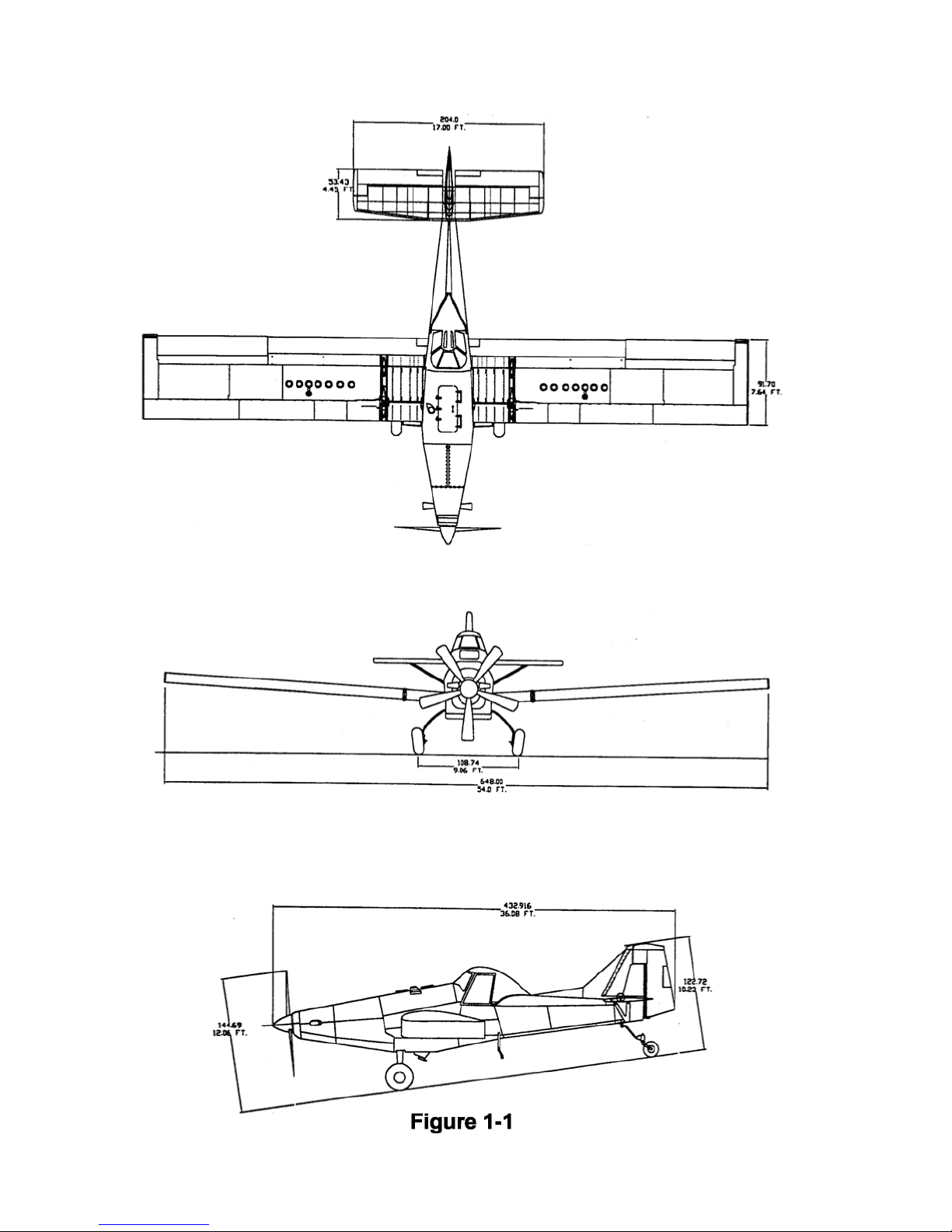
FIGURE 1-1 ................................................................................................................................10
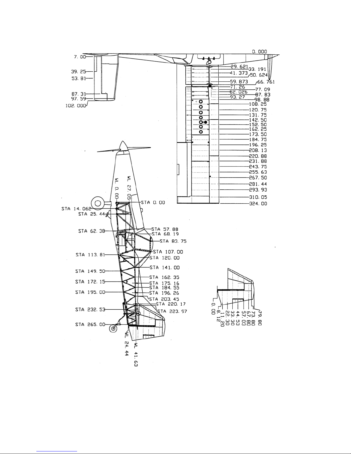
FIGURE 1-2 ................................................................................................................................11
Effective: 12/17/03 1 - 1

THRUSH AIRCRAFT INC – T660 TURBO THRUSH
AIRCRAFT MAINTENANCE MANUAL
GENERAL INFORMATION
SECTION ONE
GENERAL DESCRIPTION
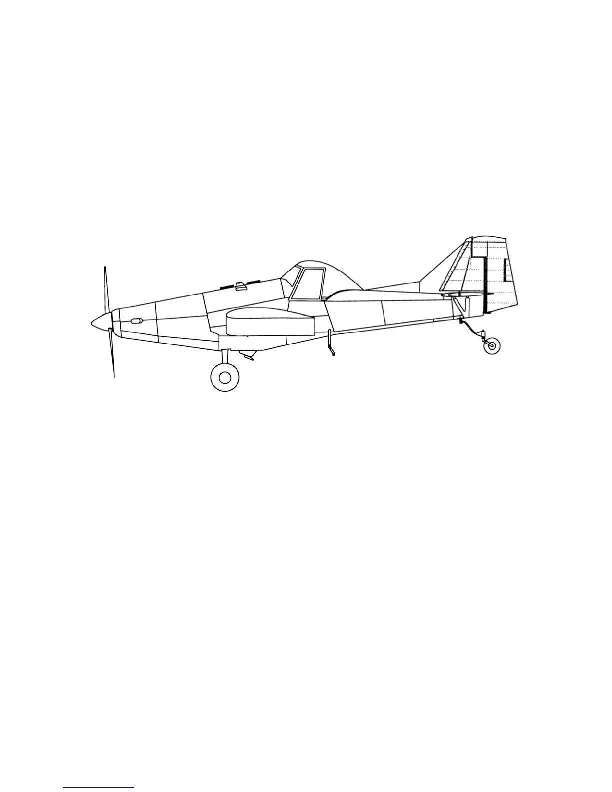
The Thrush Aircraft Inc Turbo Thrush is designed especially for agricultural flying. It is a monoplane
featuring a full cantilever low wing and all metal construction. The design and construction of the
airframe components assure all structural integrity, flight safety, and minimum maintenance
requirements. The Turbo Thrush is designed for the highest crash load factors in the industry.
Safety and reliability of operation and maximum pilot crash protection are proven and effective
features of the design. The high strength overturn structure is a proven design. The fuselage a nd
overturn structure, constructed throughout of chrome-moly steel tubing, is immensely strong in the
cockpit area.
CONTACT INFORMATION
For further information related to this manual, please contact our Product Support Manager at (229)
883-1440.
Wing Span Extended Tip 648.0 Inches (54’.00”)
Overall Length 432.9 inches (36' 0.91")
Height To Top Of Canopy 126.0 inches (10' 6.00")
Main Gear Tread 108.7 inches (9' 0.74")
Main Gear To Tail Wheel 274.20 inches (22' 10.20")
Empty Weight Equipped 6,100 pounds minimum
Maximum Weight 14,150 pounds with liquid dispersal equipment installed
PRINCIPAL DIMENSIONS
GENERAL
Effective: 12/17/03 1 - 2

THRUSH AIRCRAFT INC – T660 TURBO THRUSH
AIRCRAFT MAINTENANCE MANUAL
WING
Type Full Cantilever
Airfoil Section Naca 4412
Dihedral 3.50 Degrees
C. G. Range (See Airplane Flight Manual for pertinent data)
-Fwd Limit 24.5 Inches Aft Of Datum
-Aft Limit 30.0 Inches Aft Of Datum
(Datum Is The Leading Edge Of The Wing.)
Aileron Travel
-Up 21 Degrees ±1 Degree
-Down 17 Degrees ±1 Degree
Flap Travel Down 15 Degrees ±1 Degree
HORIZONTAL STABILIZER AND ELEVATORS
Span 204 Inches (17')
Elevator Travel
-Up 27 Degrees ±1 Degree
-Down 17 Degrees ±1 Degree
Trim Tab Travel
-Up 8 Degrees ±1 Degree
-Down 22 Degrees ±1 Degree
VERTICAL STABILIZER AND RUDDER
Rudder Travel 22 Degrees ±1 Degree
Rudder Trim Tab Travel
0 Degrees to Max 8.6 Degrees Trailing Edge
Left
1 – 3 Effective: 12/17/03

THRUSH AIRCRAFT INC – T660 TURBO THRUSH
AIRCRAFT MAINTENANCE MANUAL
AREAS
Wing 405.0 Square Feet
Aileron (Each) 23.40 Square Feet
Flaps (Each) 26.70 Square Feet
Stabilizer 39.30 Square Feet
Elevators 20.40 Square Feet
Elevator Tabs (Each) 1.30 Square Feet
Fin 10.59 Square Feet on T660-109 and subsequent
Rudder 15.55 Square Feet on T660-109 and subsequent
SUPPLIER FURNISHED COMPONENT MANUALS
MANUAL PART #
PT6A-67AG
Parts Manual 3036134
PT6A-60AG
Parts Manual 3034344
THIS SPACE INTENTIONALLY LEFT BLANK.
PT6A-45A, PT6A-45B, PT6A45R
Parts Manual 3027044
Propeller (B5P10120S) Owner’s Manual 139
Maintenance Manual
3036132
Vol. I & II
Maintenance Manual
3034342
Vol. I & II
Maintenance Manual
3027042
Vol I & II
AIRCRAFT STRUCTURES
FUSELAGE
The fuselage comprises a welded tubular steel frame, fiberglass hopper, and detachable skins. An
overturn structure forms an integral part of the fuselage frame. The frame structure, fittings,
bushings, brackets, and so forth are fabricated from 4130 chrome-moly seamless steel tubing.
As a corrosion preventative, hot linseed oil is pumped throughout the entire welded structure. On an
average, 12 gallons are pumped into the frame and 11 to 11 1/2 gallons drain out, leaving a
residual coating on all members. The exterior of the frame is sandblasted, etched, and primed,
which is followed by two coats of polyurethane paint that is resistant to chemical reaction. The
Effective: 12/17/03 1 - 4

THRUSH AIRCRAFT INC – T660 TURBO THRUSH
AIRCRAFT MAINTENANCE MANUAL
fuselage is covered with heat treated Alclad panels attached with camloc fasteners. Side skins can
be removed using only a screwdriver, thus exposing the fuselage frame for thorough cleaning and
inspection. All skins are supported clear of the fuselage tubing to prevent accumulation of corrosive
chemicals. The seams and lap joints of the skin panel support structure are sealed with a special
compound to eliminate chemical action between the mating surfaces. Each skin panel is etched,
primed, and painted before assembly to insure complete coverage. All lower fuselage skins around
the hopper opening and aft to the tail post are made of stainless steel. The skin fasteners in the
high corrosion areas are also stainless steel.
CENTER SECTION
The Center Section is a constant chord of 90 inches, all metal, and full cantilever design. The
massive main spar is of a one piece design of high strength heat treated steel and machined to
reduce weight. The spar is cad plated, primed and painted. All metal skins and ribs are constructed
from Alclad heat-treated aluminum material. The unit attaches to the fuselage and supports the
wings.
WING
The wing is a constant chord of 90 inches, all metal, and full cantilever design. The massive main
spar is a tension field beam structure constructed from Alclad webs and high strength heat-tr eated
steel caps. All wing skins, ribs, and leading edges are constructed from Alclad heat-treated material.
The leading edge structure is made especially strong to minimize denting and is riveted with
universal rivets for strength. The fuel tanks, which are located in the inboard section of the wing, are
an integral part of the structure. Close pitch riveting of the seams, substantial reinforcement, and
flexible sealants minimize chances of rupture in crash conditions. Drain holes are provided in
adjacent bays to prevent accumulation of fuel in the event of a leak. The ailerons and flaps are all
metal construction and are hinged on ball bearings. The flaps are electrically operated by push rods
and are completely sealed against chemical entry. Flap hinges are stainless steel. For the Model
S2R-T660, the outer wing panel detaches from the center wing panel by removal of four bolts.
EMPENNAGE
The horizontal stabilizer, elevator, rudder and vertical fin are an all-metal structure. All skins, ribs
and leading edges are constructed from alclad material. The movable surfaces are hinged on
sealed bearings that can be easily replaced. The rudder and the elevator have aerodynamic
balances that are protected by overhangs on the fixed surfaces.
1 – 5 Effective: 12/17/03

THRUSH AIRCRAFT INC – T660 TURBO THRUSH
AIRCRAFT MAINTENANCE MANUAL
COCKPIT
The overturn structure is exceptionally strong and welded to "hard points" in the fuselage frame.
The forward bracing supports the windshield support channels and is welded to a lateral tube that is
curved to provide more head clearance. The fiberglass canopy shell has extra thickness on the top
portion and is well attached to the extra large steel tube structure so that it will serve as a skid in
case of overturn. The large canopy doors permit easy entrance to one or both cockpits. The doors
should not be removed for flight, as the aircraft performance will be lowered. The cockpit seat belts
are anchored to the seat structure, and the shoulder harnesses are secured to a steel channel at
the bottom of the seat structure. The seats adjust vertically. The rudder pedals adjust fore and aft.
The windshield is a three-piece construction. The center section is tempered safety plate glass for
better resistance to scratching and is enclosed in a stainless steel frame. The windshield side
panels are Plexiglas and are curved to provide streamlining.
AIRCRAFT SYSTEMS
HYDRAULIC SYSTEMS
The hydraulic system consists of two master cylinders and hydraulic brake lines connecting the
master cylinders to the wheel brake cylinders. Applying toe pressure on the rudder pedals actuates
the master cylinders, which are located just aft of the pilot’s rudder pedals. A small reservoir is
incorporated within each master cylinder to supply the system with brake fluid.
POWER PLANT & PROPELLER
(Refer to manuals listed in Chart on Page 1-4 in this Section.)
The S2R-T660 Turbo Thrush is powered by the PT6, a lightweight free turbine engine incorporating
a reverse flow combustion path, is designed for aircraft propulsion use. It utilizes two counter
rotating turbine sections. One drives the compressor, and the other drives the propeller through a
reduction gearbox. The latter turbine is "free" or independent of the compressor turbine. More
recent and higher-powered models incorporate a two-stage free turbine. The PT6 has been
produced in several models and has been adapted to a multitude of uses.
The propeller has five blades mounted on a hollow hub in the front end of which is a servo-piston
that moves forward under servo-oil pressure or rearward under feather return spring pressure.
R1
Effective: 01/10/05
1 - 6

THRUSH AIRCRAFT INC – T660 TURBO THRUSH
AIRCRAFT MAINTENANCE MANUAL
There are five links from the servo-piston. One goes to each blade root, and these links transmit
forward motion of the servo-piston to the blade roots and pivot the blades in the decrease pitch
direction. When servo-piston pressure is relieved, the servo-piston moves rearward under feather
return spring pressure and pivots the blades in the increase pitch direction. This action is assisted
by centrifugal force of the counterweight on each blade root.
FUEL SYSTEM
A 230-gallon fuel supply is available for the Thrush S2R-T660. In each wing, fuel is contained inside
integral wing tanks (wet wing fuel tanks) just outboard of the center section sub-wings. The left wing
and right wing fuel tanks are interconnected through a 5 U.S. gallon header tank that is located in
the fuselage. The fuel supply lines, to the engine, are routed from the header tanks outlet finger
screen through a fuel shutoff (on/off) valve to an electric driven fuel boost pump. The electric driven
fuel boost pump discharge is then routed through a 25-micron main fuel filter to an engine driven
fuel boost pump. The electric driven fuel boost pump serves two purposes, first as a backup system
to provide continuous fuel pressure to the engines high pressure fuel pump in case the engine
driven fuel boost pump fails and secondly to provide boosted fuel pressure to the engines high
pressure fuel pump during engine starting. The aircraft’s fuel system is equipped with two fuel
filters, a ¼ inch mesh finger strainer is installed in the outlet fitting from the header tank and a 25micron, airframe supplied, main fuel filter located on the forward L/H side of the firewall. Fuel from
the aircraft fuel system enters the engines high pressure fuel pump which has two fuel filters, an 74micron inlet filter and a 10-micron discharge filter (refer to the engines appropriated maintenance
manual for pertinent maintenance details for the engine supplied filters and fuel system). The fuel
tank vent system is designed to keep the fuel spillage to a minimum. The fuel tanks are vented
through tubing connected at both the inboard and outboard ends of the individual fuel tanks to the
centrally located vent system in the fuselage. Ram air enters a vent scoop, on the fuselage, under
the left wing and pressurizes the vent system to maintain positive pressure on the fuel tanks. The
vent system is provided with two quick drains, located on the fuselage under each wing, to drain
any fuel that might happened to have got in the tanks outboard vent lines. At engine shutdown, fuel
from the flow divider/dump valve, located at the 6 o’clock position on the engines fuel nozzle
manifold, is directed to a residue fuel reservoir “EPA tank” mounted inboard on the L/H aft shin skin.
This reservoir hold approximately 3 engine shutdowns worth of fuel before the fuel will exit the
reservoirs vent system. (NOTE: This reservoir should be emptied after each engine shutdown.)
(NOTE: It is common and normal after an engine compressor Water Wash or Performance
Recovery Wash to have water or soap appear in the reservoirs’ drained waste fuel.) The fuel
quantity gauge is located on the lower left instrument panel. The fuel quantity indicating system
consists of two transmitters, one indicator gauge, and a L/H or R/H tank fuel quantity selector
switch. A transmitter, installed in each wing
1 – 7 Effective: 12/17/03

THRUSH AIRCRAFT INC – T660 TURBO THRUSH
AIRCRAFT MAINTENANCE MANUAL
tank transmits an electrical signal to the single fuel quantity indicator. The instrument reads both the
left and right fuel tanks singularly as chosen by the electrical control switch, adjacent to the fuel
quantity indicator gauge on the instrument panel. The two fuel tanks are serviced through filler ports
located on the top of both wings. The filler ports incorporate security chains to prevent the lost of the
fuel caps. Service the aircraft from refueling facilities that utilize proper ground handling equipment
and filter systems to remove impurities and water accumulations from the bulk fuel. If filtering
facilities are not available, filter the fuel through a quality high-grade chamois. Fuel tanks should be
serviced after the last flight of each day to reduce condensation and allow any entrapped water
accumulations to settle to the fuel system drains, to be removed, prior to the next flight.
Prior to the first flight of the day the header tank and fuel filter should be drained to check for the
presence of water or sediment in the fuel system. If there is a possibility, at any time, that any
tank may contain water, the header tank and fuel filter should be drained as necessary to ensure no
water exists in the fuel system. For fuel system servicing information, refer to Section Two.
LANDING GEAR, WHEELS & BRAKES
The main landing gear is made using a formed chrome-moly spring steel unit. The left Main gear
and the right main gear are symmetrical. The main wheels are 11 x 10. The spring steel
construction and design of the main gear allow for absorption of landing weight and common
stresses associated with such, thus eliminating the need for shock struts. The brake system has
individual toe brakes and individual park brakes. The use of a special N-513 compound cup in each
master cylinder permits the use of MIL-H-5606, a heavy-duty aviation hydraulic fluid. The brakes
are dual caliper disc types. The tail gear is a spring steel type and uses a 600 x 6 tailwheel.
FLIGHT CONTROLS
The flight controls are of conventional design employing extensive use of ball bearings for low
friction and smoothness of operation. The aileron and elevator controls are push rod systems and
the rudder control is through cables. The elevator trim control is actuated by a lever that moves the
tab to the desired position through push rods. The wing flaps are operated electrically and
controlled by a switch located on the left side of the cockpit. The rudder controls are interconnected
by springs to the aileron system so that a wing may be lifted with the rudder alone.
INSTRUMENTS
The standard instruments are located on three separate panels: An upper panel, a left panel, and a
Effective: 12/17/03 1 - 8

THRUSH AIRCRAFT INC – T660 TURBO THRUSH
AIRCRAFT MAINTENANCE MANUAL
right panel. The left panel contains a clock, oil temperature, hour meter, fuel pressure, oil pres sure,
air filter Delta “P”, and fuel quantity gauges. The right panel contains a voltmeter, amme ter, and
circuit breakers. The upper panel contains all engine-warning lights, torque pressure, ITT indicator,
and Gas Generator percent RPM, Propeller RPM and standard flight instrument package.
ELECTRICAL SYSTEM
The standard 24 volts and 105 amps electrical system consists of the starting system, the
navigation lights, the wiper/washer system, and the strobe lights. The landing lights, the working
lights, and the air conditioner system are optional. The landing and working lights may be installed
in the field, since the wiring for them is included in the standard wire bundle. The electrical system
obtains power from two 24-volt batteries and one starter/generator. An external power receptacle is
standard equipment and may be used for connecting a 24-volt ground power unit to the aircraft for
engine starting or maintenance. The ground start system utilizes the master relay so that startin g is
accomplished by engaging the starter switch.
AIRCRAFT WEIGHT & BALANCE
Refer to S2R-T660 Flight Manual for aircraft weight and balance information.
1 – 9 Effective: 12/17/03
THRUSH AIRCRAFT INC – T660 TURBO THRUSH
AIRCRAFT MAINTENANCE MANUAL
Effective: 12/17/03
1 - 10
THRUSH AIRCRAFT INC – T660 TURBO THRUSH
AIRCRAFT MAINTENANCE MANUAL
1 – 11 Effective: 12/17/03
Figure 1-2

THRUSH AIRCRAFT INC – T660 TURBO THRUSH
AIRCRAFT MAINTENANCE MANUAL
Section 2
SERVICING & INSPECTION
TABLE OF CONTENTS
SECTION TWO ................................................................................................................................................ 1
SERVICING .................................................................................................................................................. 3
GROUND HANDLING .................................................................................................................................. 3
TOWING ................................................................................................................................................... 3
TAXIING ................................................................................................................................................... 3
PARKING ................................................................................................................................................. 3
MOORING ................................................................................................................................................ 3
JACKING .................................................................................................................................................. 4
LEVELING ................................................................................................................................................ 4
COLD WEATHER OPERATION .................................................................................................................. 4
COLD WEATHER MAINTENANCE HINTS ............................................................................................. 4
GROUND EMERGENCY PROCEDURES ................................................................................................... 5
ENGINE FIRES ........................................................................................................................................ 5
ELECTRICAL FIRES ................................................................................................................................ 6
GROUND OPERATION OF ENGINE .......................................................................................................... 6
BEFORE STARTING ENGINE ................................................................................................................. 6
STARTING ENGINE ................................................................................................................................. 7
ENGINE OPERATIONAL CHECK ........................................................................................................... 8
SYSTEM AND COMPONENT SERVICING .................................................................................................8
HYDRAULIC SYSTEM ............................................................................................................................. 9
ENGINE OIL SYSTEM ............................................................................................................................. 9
FUEL SYSTEM ....................................................................................................................................... 13
DEFU ELI NG ......................................................................................................................................... 15
INDUCTION SYSTEM ............................................................................................................................ 16
POWER PLANT INTERNAL CLEANING ............................................................................................... 16
LANDING GEAR, WHEELS & BRAKES .................................................................................................... 17
TI RES ....................................................................................................................................................17
BRAKE BLEEDING ................................................................................................................................ 17
I NSPECTION ......................................................................................................................................... 17
INSPECTION CHECK LIST ................................................................................................................... 17
INSPECTION CHART ............................................................................................................................. 19
ENGINE EXTERNALS ............................................................................................................................... 21
ENGINE OIL SYSTEM ...............................................................................................................................22
ENGINE FUEL SYSTEM ............................................................................................................................ 24
IGNITION SYSTEM .................................................................................................................................... 25
PNEUMATIC SYSTEM .............................................................................................................................. 25
AIRFRAME FUEL SYSTEM ....................................................................................................................... 25
MAIN LANDING GEAR .............................................................................................................................. 26
TAIL GEAR ................................................................................................................................................. 27
FUSELAGE SKINS .................................................................................................................................... 28
HOPPER .................................................................................................................................................... 28
WI NGS ...................................................................................................................................................... 29
FUSELAGE FRAME ................................................................................................................................... 30
CONTROL SYSTEMS ................................................................................................................................ 30
METAL EMPENNAGE ............................................................................................................................... 32
AILERONS AND FLAPS ............................................................................................................................ 33
COCKPIT .................................................................................................................................................... 34
ELECTRICAL SYSTEM ............................................................................................................................. 34
Effective: 12/17/03 2- 1

THRUSH AICRAFT INC - T660 TURBO THRUSH
AIRCRAFT MAINTENANCE MANUAL
CORROSION CONTROL ........................................................................................................................36
WINDSHIELD ..........................................................................................................................................37
HOPPER REPAIR ...................................................................................................................................37
FUEL TANK REPAIR ..............................................................................................................................37
BATTERY MAINTENANCE ....................................................................................................................37
LUBRICATION ........................................................................................................................................38
Effective: 12/17/03
2 - 2

f
THRUSH AIRCRAFT INC - T660 TURBO THRUSH
AIRCRAFT MAINTENANCE MANUAL
SECTION TWO
SERVICING & INSPECTION
Standard procedure for ground handling, servicing, inspection, airframe maintenance, lubrication,
and storage are included in this Section. Adherence to these procedures on a scheduled basis can
save many hours of maintenance and aircraft down time. When a system component requires
service or maintenance other than that outlined in this Section, refer to the applicable Section o
this manual for complete information.
GROUND HANDLING
TOWING
Movement of the aircraft on the ground may be accomplished as follows:
A. Pull and guide the aircraft by means of a tow bar with the tail wheel unlocked.
B. Attach a rope harness to the main gear when there is a need to tow the aircraft
forward through snow or over soft and/or muddy ground.
TAXI I NG
Before attempting to taxi the aircraft, maintenance personnel should be checked out by qualified
personnel. When it is determined that the propeller area is clear, apply the power to start the taxi
roll and perform the following:
A. Push the stick full forward to unlock the tail wheel.
B. Taxi a few feet and check the brake operation.
C. While taxiing, make slight turns to determine that the tail wheel steering is operative.
D. Avoid taxiing over groun d of loose stones, gravel, or other loose material that may
cause foreign object damage to the propeller or to other aircraft in the area.
E. You may taxi with the power lever in the Beta region to govern ground speed. Observe
all engines operating limits.
PARKING
Head the aircraft into the wind and set the parking brake. Do not set the parking brake during cold
wet weather because the accumulated moisture may freeze in the brakes. Do not set the parking
brake if the brakes are overheated. Install the internal control lock. Place the chocks under each
main wheel.
Effective: 12/17/03 2- 3

r
THRUSH AICRAFT INC - T660 TURBO THRUSH
AIRCRAFT MAINTENANCE MANUAL
Park aircraft as previously outlined. In winds up to 20 knots, secure the aircraft at the wing tie down
rings. For winds above 20 knots, tie the tail and main gear as well as the wings. Install external
control surface locks. Be sure to tie the propeller down to prevent it from windmilling with zero oil
pressure. The aircraft should be placed in a hangar when wind velocity is predicted to exceed 50
knots. When mooring aircraft, use 3/4-inch manila or nylon rope. A clove hitch or other anti-slip knot
should be employed. If a manila rope is used for tie down, allow enough slack to compensate fo
contraction of the rope fiber without damaging the aircraft.
Jack points are provided on each main spar and located at wing stations 191 & 265.23. When using
the jack points to lift the aircraft, all hopper loads should be removed. (Fig. 2-1) A jack point is also
provided on the tail wheel trunnion attach fitting on the lower left longeron.
The aircraft may be leveled by raising the tail to an approximate level flight position and by
MOORING
JACKI NG
LEVELING
supporting the tail on a stable jack or platform. Adjust the height of the tail wheel until the left-hand
lower longeron located under the cockpit is level.
COLD WEATHER OPERATION
Aircraft operation in cold weather creates a need for additional maintenance practices and operating
procedures that are not required in moderate temperatures. Whenever possible, shelter the aircraft i n
a heated hangar to prevent frost, ice, or snow accumulation that requires added maintenance time
to remove. These weather elements, if allowed to accumulate only a fraction of an inch in thickness
on the critical airfoils and control surfaces, seriously degrade aircraft lift and flight control
effectiveness. The possibility of aircraft system failures is increased when the aircraft is parked
where wind driven snow or freezing rain can be forced into various openings of the aircraft. If the
aircraft is to be moored outside in extreme cold, the battery should be kept fully charged to prevent
freezing. Make certain that all vents, air inlets, and so forth are covered.
Locating the aircraft inside a heated hanger is the most effective method of preheating the aircraft.
The use of an external power unit is recommended to conserve the battery.
2 - 4 Effective: 12/17/03

A
r
THRUSH AIRCRAFT INC - T660 TURBO THRUSH
AIRCRAFT MAINTENANCE MANUAL
The information that follows is intended only for the purpose of supplementing the existing
information in this manual when operating the aircraft in cold weather. Keeping the aircraft in top
maintenance condition during cold weather cannot be over stressed.
The battery should be maintained at full charge during cold weather to prevent freezing. After adding
water to the battery in freezing temperatures, charge the battery to mix the water and electrolyte.
frozen battery may explode when subjected to a high charge rate. Corrosive damage to the area
adjacent to an exploded battery will result if the electrolyte solution is not removed immediately.
Instructions for removing spilled electrolyte are provided in this Section. The battery should be
removed and stored in a warm place if the aircraft is to remain idle for an extended period of time.
In the fuel system, condensation is more likely to occur in cold weather due to a more rapid and
positive division of moisture content from other fuel properties. If at all possible, use fueling facilities
that filter moisture from the fuel. If fueling facilities with filters are not available, filter the fuel through a
good quality chamois. Fill the tanks with correct grade of fuel as soon as possible after landing to
reduce the possibility of condensation and ice formation in the tanks. Fuel extracted from fuel heade
COLD WEATHER MAINTENANCE HINTS
tank drain before starting deserves a closer examination when the aircraft is being operated in cold
weather.
Cold weather operation demands procedures that are in addition to normal Post Flight Maintenance
Procedures. Fill the fuel tanks immediately after flight. If shelter is not available, tie the aircraft down
and install covers on all vents, openings, and so forth as required.
GROUND EMERGENCY PROCEDURES
Emergency procedures must be accomplished as rapidly as possible, should an emergency arise. It
is suggested that steps pertaining to each emergency be committed to memory in order to
accelerate the procedure and minimize any possible damage.
ENGINE FIRES
The following Dry Motoring Run procedure is used to clear an engine at any time when deemed
necessary to remove internally trapped fuel and vapor or when there is evidence of a fire within the
engine. Air that passes through the engine serves to purge fuel, vapor, or fire from the combustion
sections, the gas generator turbine, the power turbine, and the exhaust system.
Effective: 12/17/03 2- 5

THRUSH AICRAFT INC - T660 TURBO THRUSH
AIRCRAFT MAINTENANCE MANUAL
A. Fuel Condition Lever - Cut Off
B. Ignition Switch - Off
C. Master Switch - On
D. Fuel Shutoff Valve - On
E. Fuel Auxiliary Pump Switch - On This will provide
lubrication for the engine-driven fuel pump.
F. Engine Starter Switch – On
*** WARNING ***
If the fire persists as indicated by the sustained
interturbine temperature, close the fuel system
shutoff valve at this point and continue motoring.
G. Maintain the starter operation for the desired duration. The maximum starter duration is
3 minutes.
H. Engine Starter Switch - Off
I. Fuel Auxiliary Pump Switch - Off
J. Fuel Shutoff Valve - Off
K. Master Switch - Off
L. Allow a 5-minute cooling period for the starter before going any further with the starting
operation.
ELECTRICAL FIRES
Circuit breakers will automatically trip and stop the current flow to a shorted circuit. However, as a
safety precaution in the event of an electrical fire, turn the battery switches to off. Use a fire
extinguisher approved for electrical fires to extinguish the flame.
GROUND OPERATION OF ENGINE
BEFORE STARTING ENGINE
Visually check the aircraft for general condition. Verify that all camlocs on the skin panels are
fastened. Remove all accumulations of frost, ice, or snow in cold weather from the wing, the tail,
and the control surfaces. Check that the control surfaces contain no internal accumulations of ice.
Remove the inlet and exhaust covers, if fitted. If night flight is planned, check the operation of all
lights and have a flashlight available.
2 - 6 Effective: 12/17/03

r
THRUSH AIRCRAFT INC - T660 TURBO THRUSH
AIRCRAFT MAINTENANCE MANUAL
After a complete visual inspection has been accomplished, the following checklist may be used for the
external prestart check. The aircraft should be headed into the wind and should have the wheel
chocks in place.
A. A fire extinguisher must be readily available in the event of an engine fire.
B. Check the engine oil level. Assure that the oil system has been serviced with the correct
grade of oil.
C. Verify that the internal control lock has been removed and that the controls operate freely.
D. Set the parking brake.
E. Check the fuel quantity in both tanks.
F. Set the trim tabs for takeoff.
G. Clear the area of all personnel.
STARTING ENGINE
Use the following procedure to start the PT6A engine.
A. Battery and Generator Switches - On
B. Power Lever - Idle
C. Propeller Lever - Feather
D. Fuel Condition Lever - Cut Off
E. Fuel Shutoff Valve – On
F. Fuel Auxiliary Pump Switch - On
G. Fuel Inlet Pressure Indicator - Check 5 PSI Minimum
H. Engine Starter Switch - On
The minimum speed to obtain a satisfactory light is 13% Ng.
I. After approximately 5 seconds of motoring at the sta bilize d gas generator speed, turn the
Ignition Switch On and move the Condition Lever to the Ground (low) Idle position.
J. Observe that the engine accelerates normally to idle RPM and the maximum allowable
Inter-turbine temperature-starting limit is not exceeded.
** CAUTION **
Whenever the gas generator fails to light up within 10 seconds after moving the fuel condition lever to the
ground (low) idle position: fuel condition lever – idle cutoff, ignition switch - off, starter – off. Allow a 30second fuel draining period that is followed by a 15-second dry motoring run before attempting anothe
start. If for any reason a starting attempt is discontinued, allow the engine to come to a complete stop and
then accomplish a Dry Motoring Run as described on page 2-5 under Engine Fires. That procedure is also
referred to as Dry Motoring run.
Effective: 12/17/03 2- 7

THRUSH AICRAFT INC - T660 TURBO THRUSH
AIRCRAFT MAINTENANCE MANUAL
When the engine attains idle rpm:
K. Engine Starter Switch and Ignition Switch - Off
L. Oil Pressure - Check 60 PSIG Minimum
M. Fuel Auxiliary Pump - Off
N. Fuel Pressure from Engine Driven Pump - Check 5 PSI Minimum
O. Generator Charging – Check
ENGINE OPERATIONAL CHECK
** CAUTION **
Fill hopper and hold the elevator control firmly full up during all
high power ground operations to keep aircraft from nosing over.
Refer to Section Four for specific operational checks and/or Pratt & Whitney Maintenance Manual.
Before proceeding with a ground run up, be sure that the propeller system is purged by feathering
the propeller once or twice with the power control lever in idle position.
The following procedure should be used to check the propeller overspeed governor.
A. Place the propeller lever in full increase RPM position (forward).
B. Turn prop test switch on.
C. Increase RPM with the power lever until governing occurs. This should oc cur at 1598
±20 RPM. (In no case should any engine limitations be exceeded.)
D. Reduce power back to idle.
E. Turn prop test switch off.
*NOTE*
If RPM is not governed at 1598 ±20 RPM with the prop test switch
on, consult Section IV of this manual for adjustment of the
overspeed-governor.
SYSTEM AND COMPONENT SERVICING
Servicing procedures contained in this Section are confined to those maintenance actions that
occur with routine frequency and require a reasonably short period of time to accomplish. Servicing
practices and maintenance to aircraft systems and components that require less frequent attenti on
are contained in the appropriate Section of this manual.
2 - 8 Effective: 12/17/03

r
r
A
THRUSH AIRCRAFT INC - T660 TURBO THRUSH
AIRCRAFT MAINTENANCE MANUAL
The hydraulic system consists of two master brake cylinders and the necessary hydraulic lines
connecting the master cylinders to the wheel brake cylinders. Applying toe pressure on the rudde
pedals actuates the master cylinders, which are located just aft of the pilot’s rudder pedals. Refer to
Section Six (pages 6-10 thru 6-13) for brake servicing procedures.
The oils that are specified for the lubrication system are detailed in the Pratt and Whitney Canada
Service Bulletin 13001. All oils listed in the bulletin are approved for flight operation. It is
recommended for all turbo aircraft that the oil should be changed every 400 hours. The oil system
contains 13 U.S. quarts.
In cases where oils that are approved are not available, an operator must obtain prior approval o
recommendations for use of substitution oil from the Service Department, Pratt and Whitney
Canada Corp, 1000 Marie-Victorin, Longueuil, Quebec, Canada J4K 1A1.
. OIL LEVEL CHECK To avoid overfilling of oil tank, and high oil consumption, an oil level check is
HYDRAULIC SYSTEM
ENGINE OIL SYSTEM
recommended within 30 minutes after shutdown. Ideal interval is 15 to 20 minutes. If more
than 30 minutes has passed, and the dipstick indicates that oil is needed, start the engine and
run at ground idle (low idle) for five minutes, and recheck oil level.
1. Unlock the filler cap and dipstick from the filler neck at the eleven o'clock
position on the accessory gearbox and remove the filler cap.
** CAUTION **
Do not mix different brands, viscosity’s, or types of oil since their
chemical structures may make them incompatible. If different types of
oil become mixed, drain and flush the system. Refill with new oil.
2. Check the oil tank contents against the markings on the dipstick. Service
as required.
Effective: 12/17/03 2- 9

f
f
THRUSH AICRAFT INC - T660 TURBO THRUSH
AIRCRAFT MAINTENANCE MANUAL
* NOTE *
3. If the engine is nose high or nose low, compensation must be made to avoid over or
under servicing.
B. If the oil level is too low to register on the dipstick due to possible excessive consumption or i
low or fluctuating pressures have been recorded, refer to Troubleshooting - Lubrication
Problems in the Pratt and Whitney Maintenance Manual for the action to be taken. After that
The graduations on the dipstick indicate the oil level in U.S. quarts
below maximum capacity of the oil tank. The normal cold oil level is the
Maximum Cold mark on the dipstick. The normal hot level is Maximum
Hot mark on the dipstick. A dipstick reading of 3 will indicate that the
system requires 2 U.S. quarts to replenish to normal level if the oil is
cold. If the oil is hot, it will take 3 U.S. quarts to replenish.
has been accomplished, proceed as follows to check the oil level.
1. Fill the oil tank to the appropriate normal level. Record the quantity of oil added to
the system.
2. Install the filler cap and dipstick. Ensure that the cap is locked securely.
3. Run the engine idle for approximately 5 minutes.
4. Check the oil level.
5. Check the oil filter per appli cabl e Pratt & Whitney Maintenance Manual.
C. On engines which have remained stationary for a period of 12 hours or more, proceed as follows
to check the oil level.
1. Start the engine and run at idle speed for a minimum of 2 minutes.
2. Feather the propeller.
3. Shut down the engine.
4. Check the oil level.
D. Recommendations for oil change intervals are based on the performance of specific brands o
oil, specific types of oil, specific engine models, and specific operating criteria. General oil
change intervals may be extended periodically and will be reflected by revisions to the Pratt
and Whitney Engine Service Bulletin 13001. Permission for extension of oil drain intervals may
be granted to operators through monitoring programs, which are conducted by most
2 - 10 Effective: 12/17/03

r
r
THRUSH AIRCRAFT INC - T660 TURBO THRUSH
AIRCRAFT MAINTENANCE MANUAL
major oil companies that have been approved by Pratt and Whitney Canada. Service Bulletin
13001 will be revised periodically to include newly approved oils. Refer to Figure 2-8 for the
locations called out in the following procedure.
1. Place suitable containers or drip pan under the engine.
2. Remove lockwire from the main oil tank’s drain plug #6 from boss on compresso
inlet case. Remove drain plug. Discard the preformed packing. Or drain oil at drain
port on left shin skin (on aircraft equipped with quick drain).
3. Remove the rear case drain plug #2 from the six o'clock position on the rear face of
the accessory gearbox housing. Discard the preformed packing.
4. Remove the chip detector #3 from the six o'clock position on the reduction gearbox
front case. Discard the preformed packing.
5. Examine the drained oil for the presence of foreign matter.
E. Refill the oil tank by accomplishing the following procedures.
1. Install the chip detector #3 with new preformed packing on the reduction gearbox.
Torque chip detector body #3 45 to 55 lb. in. and lockwire.
2. Install rear case drain plug #2 with new preformed packing in the accessory
gearbox housing. Tighten and torque to 215 to 240 lb. in. and lockwire.
3. Install the drain plug #6 with the new preformed packing in the bottom of the ai
inlet case. Or simply install a cap on the drain port on the left shin skin (on aircraft
equipped with quick drain) and lockwire.
4. Fill the oil tank with the specified oil to the level of maximum graduation on the
dipstick.
F. Install the filler cap and dipstick assembly in the oil tank. Ensure that the cap is locked securely.
1. Start the engine and run at idle for approximately 2 minutes to circulate the oil
through the system.
2. Feather the propeller.
3. Shut down the engine.
4. Check the oil level in the tank. Replenish, as required, to the normal level on the
dipstick.
5. Install the filler cap and dipstick assembly in the oil tank. Ensure that the cap is
locked securely.
Effective: 12/17/03 2- 11

THRUSH AICRAFT INC - T660 TURBO THRUSH
AIRCRAFT MAINTENANCE MANUAL
G. If an engine is to be operated with an oil brand or type that differs from that on which it
previously operated or if the oil system has been contaminated by other than metallic matter,
the oil system should be flushed by following the steps below.
1. Place suitable containers or drip pan under the engine.
2. Remove the oil drain plug or chip detector from the reduction gearbox and the
plugs from the inlet case and the accessory gearbox housing.
** CAUTION **
Limit the engine rotation to a minimum time
which is required to accomplish the complete
draining. Also observe the starter operating
limitations.
3. With the drains open, place the starting control lever to cutoff and the ignition
switch to off. Motor the engine with the starter only to allow the scavenge pumps
to clear all lubricating oil.
4. Reinstall all drain plugs and the chip detector.
5. Refill the engine oil tank with new type oil.
6. Start the engine and run at idle spe ed for a minimum of two minutes.
7. Feather the propeller.
8. Shut down the engine.
9. Repeat Steps 1. through 3.
10. Remove the main oil filter. Clean or replace the filter and reinstall.
11. Remove the reduction gearbox oil strainer and clean. Reinstall the strainer.
12. Reinstall all engine drain plugs and the chip detector. Tighten, torque, and
lockwire.
13. Repeat Steps 5. through 8.
14. Check the oil levels and replenish, as necessary.
15. Install the filler cap and dipstick assembly in the filler tube. Ensure that the cap is
correctly installed and locked.
2 - 12 Effective: 12/17/03
 Loading...