

Thrush Aircraft S2RHG-T65 TURBO THRUSH Maintenance Manual
THRUSH AIRCRAFT, INC – MODEL S2RHG-T65 TURBO THRUSH
AIRCRAFT MAINTENANCE MANUAL
AIRCRAFT MAINTENANCE MANUAL
SINGLE AND DUAL COCKPIT
Model S2RHG – T65
Serial Numbers T65HG – 011 & Up, T65HG – 013 DC & Up
Manual Number: T65HG-2
Issued May 5, 2004
Revised September 16, 2005
Manufacturer’s Serial Number: ____________________________________________
Registration Number: _________________________ ___________________________
Thrush Aircraft Inc.
P. O. Box 3149
300 Old Pretoria Road
Albany, GA 31706
Telephone: 229-883-1440
Fax: 229-436-4856
Effective: 09/16/05 i

THRUSH AIRCRAFT, INC – MODEL S2RHG-T65 TURBO THRUSH
AIRCRAFT MAINTENANCE MANUAL
LOG of PAGES
Page Date
i .......................................... 09/16/05
ii .......................................... 09/16/05
iii .......................................... 09/16/05
iv .......................................... 09/16/05
v .......................................... 05/25/05
vi .......................................... 09/16/05
vii .......................................... 09/16/05
viii .......................................... 09/16/05
Page Date
1 .......................................... 09/16/05
2 .......................................... 09/16/05
3 .......................................... 09/16/05
4 .......................................... 05/05/04
5 .......................................... 09/16/05
6 .......................................... 05/05/04
7 .......................................... 09/16/05
8 .......................................... 05/05/04
9 .......................................... 05/05/04
Page Date
1 .......................................... 09/16/05
2 .......................................... 09/16/05
3 .......................................... 05/05/04
4 .......................................... 05/05/04
5 .......................................... 05/05/04
6 .......................................... 05/05/04
7 .......................................... 05/05/04
8 .......................................... 09/16/05
9 .......................................... 05/05/04
10 .......................................... 05/05/04
11 .......................................... 05/05/04
12 .......................................... 09/16/05
13 .......................................... 09/16/05
14 .......................................... 05/05/04
15 .......................................... 05/05/04
16 .......................................... 05/05/04
17 .......................................... 05/05/04
18 .......................................... 05/05/04
19 .......................................... 05/25/05
20 .......................................... 05/25/05
21 .......................................... 05/05/04
22 .......................................... 05/25/05
23 .......................................... 05/25/05
24 .......................................... 05/05/04
25 .......................................... 05/05/04
26 .......................................... 05/25/05
27 .......................................... 05/05/04
28 .......................................... 05/05/04
29 .......................................... 05/05/04
INTRODUCTION
SECTION 1
GENERAL
INFORMATION
SECTION 2
SERVICING &
INSPECTION
(Continued)
Page Date
30 .......................................... 05/05/04
31 .......................................... 05/05/04
32 .......................................... 05/05/04
33 .......................................... 05/05/04
34 .......................................... 05/05/04
35 .......................................... 05/05/04
36 .......................................... 05/05/04
37 .......................................... 05/05/04
38 .......................................... 05/05/04
39 .......................................... 05/05/04
40 .......................................... 05/05/04
41 .......................................... 05/05/04
42 .......................................... 05/05/04
43 .......................................... 05/05/04
44 .......................................... 09/16/05
45 .......................................... 05/05/04
Page Date
1 .......................................... 05/05/04
2 .......................................... 05/05/04
Page Date
1 .......................................... 09/16/05
2 .......................................... 09/16/05
3 .......................................... 05/05/04
4 .......................................... 05/05/04
5 .......................................... 05/05/04
6 .......................................... 05/05/04
7 .......................................... 05/05/04
8 .......................................... 05/05/04
9 .......................................... 05/05/04
10 .......................................... 05/05/04
11 .......................................... 05/05/04
12 .......................................... 05/05/04
13 .......................................... 05/05/04
14 .......................................... 05/05/04
15 .......................................... 05/05/04
16 .......................................... 05/05/04
17 .......................................... 05/05/04
18 .......................................... 05/05/04
19 .......................................... 05/05/04
20 .......................................... 05/05/04
21 .......................................... 05/05/04
22 .......................................... 05/05/04
23 .......................................... 05/05/04
24 .......................................... 05/05/04
25 .......................................... 09/16/05
26 .......................................... 09/16/05
SECTION 2
SERVICING &
INSPECTION
SECTION 3
HYDRAULICS
SECTION 4
POWERPLANT &
PROPELLER
ii Effective: 09/16/05

THRUSH AIRCRAFT, INC – MODEL S2RHG-T65 TURBO THRUSH
AIRCRAFT MAINTENANCE MANUAL
LOG of PAGES
(Continued)
Page Date
27 .......................................... 09/16/05
28 .......................................... 05/05/04
29 .......................................... 09/16/05
30 .......................................... 05/05/04
31 .......................................... 05/05/04
32 .......................................... 05/05/04
33 .......................................... 05/05/04
34 .......................................... 05/05/04
35 .......................................... 05/05/04
36 .......................................... 05/05/04
37 .......................................... 05/05/04
38 .......................................... 05/05/04
39 .......................................... 05/05/04
40 .......................................... 05/05/04
Page .......................................... Date
1 .......................................... 09/16/05
2 .......................................... 09/16/05
3 .......................................... 09/16/05
4 .......................................... 05/05/04
5 .......................................... 09/16/05
6 .......................................... 05/05/04
7 .......................................... 05/05/04
8 .......................................... 05/25/05
9 .......................................... 05/05/04
10 .......................................... 05/25/05
11 .......................................... 05/05/04
12 .......................................... 09/16/05
13 .......................................... 09/16/05
14 .......................................... 05/05/04
15 .......................................... 05/05/04
16 .......................................... 09/16/05
Page Date
1 .......................................... 09/16/05
2 .......................................... 09/16/05
3 .......................................... 05/05/04
4 .......................................... 09/16/05
5 .......................................... 09/16/05
6 .......................................... 09/16/05
7 .......................................... 05/25/05
8 .......................................... 05/25/05
9 .......................................... 05/25/05
10 .......................................... 05/05/04
11 .......................................... 05/05/04
12 .......................................... 05/25/05
13 .......................................... 05/25/05
14 .......................................... 05/25/05
SECTION 4
POWERPLANT &
PROPELLER
SECTION 5
FUEL SYSTEM
SECTION 6
LANDING GEAR,
WHEELS & BRAKES
Page Date
15 .......................................... 05/25/05
16 .......................................... 05/05/04
17 .......................................... 05/05/04
18 .......................................... 05/05/04
19 .......................................... 05/05/04
20 .......................................... 05/05/04
21 .......................................... 05/05/04
22 .......................................... 09/16/05
23 .......................................... 05/25/05
24 .......................................... 05/25/05
25 .......................................... 05/25/05
26 .......................................... 05/25/05
27 .......................................... 05/25/05
28 .......................................... 05/25/05
29 .......................................... 05/25/05
30 .......................................... 09/16/05
31 .......................................... 09/16/05
Page Date
1 .......................................... 09/16/05
2 .......................................... 09/16/05
3 .......................................... 09/16/05
4 .......................................... 05/05/04
5 .......................................... 05/05/04
6 .......................................... 05/05/04
7 .......................................... 05/05/04
8 .......................................... 05/05/04
9 .......................................... 05/05/04
10 .......................................... 05/05/04
11 .......................................... 05/05/04
12 .......................................... 09/16/05
13 .......................................... 09/16/05
14 .......................................... 09/16/05
15 .......................................... 09/16/05
16 .......................................... 05/05/04
17 .......................................... 05/05/04
18 .......................................... 05/05/04
19 .......................................... 05/05/04
20 .......................................... 05/05/04
21 .......................................... 05/05/04
22 .......................................... 05/05/04
23 .......................................... 05/05/04
24 .......................................... 05/05/04
25 .......................................... 05/05/04
26 .......................................... 09/16/05
27 .......................................... 09/16/05
28 .......................................... 09/16/05
29 .......................................... 09/16/05
30 .......................................... 09/16/05
31 .......................................... 09/16/05
32 .......................................... 09/16/05
SECTION 6
LANDING GEAR,
WHEELS & BRAKES
(Continued)
SECTION 7
FLIGHT CONTROLS
Effective: 09/16/05 iii

THRUSH AIRCRAFT, INC – MODEL S2RHG-T65 TURBO THRUSH
AIRCRAFT MAINTENANCE MANUAL
LOG of PAGES
Page
33 .......................................... 09/16/05
34 .......................................... 09/16/05
35 .......................................... 09/16/05
36 .......................................... 09/16/05
37 .......................................... 09/16/05
38 .......................................... 09/16/05
39 .......................................... 09/16/05
40 .......................................... 09/16/05
41 .......................................... 05/05/04
42 .......................................... 05/05/04
Page Date
1 .......................................... 09/16/05
2 .......................................... 05/05/04
3 .......................................... 05/05/04
4 .......................................... 05/05/04
5 .......................................... 05/05/04
6 .......................................... 05/05/04
7 .......................................... 05/05/04
8 .......................................... 05/05/04
9 .......................................... 05/05/04
10 .......................................... 05/05/04
11 .......................................... 05/05/04
12 .......................................... 05/05/04
13 .......................................... 05/05/04
14 .......................................... 09/16/05
15 .......................................... 09/16/05
16 .......................................... 05/05/04
17 .......................................... 05/05/04
Page Date
1 .......................................... 09/16/05
2 .......................................... 05/05/04
3 .......................................... 05/05/04
4 .......................................... 05/05/04
5 .......................................... 05/05/04
6 .......................................... 05/05/04
7 .......................................... 05/05/04
8 .......................................... 05/05/04
9 .......................................... 05/05/04
10 .......................................... 05/05/04
Page Date
1 .......................................... 09/16/05
2 .......................................... 09/16/05
3 .......................................... 05/05/04
4 .......................................... 05/05/04
5 .......................................... 05/05/04
SECTION 7
FLIGHT CONTROLS
(Continued)
SECTION 8
INSTRUMENTS
SECTION 9
DISPERSAL SYSTEMS
SECTION 10
ELECTRICAL
SYSTEM
Date
Page
6 .......................................... 05/05/04
7 .......................................... 05/05/04
8 .......................................... 05/05/04
9 .......................................... 05/05/04
10 .......................................... 05/05/04
11 .......................................... 09/16/05
12 .......................................... 09/16/05
13 .......................................... 09/16/05
14 .......................................... 09/16/05
15 .......................................... 09/16/05
16 .......................................... 09/16/05
17 .......................................... 09/16/05
18 .......................................... 09/16/05
19 .......................................... 09/16/05
21 .......................................... 09/16/05
22 .......................................... 09/16/05
23 .......................................... 09/16/05
24 .......................................... 09/16/05
25 .......................................... 09/16/05
26 .......................................... 09/16/05
27 .......................................... 09/16/05
28 .......................................... 09/16/05
29 .......................................... 09/16/05
30 .......................................... 09/16/05
31 .......................................... 09/16/05
32 .......................................... 09/16/05
33 .......................................... 09/16/05
34 .......................................... 09/16/05
35 .......................................... 09/16/05
36 .......................................... 09/16/05
37 .......................................... 09/16/05
38 .......................................... 09/16/05
39 .......................................... 09/16/05
40 .......................................... 09/16/05
41 .......................................... 09/16/05
42 .......................................... 09/16/05
43 .......................................... 09/16/05
44 .......................................... 09/16/05
45 .......................................... 09/16/05
46 .......................................... 09/16/05
47 .......................................... 09/16/05
47 .......................................... 09/16/05
48 .......................................... 09/16/05
49 .......................................... 09/16/05
50 .......................................... 09/16/05
Page Date
1 .......................................... 05/05/04
2 .......................................... 05/05/04
SECTION 10
ELECTRICAL
SYSTEM
(Continued)
SECTION 11
AIRWORTHINESS
LIMITATIONS
Date
iv Effective: 09/16/05

THRUSH AIRCRAFT, INC – MODEL S2RHG-T65 TURBO THRUSH
AIRCRAFT MAINTENANCE MANUAL
LOG OF REVISIONS
Rev.
No.
Acceptance Date
NEW JUL 26, 2004 ALL ALL NEW BOOK C. Lorenzen
FAA
Section Pages Description of Revision
FAA
Accepted
R1
05/25/05
Prelude
1
2
4
5
6
7
i
ii, iii, iv
vi
6
24
25
27,28
32
52
32, 36
35
9
11
1, 3, 4, 5,
6, 6a
10, 11, 12,
12a, 12b
19, 19a,
20, 20a,
22, 22a
13, 14
39
Revise cover.
Revise log of pages.
Revise log of Revisions.
Typo, toe instead of to.
Change inspection procedure.
Change inspection intervals for FCU
vent.
Added more detailed inspection for tail
gear.
Change inspection interval for control
stick bolt inspection.
P/N typo, MS21044N instead of
MS20144N, added MS21046 and
MS21245.
Propeller blade typo, changed to
M10876AS instead of AN.
Typo, -65AR instead of-67AR.
P/N typo, should be CS3204 instead of
CS3024.
Change caution pressure.
Updated tail gear servicing information.
Added servicing information on metallic
brakes.
Updated and added tail gear and brake
illustrations.
Reword sentence, change vertical fin
installation procedure.
P/N typo, changed to AN960-716
washer, MS21042-7 Nut.
C. Lorenzen
Effective: 05/25/05 v

Rev.
No.
THRUSH AIRCRAFT, INC – MODEL S2RHG-T65 TURBO THRUSH
FAA
Acceptance Date
AIRCRAFT MAINTENANCE MANUAL
LOG OF REVISIONS
Section Pages Description of Revision
FAA
Accepted
R2
Forward
Section
1
Section
2
Section
4
i
ii-iv
vi & vii
viii
1
2
3
5
6
1&2
8
12
13
44
1&2
3
25
26
27
29
Revised Cover Sheet
Revised Log of Pages
Added R2 Log of Revisions
Added paragraph
Updated Table of Contents
Added phone ext., added dual
cockpit aft CG limit
Updated wing area for extension
Reworded Cockpit to reflect dual
cockpit. Corrected wing tank
location
Corrected wheel size
Updated Table of Contents
Added P & W Service phone #
Corrected fuel specifications,
improved description of fuel drains
Added Caution
Revised Torque Chart
Updated Table of Contents
Added dual cockpit engine
statement
Clarified wording
Corrected figure reference
Clarified chart reference
Corrected max continuous HP
Section
5
Section
6
1
2
3
5
12
13
16
1&2
4
5
6
15 & 16
22
30 & 31
Updated Table of Contents
Deleted redundant wording,
clarified fuel gauge operation
Added specific drain instructions
Re-formatted chart for clarity
Added Figure reference
Changed Note to Caution
Added Figure
Updated Table of Contents
Changed sentence to Warning
Expanded instructions in H. & B.
Added Warning to C.
Added instructions in K.
Added C., sealing instructions
Consolidated Brake Lining
Conditioning Procedures
Updated Figure 6-1
Added new Figures
vi Effective: 09/16/05

Rev.
No.
FAA
Acceptance Date
THRUSH AIRCRAFT INC
MODEL S2RHG-T65 TURBO THRUSH
AIRPLANE MAINTENANCE MANUAL
Section Pages Description of Revision
FAA
Accepted
R2
(Cont’d)
Section
7
Section
8
Section
9
Section
10
1&2
9
12
13
14 & 15
26 – 40
1
14 & 15
1 & 2
1 & 2
11-50
Updated Table of Contents
Deleted unnecessary sentence
Corrected torque values
Added rigging tolerance
Corrected/clarified splice fitting
removal instructions
Re-ordered Figures
Updated Table of Contents
Noted these instrument marking
charts not applicable to dual cockpit
Updated Table of Contents
Updated Table of Contents
Updated electrical diagrams
Effective: 09/16/05 vii

THRUSH AIRCRAFT, INC – MODEL S2RHG-T65 TURBO THRUSH
AIRCRAFT MAINTENANCE MANUAL
INTRODUCTION
This publication provides information for the Thrush Aircraft, Inc. Model S2RHG-T65
Turbo Thrush Aircraft. Installations or equipment will vary from model to model due to
the wide range of optional equipment. The information contained within this manual is
based on data available at the time of publication and will be kept current by changes or
service publications.
This manual contains information on aircraft systems and operating procedures required
for safe and effective maintenance. It shall not, however, be used as a substitute for
sound judgment.
In this manual:
*** WARNING
** CAUTION ** Indicates a possibility of personal injury or equipment
* NOTE * Gives helpful information.
*** Indicates a strong possibility of severe personal injury or loss
of life if instructions are not followed.
damage if instructions are not followed.
** CAUTION **
Detailed descriptions of standard workshop procedures,
safety principles and service operations are NOT included in
this manual. Please note that this manual DOES contain
warnings and cautions against some specific service
methods which could cause PERSONAL INJURY or could
damage an aircraft or MAKE IT UNSAFE. Please
understand that these warnings cannot cover all conceivable
ways in which service, whether or not recommended by
Thrush Aircraft Inc., might be done or of the possible
hazardous consequences of each conceivable way, nor
could Thrush Aircraft Inc. investigate all such ways. Anyone
using service procedures or tools, whether or not
recommended by Thrush Aircraft Inc., must satisfy himself
thoroughly that neither personal safety nor aircraft safety will
be jeopardized.
Changes to this manual accomplished under the latest revision are marked with a solid
vertical line next to the change in the page margin. Formatting changes, minor wording
changes and correction of minor typographical errors are not marked as changes. If the
page is new or completely revised, only the effective date will be updated.
All information contained in this manual is based on the latest product information
available at the time of printing. We reserve the right to make changes at any time
without notice.
viii Effective: 09/16/05

THRUSH AIRCRAFT, INC – MODEL S2RHG-T65 TURBO THRUSH
AIRCRAFT MAINTENANCE MANUAL
SECTION 1
GENERAL INFORMATION
TABLE OF CONTENTS
GENERAL DESCRIPTION............................................................................................. 2
CONTACT INFORMATION..................................................................................2
PRINCIPAL DIMENSIONS ............................................................................................. 2
GENERAL.................................................................................................................. 2
WING.........................................................................................................................2
HORIZONTAL STABILIZER AND ELEVATORS .......................................................3
VERTICAL STABILIZER AND RUDDER...................................................................3
AREAS....................................................................................................................... 3
SUPPLIER FURNISHED COMPONENT MANUALS.................................................3
AIRCRAFT STRUCTURE...............................................................................................4
FUSELAGE................................................................................................................ 4
WING......................................................................................................................... 4
EMPENNAGE............................................................................................................4
COCKPIT...................................................................................................................5
AIRCRAFT SYSTEMS....................................................................................................5
HYDRAULIC SYSTEMS............................................................................................5
POWER PLANT & PROPELLER............................................................................... 5
FUEL SYSTEM.......................................................................................................... 5
LANDING GEAR, WHEELS & BRAKES....................................................................7
FLIGHT CONTROLS................................................................................................. 7
INSTRUMENTS......................................................................................................... 7
ELECTRICAL SYSTEM.............................................................................................7
AIRCRAFT WEIGHT & BALANCE.............................................................................7
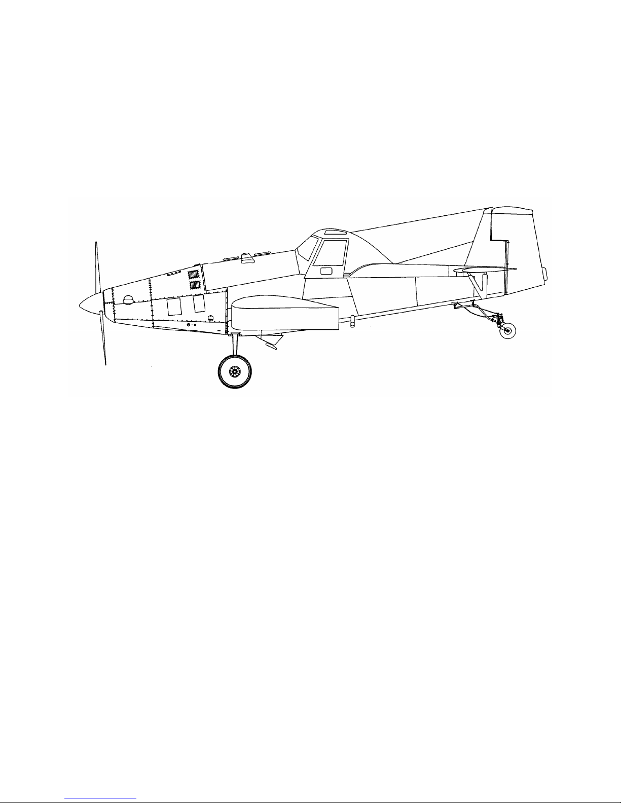
Figure 1-1: Aircraft 3-view...............................................................................8
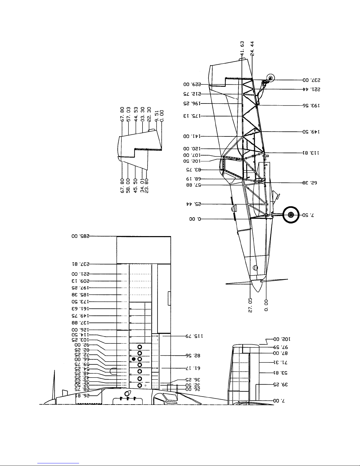
Figure 1-2: Aircraft Stations.............................................................................
9
Effective: 9/16/05 1-1

THRUSH AIRCRAFT, INC – MODEL S2RHG-T65 TURBO THRUSH
AIRCRAFT MAINTENANCE MANUAL
GENERAL DESCRIPTION
The Thrush Aircraft Inc Turbo Thrush is designed especially for agricultural flying. It is a
monoplane featuring a full cantilever low wing and all metal construction. The design and
construction of the airframe components assure all structural integrity, flight safety, and
minimum maintenance requirements. The Turbo Thrush is designed for the highest crash
load factors in the industry. Safety and reliability of operation and maximum pilot crash
protection are proven and effective features of the design. The high strength overturn
structure is a proven design. The fuselage and overturn structure, constructed throughout
of chrome-moly steel tubing, is immensely strong in the cockpit area.
CONTACT INFORMATION
For further information related to this manual, please contact our Product Support
Manager at(229) 883-1440 extension 524.
PRINCIPAL DIMENSIONS
GENERAL
Wing Span Extended Tip 47.5 feet
Overall Length 33.33 feet
Height To Top Of Canopy 10.0 feet
Main Gear Tread 9.35 feet
Main Gear To Tail Wheel 19.71 feet
WING
Type Full Cantilever
Airfoil Section NACA 4412
Dihedral 3.50 Degrees
C. G. Range (See Airplane Flight Manual for pertinent data)
Forward Limit at 7600 pounds and below is
22.5 inches aft of datum.
Forward Limit
Aft Limit
Forward Limit at 10500 pounds is 26 inches
aft of datum with straight line variations to
7600 pounds at 22.5 inches.
29.0 Inches Aft Of Datum
28.0 inches for dual cockpit
Datum Datum Is The Leading Edge Of The Wing.
Aileron Travel
-Up 21 Degrees ±1 Degree
-Down 17 Degrees ±1 Degree
Flap Travel Down 15 Degrees ±1 Degree
1-2 Effective: 9/16/05

THRUSH AIRCRAFT, INC – MODEL S2RHG-T65 TURBO THRUSH
AIRCRAFT MAINTENANCE MANUAL
HORIZONTAL STABILIZER AND ELEVATORS
Span 204 Inches (17')
Elevator Travel
-Up 27 Degrees ±1 Degree
-Down 17 Degrees ±1 Degree
Trim Tab Travel
-Up 8 Degrees ±1 Degree
-Down 22 Degrees ±1 Degree
VERTICAL STABILIZER AND RUDDER
Rudder Travel 22 Degrees ±1 Degree
AREAS
Wing 362.9 Square Feet
Aileron (Each) 23.40 Square Feet
Flaps (Each) 15.30 Square Feet
Stabilizer 39.30 Square Feet
Elevators 20.40 Square Feet
Elevator Tabs (Each) 1.30 Square Feet
Fin with Dorsal 13.78 Square Feet
Rudder 11.40 Square Feet
SUPPLIER FURNISHED COMPONENT MANUALS
COMPONENT MANUAL PART #
PT6A-60AG
Parts Manual 3034344
PT6A-65AG, PT6A-65AR,
PT6A-65B
Maintenance Manual
Vol. I & II
Maintenance Manual
Vol. I & II
3034342
3032843
Parts Manual 3032844
PT6A-45A, PT6A-45B,
PT6A-45R
Parts Manual 3027044
Propeller Owner’s Manual 139
Effective: 9/16/05 1-3
Maintenance Manual
Vol. I & II
3027042

THRUSH AIRCRAFT, INC – MODEL S2RHG-T65 TURBO THRUSH
AIRCRAFT MAINTENANCE MANUAL
AIRCRAFT STRUCTURE
FUSELAGE
The fuselage is comprised of a welded tubular steel frame, fiberglass hopper, and
detachable skins. An overturn structure forms an integral part of t he fuselage fr ame. T h e
frame structure, fittings, bushings, brackets, and so forth are fabricated from 4130
chrome-moly seamless steel tubing.
As a corrosion preventative, hot linseed oil is pumped throughout the entire welded
structure. On an average, 12 gallons are pumped into the frame and 11 to 11 ½ gallons
drain out, leaving a residual coating on all members. The exterior of the frame is
sandblasted, etched, and primed, which is followed by two coats of polyurethane paint
that is resistant to chemical reaction.
The fuselage is covered with heat treated Alclad panels attached with camloc fasteners.
Side skins can be removed using only a screwdriver, thus exposing the fuselage frame
for thorough cleaning and inspection. All skins are supported clear of the fuselage tubing
to prevent accumulation of corrosive chemicals. The seams and lap joints of the skin
panel support structure are sealed with a special compound to eliminate chemical action
between the mating surfaces. Each skin panel is etched, primed, and painted before
assembly to insure complete coverage. All bottom fuselage skins around the hopper
opening and aft to the tail post are made of stainless steel. The skin fasteners in the high
corrosion areas are also stainless steel.
WING
The wing has a constant chord of 90 inches, and is all metal, full cantilever design. The
massive main spar is a tension field beam structure constructed from Alclad webs and
high strength heat-treated steel caps. All wing skins, ribs, and leading edges are
constructed from Alclad heat-treated material. The leading edge structure is made
especially strong to minimize denting and is riveted with universal rivets for strength. The
fuel tanks, which are located in the inboard section of the wing, are an int egral part of t he
structure. Close pitch riveting of the seams, substantial reinforcement, and flexible
sealants minimize chances of rupture in crash conditions. Drain holes are provided in
adjacent bays to prevent accumulation of fuel in the event of a leak. The ailerons and
flaps are all metal construction and are hinged on ball bearings. The flaps are electric ally
operated by push rods and are completely sealed against chemical entry. Flap hinges
are stainless steel.
EMPENNAGE
The horizontal stabilizer, elevator, rudder and vertical fin are an all-metal structure. All
skins, ribs and leading edges are constructed from alclad material. The movable surfaces
are hinged on sealed bearings that can be easily replaced. The rudder and the elevator
have aerodynamic balances that are protected by overhangs on the fixed surfaces.
1-4 Effective: 05/05/04

THRUSH AIRCRAFT, INC – MODEL S2RHG-T65 TURBO THRUSH
AIRCRAFT MAINTENANCE MANUAL
COCKPIT
There are two choices of the enclosed cockpit canopies for the Turbo Thrush (1) the
SINGLE cockpit canopy or (2) the DUAL cockpit canopy. The overturn structure of both
is exceptionally strong and welded to "hard points" in the fuselage frame. The forwar d
bracing supports the windshield support channels and is welded to a lateral tube that is
curved to provide more head clearance. The fiberglass canopy sh ell has extra thickness
on the top portion and is well attached to the extra large steel tube structure so that it will
serve as a skid in case of overturn. The large canopy doors permit easy entrance to one
or both cockpits. The doors should not be removed for flight, as the aircraft performance
will be lowered. The cockpit seat belts are anchored to the seat structure, and the
shoulder harnesses are secured to a steel channel at the bottom of the seat structure.
The seats adjust vertically. The rudder pedals adjust fore and aft. The windshield is a
three-piece construction. The center section is tempered safety plate glass for better
resistance to scratching and is enclosed in a stainless steel frame. The windshield side
panels are Plexiglas and are curved to provide streamlining.
AIRCRAFT SYSTEMS
HYDRAULIC SYSTEMS
The hydraulic system consists of two master brake cylinders with hydraulic lines
connecting the master cylinders to the wheel brake cylinders. Applying toe pressure on
the rudder pedals actuates the master cylinders, which are locat ed just aft of the pilot’s
rudder pedals. A small reservoir is incorporated within each master cylinder to supply the
system with brake fluid.
POWER PLANT & PROPELLER
The Turbo Thrush is powered by the PT6, a lightweight free turbine engine incorporating
a reverse flow combustion path, designed for aircraft propulsion use. It utilizes two
counter rotating turbine sections. One drives the compressor, and the other drives the
propeller through a reduction gearbox. The latter turbine is "free" or independent of the
compressor turbine. More recent and higher-powered models incorporate a two-stage
free turbine. The PT6 has been produced in several models and has been adapted to a
multitude of uses.
The propeller has five blades mounted on a hollow hub, in the front end of which is a
servo-piston that moves forward under servo-oil pressure or rearward under feather
return spring pressure, assisted by counterweight s. There are five links from the servopiston, one going to each blade root. These links transmit forward motion of the servopiston to the blade roots and pivot the blades in the decrease pitch direction. When
servo-piston pressure is relieved, the servo-piston moves rearward under feather return
spring pressure and pivots the blades in the increase pitch direction. This action is
assisted by centrifugal force of the counterweight on each blade root.
A 230-gallon fuel supply is available for the Turbo Thrush. In each wing, fuel is containe d
inside integral wing tanks (wet wing fuel tanks) just outboard of the wing walks. The left
wing and right wing fuel tanks are interconnected through a 5 U.S. gallon header tank that
is located in the fuselage. The fuel supply lines, to the engine, are routed from the header
tank outlet finger screen through a fuel shutoff (on/off) valve to an electric driven fuel
Effective: 9/16/05 1-5
FUEL SYSTEM

THRUSH AIRCRAFT, INC – MODEL S2RHG-T65 TURBO THRUSH
AIRCRAFT MAINTENANCE MANUAL
boost pump.
The electrically driven fuel boost pump serves two purposes, first as a backup system to
provide continuous fuel pressure to the engine high pressure fuel pump in case the
engine driven fuel boost pump fails and secondly to provide boosted fuel pressure to the
engine high pressure fuel pump during engine starting. The electric driven fuel boost
pump discharge is then routed through a 25-micron main fuel filter to an engine driven
fuel boost pump.
The aircraft’s fuel system is equipped with two fuel filters, a ¼ inch mesh finger strainer is
installed in the outlet fitting from the header tank and a 25-micron, airframe supplied, main
fuel filter located on the forward L/H side of the firewall. Fuel from the air craft fuel system
enters the engines high pressure fuel pump which has two fuel filters of its own, an 74micron inlet filter and a 10-micron discharge filter (refer to the engine appropriate
maintenance manual for pertinent maintenance details for the engine supplied filt ers and
fuel system).
The fuel tank vent system is designed to keep the fuel spillage to a minimum. The fuel
tanks are vented through tubing connected at both the inboard and outboard ends of the
individual fuel tanks to the centrally located vent system in the fuselage. Ram air enters a
vent scoop, on the fuselage, under the left wing and pressurizes the vent system to
maintain positive pressure on the fuel tanks. The vent system is provided with two quick
drains, located on the fuselage under each wing, to drain any fuel that might happened to
have got in the tanks outboard vent lines.
At engine shutdown, fuel from the start control unit or the flow divider/dump valve, located
at the 6 o’clock position on the engine fuel nozzle manifold, is directed to a residue fuel
reservoir “EPA tank” mounted inboard on the L/H aft shin skin. This reservoir holds
approximately 3 engine shutdowns worth of fuel before t he fuel will exit the reservoir vent
system. (NOTE: This reservoir should be emptied after each engine shutdown.) (NOTE:
It is common and normal after an engine compressor Water Wash or Performance
Recovery Wash to have water or soap appear in the reservoir’s drained waste fuel.)
The fuel quantity gauge is located on the lower left instrument panel. The fuel quantity
indicating system consists of two transmitters, one indicator gauge, and an L/H or R/H
tank fuel quantity selector switch. A transmitter installe d in each wing tank transmits an
electrical signal to the single fuel quantity indicator. The instrument reads both the left
and right fuel tanks singularly as chosen by the electrical control switch, adjacent to the
fuel quantity indicator gauge on the instrument panel.
The two fuel tanks are serviced through filler ports located on the top of both wings. The
filler ports incorporate security chains to prevent the loss of the fuel caps. Service the
aircraft from refueling facilities that utilize proper ground handling equipment and filter
systems to remove impurities and water accumulation from the bulk fuel. If filtering
facilities are not available, filter the fuel through a quality high-grade chamois. Fuel tanks
should be serviced after the last flight of each day to reduce condensation and allow any
entrapped water accumulations to settle to the fuel system drains, to be removed, prior to
the next flight.
Prior to the first flight of the day the header tank and fuel filter should be drained to check
for the presence of water or sediment in the fuel system. If there is a possibility, at any
time, that any tank may contains water, the header tank and fuel filter should be drained
as necessary to ensure no water exists in the fuel system. For fuel system servicing
1-6 Effective: 05/05/04

THRUSH AIRCRAFT, INC – MODEL S2RHG-T65 TURBO THRUSH
AIRCRAFT MAINTENANCE MANUAL
information, refer to Section 2.
LANDING GEAR, WHEELS & BRAKES
The main landing gear is made using a formed chrome-moly spring steel unit. The left
main gear and the right main gear are symmetrical. The main wheels are 29 x 11. The
spring steel construction and design of the main gear allow for absorption of landing
weight and common stresses associated with such, thus eliminating the need for shock
struts. The brake system has individual toe brakes and individual park brakes. The use of
a special N-513 compound cup in each master cylinder permits the use of MIL-H-5606, a
heavy-duty aviation hydraulic fluid. The brak es are dual caliper disc types. The tail gear
is a spring steel type and uses a 6.00 x 6 tailwheel.
FLIGHT CONTROLS
The flight controls are of conventional design employing extensive use of ball b ear ings for
low friction and smoothness of operation. The aileron and elevator controls are push rod
systems and the rudder control is through cables. The elevator trim control is actuated by
a lever that moves the tab to the desired position through push rods. The wing flaps are
operated electrically and controlled by a switch located on the left side of the cockpit. The
rudder controls are interconnected by springs to the aileron system so that a wing m ay be
lifted with the rudder alone.
INSTRUMENTS
The standard instruments are located on three separate panels: An upper panel, a left
panel, and a right panel. The left panel contains a clock, oil temperature, hour meter, fuel
pressure, oil pressure, air filter Delta “P”, and fuel quantity gauges. The right panel
contains a voltmeter, ammeter, and circuit breakers. The upper panel contains all enginewarning lights, torque pressure, ITT indicator, Gas Generator percent RPM, Propeller
RPM and standard flight instrument package.
ELECTRICAL SYSTEM
The standard 24 volts and 105 amp electrical system consists of the starting system, the
navigation lights, the wiper/washer system, and the strobe lights. The landing lights, the
working lights, and the air conditioner system are optional. The landing and working
lights may be installed in the field, since the wiring for them is included in the standard
wire bundle. The electrical system obtains power from two 24-volt batteries and one
starter/generator. An external power receptacle is standard equipment and may be used
for connecting a 24-volt ground power unit to the aircraft for engine starting or
maintenance. The ground start system utilizes the master relay so that starting is
accomplished by engaging the starter switch.
AIRCRAFT WEIGHT & BALANCE
Refer to S2RHG-T65 Flight Manual for aircraft weight and balance information.
Effective: 9/16/05 1-7

THRUSH AIRCRAFT, INC – MODEL S2RHG-T65 TURBO THRUSH
AIRCRAFT MAINTENANCE MANUAL
1-8 Effective: 05/05/04
Figure 1-1: Aircraft 3-view
THRUSH AIRCRAFT, INC – MODEL S2RHG-T65 TURBO THRUSH
AIRCRAFT MAINTENANCE MANUAL
Effective: 05/05/04 1-9
Figure 1-2: Aircraft Stations

THRUSH AIRCRAFT, INC – MODEL S2RHG-T65 TURBO THRUSH
AIRCRAFT MAINTENANCE MANUAL
SECTION 2
SERVICING & INSPECTION
TABLE OF CONTENTS
SERVICING & INSPECTION..........................................................................................
3
GROUND HANDLING .................................................................................................... 3
TOWING....................................................................................................................3
TAXIING .................................................................................................................... 3
PARKING................................................................................................................... 3
MOORING................................................................................................................. 3
JACKING...................................................................................................................4
LEVELING .................................................................................................................4
COLD WEATHER OPERATION.....................................................................................
COLD WEATHER MAINTENANCE HINTS ...............................................................
4
4
GROUND EMERGENCY PROCEDURES......................................................................5
ENGINE FIRES..........................................................................................................5
ELECTRICAL FIRES................................................................................................. 5
GROUND OPERATION OF ENGINE ............................................................................. 6
BEFORE STARTING ENGINE ..................................................................................6
STARTING ENGINE.................................................................................................. 6
ENGINE OPERATIONAL CHECK............................................................................. 7
SYSTEM AND COMPONENT SERVICING.................................................................... 8
HYDRAULIC SYSTEM .............................................................................................. 8
ENGINE OIL SYSTEM...............................................................................................8
FUEL SYSTEM........................................................................................................ 11
DEFUELING ............................................................................................................13
INDUCTION SYSTEM............................................................................................. 14
LANDING GEAR, WHEELS & BRAKES......................................................................
TIRES...................................................................................................................... 14
BRAKE BLEEDING.................................................................................................. 14
INSPECTION ................................................................................................................14
INSPECTION CHECK LIST.....................................................................................
INSPECTION CHART...................................................................................................16
PROPELLER ...........................................................................................................
ENGINE EXTERNALS.............................................................................................17
ENGINE OIL SYSTEM.............................................................................................
OIL COOLER AUGMENTATION (GROUND).......................................................... 19
ENGINE FUEL SYSTEM.........................................................................................
IGNITION SYSTEM.................................................................................................
PNEUMATIC SYSTEM............................................................................................
AIRFRAME FUEL SYSTEM ....................................................................................
MAIN LANDING GEAR............................................................................................21
TAIL GEAR..............................................................................................................
Effective: 09/16/05 2-1
14
15
16
18
19
20
21
21
22

THRUSH AIRCRAFT, INC – MODEL S2RHG-T65 TURBO THRUSH
AIRCRAFT MAINTENANCE MANUAL
FUSELAGE SKINS..................................................................................................
HOPPER..................................................................................................................
WINGS.....................................................................................................................24
FUSELAGE FRAME................................................................................................ 25
CONTROL SYSTEMS............................................................................................. 26
METAL EMPENNAGE.............................................................................................
AILERONS AND FLAPS..........................................................................................
COCKPIT.................................................................................................................28
ELECTRICAL SYSTEM...........................................................................................29
CORROSION CONTROL ............................................................................................. 29
WINDSHIELD ..........................................................................................................30
HOPPER REPAIR ...................................................................................................30
FUEL TANK REPAIR...............................................................................................30
BATTERY MAINTENANCE..................................................................................... 30
Figure 2-1: Tie Down and Jack Points...............................................................32
Figure 2-2: Wing Fuel Fillers and Drains...........................................................
Figure 2-3: Fuselage Fuel Drains......................................................................
Figure 2-4: Fuel Filter Location..........................................................................35
Figure 2-6: Lubrication Chart.............................................................................. 36
Figure 2-7: Torque Chart....................................................................................44
Figure 2-8: Engine Oil Servicing......................................................................... 45
24
24
27
27
33
34
2-2 Effective 9/16/05

THRUSH AIRCRAFT, INC – MODEL S2RHG-T65 TURBO THRUSH
AIRCRAFT MAINTENANCE MANUAL
SERVICING & INSPECTION
Standard procedure for ground handling, servicing, inspection, airframe maintenance,
lubrication, and storage are included in this Section. Adherence to these proced ures on a
scheduled basis can save many hours of maintenance and aircraft down time. When a
system component requires service or maintenance other than that outlined in this
Section, refer to the applicable Section of this manual for complete information.
GROUND HANDLING
TOWING
Movement of the aircraft on the ground may be accomplished as follows:
A. Pull and guide the aircraft by means of a tow bar with the tail wheel unlocked.
B. Attach a rope harness to the main gear when there is a need to tow the aircraft
forward through snow or over soft and/or muddy ground.
TAXIING
Before attempting to taxi the aircraft, maintenance personnel should be checked out by
qualified personnel. When it is determined that the propeller area is clear, apply the
power to start the taxi roll and perform the following:
A. Push the stick full forward to unlock the tail wheel.
B. Taxi a few feet and check the brake operation.
C. While taxiing, make slight turns to determine that the tail wheel steering is
operative.
D. Avoid taxiing over ground of loose stones, gravel, or other loose material that
may cause foreign object damage to the propeller or to other aircraft in the area.
E. You may taxi with the power lever in the Beta region to govern ground speed.
Observe all engine operating limits.
PARKING
Head the aircraft into the wind and set the parking brake. Do not set the parking brake
during cold wet weather because the accumulated moisture may freeze in the brakes. Do
not set the parking brake if the brakes are overheated. Install t he internal control lock.
Place the chocks under each main wheel.
MOORING
Park aircraft as previously outlined. In winds up to 20 knots, secure the aircraft at the
wing tie down rings. For winds above 20 knots, tie the tail and main gear as well as the
wings. Install external control surface locks. Be sure to tie t he propeller down to prev ent
it from wind milling with zero oil pressure. The aircraft should be placed in a hangar when
wind velocity is predicted to exceed 50 knots. When mooring aircraft, use 3/4-inch ma nila
or nylon rope. A clove hitch or other anti-slip knot should be employed. If a manila rope
is used for tie down, allow enough slack to compensate for contraction of the rope fiber
without damaging the aircraft.
Effective: 05/05/04 2-3

THRUSH AIRCRAFT, INC – MODEL S2RHG-T65 TURBO THRUSH
AIRCRAFT MAINTENANCE MANUAL
JACKING
Jack points are provided on each main spar and located at wing s tations 120 & 193.38.
When using the jack points to lift the aircraft, all hopper loads should be removed. (Fig. 2-
1) A jack point is also provided on the tail wheel trunnion attach fitting on the lower left
longeron.
LEVELING
The aircraft may be leveled by raising the tail to an approximate level flight position and
by supporting the tail on a stable jack or platform. Adjust the height of the tail wheel until
the left-hand lower longeron located under the cockpit is level.
COLD WEATHER OPERATION
Aircraft operation in cold weather creates a need for additional maintenance practices and
operating procedures that are not required in moderate temperatures. Whenever
possible, shelter the aircraft in a heated hangar to prevent frost, ice, or snow
accumulation that requires added maintenance time to remove. These weather
elements, if allowed to accumulate only a fraction of an inch in thickness on the crit ical
airfoils and control surfaces, seriously degrade aircraft lift and flight control effectiveness.
The possibility of aircraft system failures is increased when the aircraft is parked where
wind driven snow or freezing rain can be forced into various openings of the aircraft. If
the aircraft is to be moored outside in extreme cold, the battery should be kept fully
charged to prevent freezing. Make certain that all vents, air inlets, and so forth are
covered.
Locating the aircraft inside a heated hanger is the most effective method of preheating the
aircraft. The use of an external power unit is recommended to conserve the battery.
COLD WEATHER MAINTENANCE HINTS
The information that follows is intended only for the purpose of supplementing the existing
information in this manual when operating the aircraft in cold weather. Keeping the
aircraft in top maintenance condition during cold weather cannot be over stressed.
The battery should be maintained at full charge during cold weather to prevent freezing.
After adding water to the battery in freezing temperatures, charge the battery to mix t he
water and electrolyte. A frozen battery may explode when subjected to a high charge
rate. Corrosive damage to the area adjacent to an exploded battery will result if the
electrolyte solution is not removed immediately. Instructions for removing spilled
electrolyte are provided in this Section. The battery should be removed and stored in a
warm place if the aircraft is to remain idle for an extended period of time.
In the fuel system, condensation is more likely to occur in cold weather due to a more
rapid and positive division of moisture content from other fuel properties. If at all possible,
use fueling facilities that filter moisture from the fuel. If fueling facilities with filters are not
available, filter the fuel through a good quality chamois. Fill the tanks with correct grade
of fuel as soon as possible after landing to reduce the possibility of condensation and ice
formation in the tanks. Fuel extracted from fuel header tank drain before starting
deserves a closer examination when the aircraft is being operated in cold weather.
Cold weather operation demands procedures that are in addition to normal Post Flight
2-4 Effective 05/05/04

THRUSH AIRCRAFT, INC – MODEL S2RHG-T65 TURBO THRUSH
AIRCRAFT MAINTENANCE MANUAL
Maintenance Procedures. Fill the fuel tanks immediately after flight. If shelter is not
available, tie the aircraft down and install covers on all vents, openings, etc. as required.
GROUND EMERGENCY PROCEDURES
Emergency procedures must be accomplished as rapidly as possible, should an
emergency arise. It is suggested that steps pertaining to each emergency be committed
to memory in order to accelerate the procedure and minimize any possible damage.
ENGINE FIRES
The following Dry Motoring Run procedure is used to clear an engine at any time when
deemed necessary to remove internally trapped fuel and vapor or when there is evidence
of a fire within the engine. Air that passes through the engine serves to pur ge fuel, vapor,
or fire from the combustion sections, the gas generator turbine, the power turbine, and the
exhaust system.
A. Fuel Condition Lever - Cut Off
B. Ignition Switch - Off
C. Master Switch - On
D. Fuel Shutoff Valve - On
E. Fuel Auxiliary Pump Switch - On
F. This will provide lubrication for the engine-driven fuel pump.
G. Engine Starter Switch – On
*** WARNING ***
If the fire persists, as indicated by sustained
high inter-turbine temperature, close the fuel
system shutoff valve and continue motoring.
F. Maintain the starter operation for the desired duration. The maximum starter
duration is 3 minutes.
G. Engine Starter Switch - Off
H. Fuel Auxiliary Pump Switch - Off
I. Fuel Shutoff Valve - Off
J. Master Switch - Off
K. Allow a 5-minute cooling period for t he starter before going any further with the
starting operation.
Circuit breakers will automatically trip and stop the current flow to a shorted circuit.
However, as a safety precaution in the event of an electrical fire, turn the battery switches
to off. Use a fire extinguisher approved for electrical fires to extinguish the flame.
Effective: 05/05/04 2-5
ELECTRICAL FIRES

THRUSH AIRCRAFT, INC – MODEL S2RHG-T65 TURBO THRUSH
AIRCRAFT MAINTENANCE MANUAL
GROUND OPERATION OF ENGINE
BEFORE STARTING ENGINE
Visually check the aircraft for general condition. Verify that all Camlocs on the skin
panels are fastened. Remove all accumulations of frost, ice, or snow in cold weather
from the wing, the tail, and the control surfaces. Check that the control surfaces conta in
no internal accumulations of ice. Remove the inlet and exhaust covers, if fitted. If night
flight is planned, check the operation of all lights and have a flashlight available.
After a complete visual inspection has been accomplished, the following checklist may be
used for the external prestart check. The aircraft should be headed into the wind and
should have the wheel chocks in place.
A. A fire extinguisher must be readily available in the event of an engine fire.
B. Check the engine oil level. Assure that the oil system has been serviced with the
correct grade of oil.
C. Verify that the internal control lock has been removed and that the controls
operate freely.
D. Set the parking brake.
E. Check the fuel quantity in both tanks.
F. Set the trim tabs for takeoff.
G. Clear the area of all personnel.
STARTING ENGINE
Use the following procedure to start the PT6A engine.
A. Battery and Generator Switches - On
B. Power Lever - Idle
C. Propeller Lever – Feather
D. Fuel Condition Lever - Cut Off
E. Fuel Shutoff Valve – On
F. Fuel Auxiliary Pump Switch - On
G. Fuel Inlet Pressure Indicator - Check 5 PSIG Minimum
H. Engine Starter Switch – On. The minimum speed to obtain a satisfactory light is
13% Ng.
I. After approximately 5 seconds of motoring at the stabilized gas generator speed,
turn the Ignition Switch On and move the Condition Lever to the Ground (low)
idle position.
J. Observe that the engine accelerates normally to idle RPM and the maximum
allowable inter-turbine temperature-starting limit is not exceeded.
** CAUTION **
2-6 Effective 05/05/04

THRUSH AIRCRAFT, INC – MODEL S2RHG-T65 TURBO THRUSH
AIRCRAFT MAINTENANCE MANUAL
Whenever the gas generator fails to light off within 10
seconds after moving the fuel condition lever to the ground
(low) idle position: pull fuel condition lever to idle cutoff and
turn ignition and starter switches off. Allow a 30-second fuel
draining period that is followed by a 15-second dry motoring
run before attempting another start. If for any reason a
starting attempt is discontinued, allow the engine to come to a
complete stop and then accomplish a Dry Motoring Run as
described above under Engine Fires.
When the engine attains idle rpm:
K. Engine Starter Switch and Ignition Switch - Off
L. Oil Pressure - Check 60 PSIG Minimum
M. Fuel Auxiliary Pump - Off
N. Fuel Pressure from Engine Driven Pump - Check 5 PSI Minimum
O. Generator Charging – Check
ENGINE OPERATIONAL CHECK
** CAUTION **
Fill hopper and hold the elevator control firmly
full up during all high power ground operations
to keep aircraft from nosing over.
Refer to Section Four and/or Pratt & Whitney Maintenance Manual for specific operational
checks.
Before proceeding with a ground run up, be sure that the propeller system is purged by
feathering the propeller once or twice with the power control lever in idle position.
The following procedure should be used to check the propeller over speed governor.
A. Place the propeller lever in full increase RPM position (forward).
B. Turn prop test switch on.
C. Increase RPM with the power lever until governing occurs. This should occur at
1598 ±20 RPM. (In no case should any engine limitations be exceeded.)
D. Reduce power back to idle.
E. Turn prop test switch off.
*NOTE*
If RPM is not governed at 1598 ±20 RPM with
the prop test switch on, consult Section IV of
this manual for adjustment of the overspeed
governor.
Effective: 05/05/04 2-7

THRUSH AIRCRAFT, INC – MODEL S2RHG-T65 TURBO THRUSH
AIRCRAFT MAINTENANCE MANUAL
SYSTEM AND COMPONENT SERVICING
Servicing procedures contained in this Section are confined t o thos e maint enance act ions
that occur with routine frequency and require a reasonably short period of time to
accomplish. Servicing practices and maintenance to aircraft systems and components
that require less frequent attention are contained in the appropriate Section of this
manual.
HYDRAULIC SYSTEM
The hydraulic system consists of two master brake cylinders and the n ecessary hydra ulic
lines connecting the master cylinders to the wheel brake cylinders. Applying toe pressure
on the rudder pedals actuates the master cylinders, which are located just aft of the pilot’s
rudder pedals. Refer to Section Six for brake servicing procedures.
ENGINE OIL SYSTEM
Ref. Figure 2-8
The oils that are specified for the lubrication system are detailed in the Pratt and Whitney
Canada Service Bulletin 13001. All oils listed in the bulletin are approved for flight
operation. It is recommended for all turbo aircraft that the oil should be changed every
400 hours. The oil system contains 13 U.S. quarts.
In cases where oils that are approved are not available, an operator must obtain prior
approval or recommendations for use of substitution oil from the Service Department,
Pratt and Whitney Canada Corp, 1000 Marie-Victorin, Longueuil, Quebec, Canada J4K
1A1. Phone: 1-800-268-8000 (U.S. & Canada) or 450-647-8000 (International).
A. OIL LEVEL CHECK
1. To avoid overfilling of oil tank, and high oil consumption, an oil level check
is recommended within 30 minutes after shutdown. Ideal interval is 15 to 20
minutes. If more than 30 minutes has passed, and the dipstick indicates
that oil is needed, start the engine and run at ground idle (low idle) for five
minutes, and recheck oil level.
** CAUTION **
Do not mix different brands, viscosity’s, or types
of oil since their chemical structures may make
them incompatible. If different types of oil
become mixed, drain and flush the system.
Refill with new oil.
2. Unlock the filler cap and dipstick from the filler neck at the eleven o'clock
position on the accessory gearbox and remove the filler cap.
3. Check the oil tank contents against the markings on t he dipstick. Service
as required.
* NOTE *
The graduations on the dipstick indicate the oil level in U.S.
quarts below maximum capacity of the oil tank. The normal
2-8 Effective 9/16/05

THRUSH AIRCRAFT, INC – MODEL S2RHG-T65 TURBO THRUSH
AIRCRAFT MAINTENANCE MANUAL
cold oil level is the Maximum Cold mark on the dipst ick. The
normal hot level is Maximum Hot mark on the dipstick. A
dipstick reading of 3 will indicate that the system requires 2
U.S. quarts to replenish to normal level if the oil is cold. If the
oil is hot, it will take 3 U.S. quarts to replenish.
4. If the engine is nose high or nose low, compensation must be made to
avoid over or under servicing.
B. If the oil level is too low to register on the dipstick due to possible excessive
consumption or if low or fluctuating pressures have been recorded, refer to
Troubleshooting - Lubrication Problems in the Pratt and Whitney Maintenance
Manual for the action to be taken. After that has been accomplished, proceed as
follows to check the oil level.
1. Fill the oil tank to the appropriate normal le vel. Record the quantity of oil
added to the system.
2. Install the filler cap and dipstick. Ensure that the cap is locked securely.
3. Run the engine idle for approximately 5 minutes.
4. Check the oil level.
5. Check the oil filter per applicable Pratt & Whitney Maintenance Manual.
C. On engines which have remained stationary for a period of 12 hours or more,
proceed as follows to check the oil level.
1. Start the engine and run at idle speed for a minimum of 2 minu tes .
2. Feather the propeller.
3. Shut down the engine.
4. Check the oil level.
D. Recommendations for oil change intervals are based on the performance of
specific brands of oil, specific types of oil, specific engine models, and specific
operating criteria. General oil change intervals may be extended periodically and
will be reflected by revisions to the Pratt and Whitney Engine Service Bulletin
13001. Permission for extension of oil drain intervals may be granted to
operators through monitoring programs, which are conducted by most major oil
companies that have been approved by Pratt and Whitney Canada. Service
Bulletin 13001 will be revised periodically to include newly approved oils. Refer
to Figure 2-8 for the locations called out in the following procedure.
1. Place suitable containers or drip pan under the engine.
2. Remove lock wire from the main oil tank’s drain plug (Figure 2-8, #6) from
boss on compressor inlet case. Remove drain plug. Discard the preformed
packing. Also drain oil at drain port on left shin skin (on aircraft equipped
with quick drain).
3. Remove the rear case drain plug (Figure 2-8, #2) from the six o'clock
position on the rear face of the accessory gearbox housing. Discard the
preformed packing.
Effective: 05/05/04 2-9

THRUSH AIRCRAFT, INC – MODEL S2RHG-T65 TURBO THRUSH
AIRCRAFT MAINTENANCE MANUAL
4. Remove the chip detector (F igure 2-8, #3) from the six o'clock position on
the reduction gearbox front case. Discard the preformed packing.
5. Visually examine the drained oil for the presence of foreign matter.
E. Refill the oil tank by accomplishing the following procedures.
1. Install the chip detector with new preformed packing on the reduction
gearbox. Torque chip detector body 45 to 55 lb. in. and lock wire.
2. Install rear case drain plug with new preformed packing in the accessory
gearbox housing. Tighten and torque to 215 to 240 lb. in. and lock wire.
3. Install the drain plug with the new preformed packing in the bottom of the air
inlet case and lock wire. Install a cap on the drain port on the left shin skin
(on aircraft equipped with quick drain) and lock wire.
4. Fill the oil tank with t he specified oil to the level of maximum graduation on
the dipstick.
F. Install the filler cap and dipstick assembly in the oil tank. Ensure that the cap is
locked securely.
1. Start the engine and run at idle for approximately 2 minutes to circulat e the
oil through the system.
2. Feather the propeller.
3. Shut down the engine.
4. Check the oil level in the tank. Replenish, as required, to the normal level
on the dipstick.
5. Install the filler cap and dipstick asse mbly in the oil tank. Ensure that the
cap is locked securely.
G. If an engine is to be operated with an oil brand or type that differs from that on
which it previously operated or if the oil system has been contaminated by other
than metallic matter, the oil system should be flushed by following the steps
below:
1. Place suitable containers or drip pan under the engine.
2. Remove the oil drain plug or chip detector from the reduction gearbox an d
the plugs from the inlet case and the accessory gearbox housing.
** CAUTION **
Limit the engine rotation to the minimum which
is required to accomplish the complete draining.
Also observe the starter operating limitations.
3. With the drains open, place the starting control lever to cutoff and the
ignition switch to off. Motor the engine with the starter only to allow the
scavenge pumps to clear all lubricating oil.
4. Reinstall all drain plugs and the chip detector.
5. Refill the engine oil tank with new type oil .
2-10 Effective 05/05/04

THRUSH AIRCRAFT, INC – MODEL S2RHG-T65 TURBO THRUSH
AIRCRAFT MAINTENANCE MANUAL
6. Start engine and run at idle speed for a minimum of two minutes.
7. Feather the propeller.
8. Shut down the engine.
9. Repeat Steps 1. through 3.
10. Remove the main oil filter. Clean or replace the filter and reinstall.
11. Remove the reduction gearbox oil strainer and clean. Reinstall the strainer.
12. Reinstall all engine drain plugs and the chip detector. Tighten, torque, and
lock wire.
13. Repeat Steps 5. through 8.
14. Check the oil levels and replenish, as necessary.
15. Install the filler cap and dipstick assembly in the f iller tube. Ensure that the
cap is correctly installed and locked.
** CAUTION **
Different formulations of the various oil brands may have
varying detergent actions. After an oil brand change, the
above may cause the release of carbon particles into the oil
system which would result in the clogging of the scavenge
screen. After a change of oil brand, the main oil filter should
be inspected for carbon particles at 10-hour int ervals. There
should be 5 inspections for a total of 50 hours, and the filter
should be checked at the routine oil filter checks thereafter up
to 500 hours. If an excess of the amount of carbon is noted,
the following steps should be accomplished.
a. Remove the drain plug from the six o'clock position on the accessory
gearbox.
b. Using a mirror and light, inspect the scavenge screen through the
drain hole.
c. If there is evidence of carbon, try to dislodge it with a stiff pai n tbr us h.
d. Flush out any removed carbon.
e. If the carbon cannot be removed by the above method, the
accessory gearbox should be removed and the screen cleaned.
Refer to the Accessory Gearbox Section in the Pratt and Whitney
Maintenance Manual for the removal procedure.
A. Refuel the aircraft with fueling facilities that contain filters for removing the
moisture content from the fuel. If the fueling facilities with filters are not available,
filter the fuel through a good grade of chamois. The fuel tanks should be
serviced after the last flight of the day to allow maximum time for the moisture to
reach the header tank. Service the aircraft with Jet A, Jet B, JP-4, or JP-5. If jet
fuel is not available, aviation gasoline MIL-G-5572 (all grades) may be used for a
Effective: 05/05/04 2-11
FUEL SYSTEM

THRUSH AIRCRAFT, INC – MODEL S2RHG-T65 TURBO THRUSH
AIRCRAFT MAINTENANCE MANUAL
maximum of 150 hours between overhauls. For the Restricted Category, service
the aircraft with Jet A, Jet B, JP-4, JP-5, or automotive diesel number 1D or 2D in
accordance with P&WC Specifications CPW204, CPW 46 and CPW 381.
Automotive diesel fuel is approved only for flights when the free air temperature
is above +20 degrees Fahrenheit use grade #1D or +40 degrees Fahrenheit use
grade #2D.
*** WARNING ***
Ground the aircraft and the fuel servicing
equipment to the aircraft. Smoking in or around
the aircraft during refueling operations is
prohibited. Fire protection equipment must be
immediately available.
1. Turn all the switches off.
2. Remove the fuel filler cap. Fill the tank until the fuel leve l ri ses to th e fi ller
neck. Install the fuel filler cap and service the opposite fuel tank.
* NOTE *
As the wing tanks are interconnected through
the header tank, the fuel can flow from one tank
to another. Topping off both wing tanks may be
required more than one time to assure that both
wing tanks are full.
3. After fueling is com plete, check for security of both f ill port caps. Wash any
spilled fuel from the wing surface with clean water.
B. Three fuel drain points are provided to allow fuel draining in order to extract the
moisture and sediment entrapped in the system. The drains are located at the
bottom of each wing tank, the header tank, and firewall fuel filter (Fig. 2-3). Also
provided are two fuel vent drains, located on each side of fuselage under the
wings (see Fig. 2-4). Finally, a drain port is provided to drain the residual fuel
reservoir. At engine shutdown, fuel from the flow divider/dump valve, located at
the 6 o’clock position on the engines fuel nozzle manifold, is directed to a
residuel fuel reservoir “EPA tank” located on the L/H cowl shin skin. This
reservoir holds approximately 3 engine shutdowns worth of fuel before the fuel
will exit the reservoirs’ vent system. All fuel drains should be drained prior to the
first flight of the day. Drain a small quantity of fuel into a transparent container to
permit inspection for the presence of moisture or sediment. The fuel should then
be drained until all evidence of moisture or sediment disappears.
* NOTE *
The residual fuel reservoir (EPA tank) should be
emptied after each engine shutdown.
2-12 Effective 9/16/05

THRUSH AIRCRAFT, INC – MODEL S2RHG-T65 TURBO THRUSH
AIRCRAFT MAINTENANCE MANUAL
* NOTE *
It is common and normal after an engine
compressor Water Wash or Performance
Recovery Wash to have water or soap appear
in the reservoirs’ drained waste fuel.
** CAUTION **
Visually check that all drain valves are closed
after draining.
C. The airframe is equipped with two fuel filters, a ¼ inch mesh finger strainer is
installed in the outlet fitting from the header tank and an airframe supplied,
gascolator type, 25-micron main fuel filter located on the forward L/H side of the
firewall. Inspect the ¼ inch mesh finger strainer annually or if the fuel system is
suspected or has been contaminated with foreign debris: i.e. Main fuel filter red
bypass indicator was popped, main fuel filter has contamination, foreign debris
noted in drained fuel sample container, known fuel contamination …etc. The 25micron main fuel filter element should be inspected, cleaned or replaced, and
reinstalled every 100 hours, when the red fuel bypass indicator button has
popped, or any time fuel system contamination is suspected. Refer to chapter 5
for main fuel filter servicing procedures.
*** WARNING ***
If the red fuel bypass indicator button has
popped out, determine and remove the cause of
the fuel obstruction before further flight.
Remove, inspect, clean or replace, and reinstall
the filter 25-micron element. You may then
reset the red bypass button by pressing it in with
finger pressure.
DEFUELING
During the defueling operation, jet fuel fumes are present; therefore, extreme caution
must be exercised to prevent fire hazards.
*** WARNING ***
Smoking on or around the aircraft is not
permitted during the defueling procedure. Fire
extinguishing equipment must be immediately
available.
A. Ground aircraft and all defueling equipment or containers to the aircraft.
B. Place a vented container of adequate capacity under each of the three drain
points. Verify that the containers are properly grounded to the aircraft.
C. Open the drain valves and allow all fuel to drain.
Effective: 9/16/05 2-13
 Loading...