

Page 1
OPERATING AND MAINTENANCE INSTRUCTIONS
FOR PC/E-300 & PC2G CLOSE-COUPLED END
SUCTION CENTRIFUGAL PUMPS
The THRUSH End Suction Centrifugal Pump has been carefully assembled and factory tested to
provide years of trouble free service. In order to insure the service intended, the following
information is provided to enable proper installation, operation and maintenance of this product.
INSTALLATION
LOCATION
The pump should be located as close to the liquid source as possible so that the suction line can
be short and direct. It should be located in a clean, open area, where it is easily accessible for
inspection, lubrication and repair. Pumps installed in dark, dirty areas or in cramped locations are
often neglected which can result in premature failure of both the pump and the driver.
Adequate provisions should be made for electrical wiring to the pump motor. A switch and an
overload protection should be installed near the pump unless it is impractical. The electrical
conduit should be positioned in such a way as to preclude the possibility of moisture entering the
conduit or the motor and causing short circuits.
FOUNDATION
The foundation must be sufficiently rigid to absorb any vibration and stress encountered during
pump operation. A raised foundation of concrete is preferable for most floor-mounted pumps.
The raised foundation assures a satisfactory base, protects against flooding, simplifies moisture
drainage and facilitates keeping the area clean.
The pump should be firmly bolted to the foundation, whether it is a raised concrete base, steel
work wall, or structural member. The mounting bolts or studs should be accurately located per
the applicable THRUSH dimension sheet. Foundation bolts should be enclosed by a sleeve 2 to
4 diameter larger than the bolt to allow movement for proper alignment with the pump mounting
holes. Refer to Figure 1. If the pump is to be mounted on steel work or other structure, adequate
support should be provided to the base plate or the structure could produce excessive strain on
the pump casing and piping and seriously affect alignment of the pump and driver.
Page 2
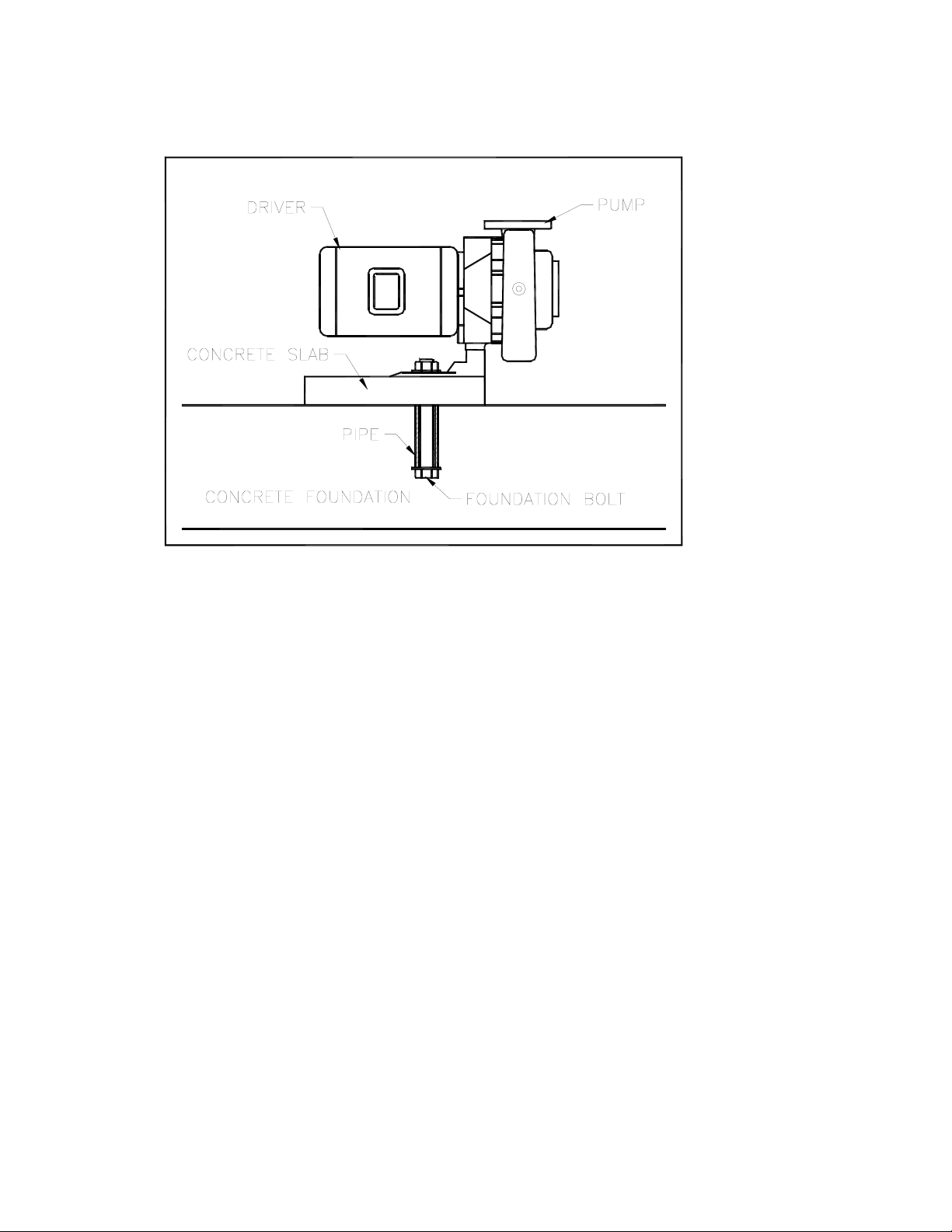
Figure 1
MOUNTING
The pump unit should be set on the foundation, being careful not to damage the threads on the
foundation bolts. The flexible coupling halves should be disconnected. Shims should be inserted
and the pump leveled. A spirit level should be used on the faces of the flexible coupling halves
and on the suction and discharge flanges. If the pump has threaded nozzles, a short piece of
pipe inserted in the nozzles will serve as a smooth surface for a leveling reference point. The
shims should be adjusted until the pump is leveled horizontally and vertically. Tighten the
foundation bolts finger tight.
GROUTING, IF BASE PLATE IS USED
Grouting the base plate prevents lateral movement of the base plate and improves the vibration
absorbing characteristics of the foundation by increasing its mass. A wooden dam should be
constructed around the base plate to contain the grout while it is being poured. The entire base
plate should be filled with grout. Allow 48 to 72 hours for grout to dry. After grout is thoroughly
dried, firmly tighten foundation bolts.
PIPING
The piping practices you follow will directly affect the efficiency and power consumption of your
pump. Pay particular attention to the seemingly insignificant details involved in piping for they
make the difference between a good and bad installation. BOTH THE SUCTION AND THE
DISCHARGE PIPING SHOULD BE INDEPENDENTLY SUPPORTED NEAR THE PUMP;
LIBERAL USE OF PIPE HANGERS AND SUPPORT BLOCKS WILL PREVENT EXCESSIVE
STRAIN ON THE PUMP CASING AND THE PIPE JOINTS. The suction diameter should be at
least the same diameter as the suction nozzle on the pump and preferably larger. Use of a
smaller diameter pipe will result in loss of head due to friction. All joints must be tight to maintain
prime on the pump.
Page 3

SUCTION PIPING
Long radius elbows should be used in place of standard elbows wherever possible, beca use of
their superior flow characteristics. Elbows should not be used at suction nozzle, but if it is
unavoidable, long radius elbows should be used. Elbows installed in any position at the suction
nozzle have a tendency to distribute the liquid unevenly in the impeller eye and may cause a
reduction in capacity, create an undesirable thrust condition, or create noisy operation. Eccentric
reducers should be installed directly at the suction nozzle, with the taper at the bottom to prevent
air pockets from forming. Straight taper reducers should never be used in a horizontal suction
line because of the air pocket that is formed at the leg of the reducer and the pipe.
DISCHARGE PIPING
The discharge pipe diameter should be the same as, or larger than, the discharge nozzle
diameter. The size of the discharge pipe to be used is dependent upon its application,
Long radius elbows should be used in the discharge piping as well as in the suction piping to
prevent excessive head loss due to friction. Whenever possible, elbows should be installed
directly at the discharge nozzle as the turbulence created by the elbow will affect pressure gauge
readings.
An increaser should be installed at the discharge nozzle if larger diameter discharge piping is
used. Straight taper increasers and/or reducers are satisfactory in discharge applications.
CAUTION: PROPER PIPING ALIGNMENT IS ESSENTIAL BEFORE CONNECTION IS MADE,
PIPING ALIGNMENT SHOULD NEVER BE ACHIEVED BY FORCE, THIS COULD PRODUCE
STRAIN ON THE PIPING AND THE PUMP CASING. PROPER SUPPORTS SHOULD BE
INSTALLED FOR THE PIPING TO KEEP ITS WEIGHT OFF THE PUMP CASING.
OPERATION
CAUTION: CENTRIFUGAL PUMPS SHOULD NEVER BE STARTED OR RUN DRY.
OPERATING A PUMP DRY WILL CAUSE SCORING OF THE MECHANICAL SEAL,
RESULTING IN PREMATURE SEAL FAILURE. TO PREVENT THE PUMP FROM BEING RUN
DRY, IT SHOULD BE PRIMED BEFORE STARTING.
PRIMING THE PUMP
The pump will not operate satisfactorily until it is primed. All air must be expelled from the suction
piping and pump casing and replaced by the liquid to be pumped. There are several methods of
priming pumps. The one selected will depend on the specific requirements.
FLOODED SUCTION PRIMING
This method of priming a pump is relatively simple – see Figure 2. The liquid source is located
above the pump and all that is necessary to prime the pump is to open the air vent valve or plug
on the pump casing and to crack the gate valve in the suction line. The suction line and pump
should be filled slowly until a steady stream of liquid is observed flowing from the air vent. After
the pump is operating, it is recommended that the air vent valve or plug be opened again to
insure that all air has been expelled from the pump casing.
SUCTION LIFT
A foot valve should be used for priming on suction lift applications, Figure 2. The foot valve
located at the bottom end or foot of the suction piping functions as a check valve, which allows
flow in one direction only, toward the pump. Otherwise, all the liquid may drain from the pump
and suction piping back into the sump after shutdown.
Initial priming is accomplished by completely filling the suction piping and pump casing with the
liquid to be pumped. This can be done by removing the air vent valve or plug at the top of the
pump casing and inserting a pipe nipple in the orifice with an appropriate increaser to
accommodate a hose connection. A priming line can also be inserted in the discharge piping
Page 4

between the check valve and the pump, or the priming can be done with a bucket and funnel. It
is important to completely fill the suction pipe and pump casing with liquid.
When the pump is started, the vacuum created by pumping the priming fluid combined with
atmospheric pressure in the liquid well forces liquid into the suction piping, thus opening the valve
and keeping it open until the pump is shut down. When the pump is shut down, the liquid being
pumped reverses its flow causing the valve to close. The liquid is now trapped in the suction
piping and pump casing, thus maintaining a prime on the pump.
VACUUM PRIMING
Vacuum priming consists of removing air from the pump casing and suction piping and drawing
liquid into them by means of a vacuum-creating device. The types of vacuum equipment range
from a simple hand pump to a complex central priming system. The specific priming
requirements will govern what type of vacuum primer to use.
STARTING THE PUMP
The discharge gate valve should be partially closed when the pump is started in order to avoid
possible water hammer and initial power draw. As soon as the pump is up to operating speed,
the discharge gate valve should be opened to the desired position. The motor should turn
clockwise when viewed from the motor end and counter-clockwise when viewed from the casing
end.
Figure 2
MAINTENANCE
It is doubtful that a THRUSH pump will ever require complete disassembly. Generally, only
certain components need be disassembled to accomplish inspection or repair.
DISASSEMBLY
Since the THRUSH PC/E-300 & PC2G is of back pull out design, it is unnecessary to disconnect
the piping or casing for service. All service and maintenance can be performed by disconnecting
the coupling and removing the power frame assembly from the casing.
1. Close suction and discharge valves.
2. Break electrical connections to prevent drive unit from being energized during
disassembly.
3. Unscrew two of the pipe plugs (29) from top and bottom of the casing (28).
Page 5

4. Remove all relief, cooling, flushing or drain lines, if present, from the pump.
5. Remove capscrews (30) from bracket (15) and pull bracket assembly from casing (28).
Remove casing gasket (27).
6. Unscrew impeller bolt (35) and remove impeller washer (34), taking care not to damage
gaskets (33 & 36).
7. Slide impeller (37) and impeller key (14) from the shaft, again taking care not to damage
sleeve gasket (23) located behind impeller. Remove sleeve gasket (23).
8. Casing wear ring (39) is pressed into casing (28) with an interference fit and must be
removed with a “puller” if replacement is necessary.
9. If replacing seal cartridge assembly (19,20,21, & 22), slide seal assembly off the shaft.
10. If replacing mechanical seal only (21 & 22), slide seal assembly off the shaft (19).
Remove snap ring (20) at spring end. Remove spring and seal head (22). The rubber in
seal head (22) may be partially adhered to shaft sleeve (19). Remove seat and O-Ring
(21). The sleeve should be carefully cleaned to remove any residue in seal area and
checked for abrasion or corrosion. The sleeve under the seal may be polished lightly to
32 RMS finish before replacing seal assembly (21 & 22). DO NOT REUSE A PITTED
SLEEVE.
11. The seal cavity of the bracket (15) should be cleaned of all residues. Make sure the
1/32-inch radius in the seal cavity is not damaged during disassembly since a sharp edge
can easily cut the O-Ring during re-assembly.
12. Remove capscrews (26) and washers (25) to take off support foot (24).
13. Remove impeller key (14) from the shaft and remove water slinger (66).
NOTE: THE MECHANICAL SEAL IS A PRECISION PRODUCT AND MUST BE TREATED AS
SUCH. DURING REMOVAL, GREAT CARE MUST BE TAKEN TO AVOID DROPPING ANY
PART OF THE SEAL. TAKE PARTICULAR CARE NOT TO SCRATCH THE LAPPED FACES
ON THE WASHER OF THE SEALING SEAT. DO NOT PUT A SEAL BACK INTO SERVICE
UNTIL THE SEALING FACES OF THE WASHER AND SEAT HAVE BEEN LAPPED OR
REPLACED.
REASSEMBLY
1. Mount bracket (15) by screwing capscrews (30) and pipe plug (31) evenly into motor to
assure alignment. Turn the capscrews in an even amount. Attach the bracket support
foot (24) by placing washers (25) over capscrews (26) and screwing them into position.
2. Thoroughly inspect the seal cavity in the bracket for burrs or nicks which could damage
the seat of the seal. APPLY A FILM OF SOAP PASTE OR FLAX SOAP (DO NOT USE
OIL OR GREASE) TO THE SEAT AND O-RING (21).
3. If replacing seal cartridge assembly, remove cardboard spacer and slide assembly (19,
20, 21 & 22) onto motor shaft.
4. If it is not possible to insert seal assembly with fingers, press into place a piece of tubing
with the end cut square and with matching diameter. Tubing should be slightly larger
Page 6

than the diameter of the shaft. Spring tension will probably prevent the sleeve from
remaining in position axially until the impeller is locked against it.
5. When replacing mechanical seal only (21 & 22) wipe the sealing faces of the seat and
seal washer clean. Lubricate these surfaces and shaft sleeve (19) with a clean soap
solution. Put seat and O-Ring (21) on shaft sleeve (19), smooth side to pump end. Slide
the entire rotating assembly onto the sleeve. Carbon in seal head must mate with seal
seat.
6. Replace snap ring (20). The shaft sleeve with the seal rotating assembly on it may not
be replaced onto the pump shaft. Spring tension will probably prevent the sleeve from
remaining in position axially until the impeller is locked against it.
7. Press casing wear ring (39) in casing if change is necessary. Rings should not be
hammered into place. Use a press, or clamp the parts in a bench vise, using wooden
blocks to protect the rings. It may be necessary to pin or dowel the rings after assembly
if the insert of casing has had rings replaced before, since each re-assembly ca n stretch
or tear metal and thereby loosen the fits. If the facilities are available it is good practice
to take a very light finish cut or to ream the inside diameter of the casing rings after
pressing to restore roundness. When rings are pressed, they may get squeezed out of
shape.
8. Replace bracket wear ring (16) in bracket (15), if applicable.
9. Carefully place sleeve gasket (23) on motor end of impeller. Assemble impeller key (14)
and impeller (37) to shaft. Secure impeller with impeller washer gasket (33), impeller
washer (34), impeller bolt gasket (36) and impeller bolt (35),
10. Replace casing gasket (27) on bracket (15). Slide entire motor-bracket assembly into
casing (28) being careful not to damage casing gasket (27). With assembly properly
positioned in casing (28), replace capscrews (30). Turn all capscrews in and tighten
evenly. Replace all hold down bolts securing motor assembly to foundation.
11. Install the two pipe plugs (29) in the pump casing. Position the casing gasket (27) and
casing (28) against the pump bracket and secure with capscrews (30).
12. Replace all relief, cooling, flushing or drain lines.
13. Read carefully the section of the manual titled – INSTALLATION.
14. Connect electricity to the motor.
15. Open suction and discharge valves.
SERVICE
The THRUSH pump requires no maintenance other than periodic inspectio n, occasional cleaning
and lubrication of bearings. The intent of inspection is to prevent breakdown, thus obtaining
optimum service life. The liquid end of the pump is lubricated by the fluid being pumped and
therefore does not require periodic lubrication. The motor, however, may require lubrication, in
which case, the motor manufacturers’ recommendation should be followed.
 Loading...