

Page 1
Manual #9636-1220
Thrush Co.
Air Separators
AS & ASL
Manual # 9636-1220 Rev. A
Operation&MaintenanceManual
340West8thStreet
Peru,IN46970
PH:765‐472‐3351
FX:765‐472‐3968
www.thrushco.com
COPYRIGHTTHRUSHCO.,INC.2014
Page 2

Page 3

Manual #9636-1220
Thrush Co.
Table of Contents
Section No.
Description Page No.
1 General Product Information 1
2
3
Safety Information/Warnings
Component and Operational Information
2
3-6
4 Installation 7-8
5
Maintenance Procedure 9
6 Parts Ordering/Contact Information 9
COPYRIGHT THRUSH CO., INC. 2014
THIS DOCUMENT CONTAINS INFORMATION THAT THRUSH DEEMS CONFIDENTIAL AND PROPRIETARY.
THE BASIC THRUSH PRODUCT REVEALED IN THIS DOCUMENT IS PATENTED, AS ARE CERTAIN PRODUCT
COMPONENTS. IN CONSIDERATION FOR THE RECEIPT OF THIS DOCUMENT, RECIPIENT AGREES NOT TO
REPRODUCE, COPY, USE OR TRANSMIT THIS DOCUMENT OR THE INFORMATION CONTAINED HEREIN, IN
WHOLE OR IN PART, OR TO PERMIT OTHERS TO DO SO, FOR ANY PURPOSE WITHOUT FIRST OBTAINING
THE EXPRESS WRITTEN PERMISSION FROM THRUSH.
Page 4
Thrush Co.
Manual #9636-1220
Section 1
General Product Information
1.1 Overview
The Air Separator separates entrained air from flowing system water by the creation of a
vortex which will allow free air to rise in the center, the point of lowest velocity, to the air
collection chamber in the body of the air elimination valve.
The Thrush Co., Inc. (Thrush) Tangential Air Separator has been carefully assembled
and factory tested to provide years of trouble-free service. This manual provides
information to allow the installer/operator to install, operate, service and maintain the Air
Separator. In this manual the installer/operator will find that two Air Separator models are
covered. Visually these models will look very similar. The major difference between
models is the removable strainer option equipped only on the AS model. The model
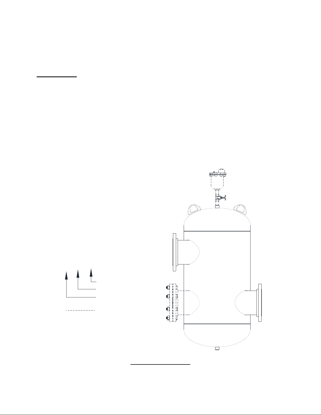
number designates the size of the unit (Figure 1-1).
ModelDesignation
AS(L)‐8
}
Inlet/OutletSize(IN)
Less(without)Screen
AirSeparator
OptionalEquipment
Figure 1-1 Overview
Page 5

Section 2
Safety Information/Warnings
2.1 Safety Information and Warnings
Every practical safety feature has been incorporated into the design and manufacture of
the Thrush Co. Air Separator. If questions are not answered by this manual, or if specific
installation, operation, and/or maintenance procedures are not clearly understood,
contact your local representative before proceeding. Personnel must, at all times,
observe all safety regulations while performing maintenance or repairs.
All installation, operation, and maintenance procedures should be performed by
qualified, experienced and well trained personnel. The potential exists for severe
personal injury if proper procedures are not followed.
Thrush Co.
Manual #9636-1220
System water over 100°F can be very hazardous. Keep flow away from the body
when flushing the unit or removing the strainer. Failure to do so could result in
serious bodily injury or property damage.
4” and larger Air Separators have lift lugs to aid in lifting and locating the unit. The
lift lugs are not intended to be used to support the Air Separators during
operation. Adequately sized and spaced supports/hangers should be used to
prevent damage or strain on the system piping.
With any piece of equipment utilizing boiler water or high temperature water under
pressure, there is a potential for severe personal injury or death if proper
installation, operation and maintenance procedures are not followed.
Page 6

Thrush Co.
Manual #9636-1220
3.1 AS/ASL Component Identification
The major difference between the Air Separator AS/ASL models, is that the AS model
comes equipped with a removable strainer for maintenance.
Section 3
Component and Operational Information
OUTLET
INLET
STRAINER
304S.S.
51%OPEN
ASL
INLET
OUTLET
AS
Figure 3-1 AS/ASL Components
Page 7

3.1.1 Removable Strainer Option
The removable strainer option is a rolled 304 stainless perforated cylinder that allows the
user to easily remove the strainer for cleaning and /or inspection (Figure 3-2).
System water over 100°F can be very hazardous. Keep flow away from the body
when flushing the unit or removing the strainer. Failure to do so could result in
serious bodily injury or property damage.
Manual #9636-1220
Thrush Co.
Figure 3-2 Strainer
3.2 Optional Connections
The standard inlet and outlet flanged connections can be replaced with an alternate
grooved end pipe connection (Figure 3-3). This comes with or without strainer option.
FLANGEDNOZZLEFOR
ASMODELONLY
Figure 3-3 Grooved End Connection
Page 8

Thrush Co.
Manual #9636-1220
3.3 Suggested Equipment
Although the standard Air Separator is a simple design, a Thrush Model 720 Air
Eliminator is recommended to vent air from the system.
3.3.1 Model 720 Air Eliminator
The Model 720 Air Eliminator is a unique high capacity, air elimination device. It is
designed to eliminate air as fast as it can be separated from liquid. The valve will not
open if negative pressure occurs, preventing air from being drawn back into the system.
DRAINTAP
3
"NPT
8
CONTROLASSEMBLY
LEVERASSEMBLY
VALVETAP
1
"NPT
4
LID
5
7
"
8
3
"NPT
4
BODY
FLOAT
AIRCOLLECTION
CHAMBER
6"
Figure 3-4 Model 720 Air Eliminator
Operation
The air eliminator is designed to remove unwanted air that could reduce system
performance, increase operational cost, and support the damaging effects of
corrosion.
The collection of air in the body of the air eliminator causes the float to drop
allowing the air to be vented through an air eliminating orifice. As the liquid level
rises in the eliminator body, the float also rises shutting off the flow of vented air
(Figure 3-4)
Page 9

3.3.1 Model 720 Air Eliminator (Continued)
Installation Tips
1. The Model 720 Air Eliminator should be located in a clean, open area, where it is
easily accessible for inspection, service and repair.
2. The Model 720 Air Eliminator should be installed at the top of each air separator
(Figure 3-5), or it may be installed at the system piping highest point with a pipe
run from the air separator.
3. Additional Model 720 Air Eliminators are recommended for each component and
pipe locations where air could accumulate.
4. A shut off valve should be provided to simplify cleaning and replacement of float
and control assembly if necessary. Valve should remain open during normal
operating processes.
Manual #9636-1220
Thrush Co.
SHUTOFF
VALVE
DRAINLINETO
DRAIN/SINK/
ORCONTAINER
TOPUMP
FROM
SYSTEM
Figure 3-5 Model 720 Air Elimination Installation
(ASModelShown)
Page 10

Thrush Co.
Manual #9636-1220
4.1 Installation Tips
The following procedures are to aid the operator in installing the Air Separator. All
procedures are to be performed by experienced, trained, and certified personnel only.
4” and larger Air Separators have lift lugs to aid in lifting and locating the unit. The
Some considerations: Isolation valves are required to allow gasket changes and
inspection of strainer. Expansion joints and or flex connectors are recommended to
prevent pipe strain caused by thermal expansion or piping misalignment. System bypass piping is also recommended in the event of system service and or maintenance.
Section 4
Installation
lift lugs are not intended to be used to support the Air Separators during
operation. Adequately sized and spaced supports/hangers should be used to
prevent damage or strain on the system piping.
1. The Air Separator should be located in a clean, open area, where it is easily
accessible for inspection, service and repair. Installation of the unit in an area with
adequate drainage is recommended.
2. A standard Air Separator is installed in-line of the system piping. Adequately sized
and spaced pipe supports/hangers should be used to prevent damage or strain on
the system piping.
3. When placing the Air Separator (AS Model) with strainer in the system piping, be
aware of the clearance required for strainer removal for cleaning and replacement
4. When piping the unit into system piping, the pipe size should be sized to allow
adequate flow at a minimal head loss, and be, at minimum, the same size as the
Air Separator connections. The use of fittings (elbows, tees and couplings) should
be kept to a minimum as well.
With any piece of equipment utilizing boiler water or high temperature water under
pressure, there is a potential for severe personal injury or death if proper
installation, operation and maintenance procedures are not followed.
Page 11

Thrush Co.
4.2 Installation Tips (Continued)
Using the figure below as reference, follow the steps outlined to install piping for the Air
Separator (Figure 4-1, shown with AS Model). Before making any piping connections,
ensure that all piping is clean and free of any foreign material such as debris or scale.
Foreign material in the piping can cause damage to the unit and/or affect the
performance and operation. Manual shutoff valves should be installed
upstream/downstream from all connections to act as an isolation device. These valves
should be in the closed position and remain so until the installation is complete.
Expansion joints and/or flex connectors are recommended to prevent pipe strain caused
by thermal expansion or piping misalignment.
MODEL720AIRELIMINATOR
LIFTLUGS(2)
(4"&LARGER)
ISOLATIONVALVE
RETURN
INLET
ISOLATION
COLD
WATER
SUPPLY
AUTOMATIC
FILLVALVE
VALVE
DRAIN
DRAIN
OUTLET
Manual #9636-1220
AIRSEPARATOR
FLEXCONNECTOR(S)
SUPPLY
TRI‐FLOWVALVE
BOILER
TANK
SUCTIONDIFFUSER
Figure 4-1 Typical Piping Diagram
1. Connect the supply source to the inlet connection of the Air Separator. Be sure
the upstream manual shutoff valve is in the closed position (Figure 4-1).
2. Connect the suction piping of the pump to the outlet connection of the Air
Separator. Be sure the downstream manual shutoff valve is in the closed position
(Figure 4-1).
PUMP
Page 12

Thrush Co.
Manual #9636-1220
5.1 Maintenance Procedure
Because of the simple design of the Air Separator, minimal maintenance is necessary.
Periodical inspections by competent personnel for signs of corrosion, defects or cracks
are suggested. Examine the strainer (if applicable) for any debris, especially during initial
start-up period. Contact your representative for replacement gaskets and/or strainers.
6.1 Contact Information
Any additional information not supplied in this manual can be given by your
representative.
If your representative cannot be reached, please contact our customer service
department:
When calling or writing to place a parts order to your representative, it is recommended
to have the following items for reference:
Section 5
Maintenance Procedures
Section 6
Maintenance Procedures
Thrush Co., Inc.
PO Box 228
340 West 8th Street
Peru, IN 46970
Attention: Customer Service Group
Phone: (765) 472-3351
(800) 755-8110
Fax: (765) 472-3968
E-mail: customerservice@thrushco.com
1. Part number(s).
2. Description of product(s).
3. Quantity required.
4. National Board Number (if applicable).
 Loading...