

Page 1

INSTALLATION INSTRUCTIONS FOR
THRUSH KIT: 89021
1967-74 Chevrolet Camaro / Pontiac Firebird V8
(Exc. Convertible)
1967-74 Chevrolet Nova V8
2701 N. Dettman Rd.
Jackson, MI 49201
DANGER WARNING: SHOULD THE PURCHASER DECIDE TO INSTALL ANY
EXHAUST PRODUCT AT HOME, BE WARNED THAT PASSENGER CAR OR
LIGHT DUTY TRUCK/VAN “BUMPER” JACKS ARE INTENDED FOR EMERGENCY USE ONLY.THE USE OF FRAME CONTACT JACK STANDS IN CONJUNCTION WITH A FLOOR JACK AS MAIN SUPPORT IS HIGHLY RECOMMENDED TO MINIMIZE ACCIDENTAL DROPPING OF A VEHICLE DURING THE
INSTALLATION PROCESS.
NOTE: Read all instructions before starting any work. This kit is designed to connect to
DynoMax Blackjack painted or Cyclone Ceramic coated, or competitive brand,
full length Headers.
1. Position the Thrush muffler 704093 behind the rear axle in the stock location and support
with a floor jack.
2. Install the intermediate pipes, 704089 RH and 704090 LH, into the muffler inlet
connections. See the system diagram for muffler inlet locations. (NOTE: The muffler can
be installed with any set of connections as the inlet or outlet.) Finger tighten the 2¹⁄₂"
clamps that secure each pipe to the muffler inlet connections.
3. Install the 704088 h-pipe into the intermediate pipes and tighten 2¹⁄₂” clamps enough to
hold the pipes in place but still allow adjustments. Temporarily support these pipes.
4. Install reducer adapters 703094, flanges 160771, and gaskets 160401 onto the header
collectors and attach with the ³⁄₈" nuts, lock washers, and bolts provided.
5. Hold the front header extension pipe 704087 up to the reducer adapters and the
h-pipe704088. Measure the extension pipes for possible cut-off.You may need to cut-off
on each end for best fit. Once the cut-offs have been made, clamp the extension pipes to
the reducer adapters and h-pipe. You may need to remove the reducer adapters from the
headers to insert the extension pipes and clamp properly. Support these pipes with jack
stands or similar supports. Please see the system diagram.
6. Make sure the muffler is now centered tin the area behind the rear axle.
7. Position a 35819 hanger above each intermediate pipe (704089 RH & 704090 LH) just
before the bend that starts up over the rear axle. Lightly clamp these to each pipe so that
you can locate the holes to be drilled into the floor pan to secure hangers.
8. Raise the muffler and pipes up until the hanger rubber pieces make contact with the
bottom of the floor pan. The two rubber pieces of the hanger must be folded together so
that the two holes line up. Use the flat metal plate and place this on top of the rubber
pieces for reinforcement. Mark the location of the holes with a center punch.
9. Drill out the holes using a ⁵⁄₁₆" drill. You will want to remove the back seat so that you can
get to the hole locations. Attach the hangers with the bolts, lock washers, and hex nuts
provided.
10. You should now be able to let the system be supported by these two hangers.
11. Inser t the 704091 RH tail pipe and 704092 LH tail pipe into the muffler outlets. Finger
tighten the 2¹⁄₂" clamps that connect the tail pipes to the muffler outlets. The inlet of the
tail pipes may need to be trimmed to obtain proper fit between the leaf springs and the
body panels. Temporarily support the weight of the muffler again.
12. Install the 35625 hangers at the top of each tail pipe near where each clamps into
muffler.You may want to use a second clamp to attach the hanger to each tail pipe. After
clamping, locate the hanger to the floor pan so an attachment hole can be drilled. Drill a
³⁄₁₆" hole in the floor pan on each side so a ¹⁄₄" self tapping screw can be used to secure
the hangers. You may also drill a ⁵⁄₁₆ hole and use a regular bolt, lock washer and hex nut
See included photograph.
13. Remove the temporary muffler support and let the system hang.
14. Beginning at the inlet end, align all system components and tighten all
connections.
15. See system diagram on the back page of these instructions.
Form: 704103
12/06
KIT CONTAINS:
(1) 704093 MUFFLER
(2) 703094 ADAPTERS
(2) 704087 EXT. PIPES
(1) 704088 H-PIPE
(1) 704092 LH TAIL PIPE
(1) 704091 RH TAIL PIPE
(2) 35625 HANGERS
(2) 35819 HANGERS
(1) 704089 RH INT. PIPE
(1) 704090 LH INT. PIPE
(1) 703997 FASTENER KIT
(2) 160401 GASKETS
(2) 160771 FLANGES
(12) 2¹⁄₂" SADDLE CLAMPS
(1) 704103 INSTRUCTION SHEET
703997 FASTENER KIT includes
(6) ³⁄₈" x 1¹⁄₄" BOLTS
(6) ³⁄₈" HEX NUTS
(6) ³⁄₈" LOCK WASHERS
(4) ⁵⁄₁₆" HEX NUTS
(4) ⁵⁄₁₆" FLAT WASHERS
(4) ¹⁄₄" x 1" SELF TAPPING SCREWS
(4) ⁵⁄₁₆" LOCK WASHERS
Page 2
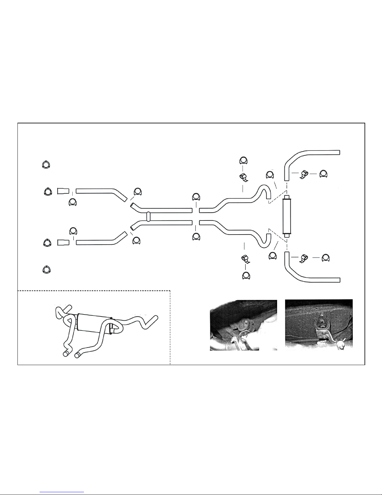
89021 SYSTEM DIAGRAM
Form: 704103
12/06
160401
160401
160771
160771
703094
703094
2¹⁄₂"
Clamp
2¹⁄₂"
Clamp
OUTLET
704087
704087
2¹⁄₂"
Clamp
2¹⁄₂"
Clamp
2¹⁄₂"
Clamp
2¹⁄₂"
Clamp
704088
704089
704090
2¹⁄₂"
Clamp
2¹⁄₂"
Clamp
2¹⁄₂"
Clamp
2¹⁄₂"
Clamp
2¹⁄₂"
Clamp
2¹⁄₂"
Clamp
704093
704091
704092
35819
35819
35625
35819
Top
Top
Bottom
Bottom
OUTLET
INLET
704091
704089
704090
704092
AUXILLARY VIEW
35625 installed on the LH tail pipe. 35819 installed on the RH int. pipe.
 Loading...