

Page 1
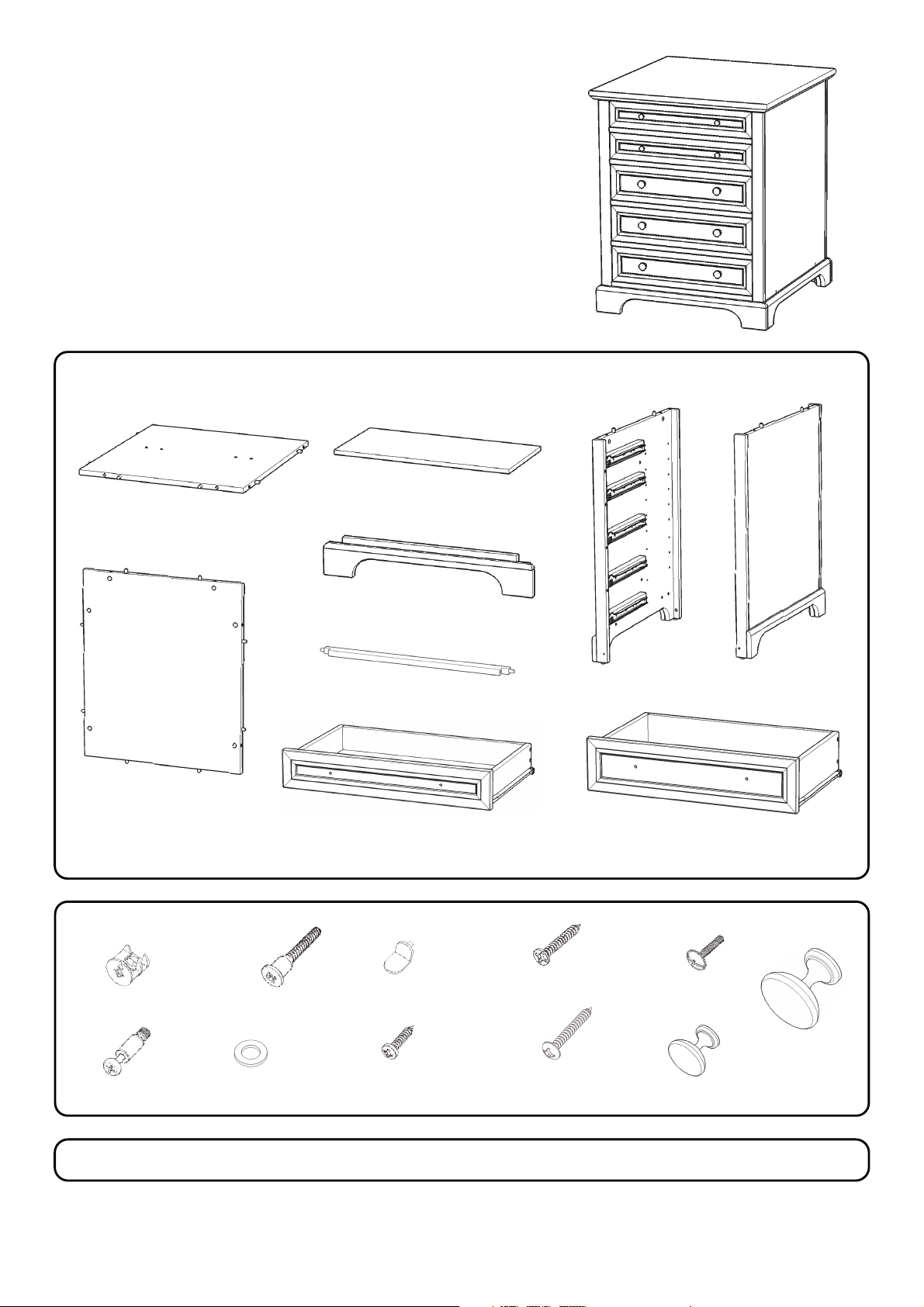
Storage Island
IMPORTANT
Carefully remove all the parts from the carton and
place them individually on a soft cloth to prevent
scratches or other damage.
Carefully and strictly follow these assembly instructions
to ensure a completed product as designed.
Do not use power tools above 8 volts to assemble.
Part List
C.
B.
Bottom
1 pc.
Shelf
3 pcs.
F.
Back Panel
1 pc.
Hardware List
Cam Lock
26 pcs.(+6 extra)
I.
Drawer
2 pcs.
M6x35
Bolt
2 pcs. (+1 extra)
G.
Plinth
2 pcs.
H.
Front Rail
4 pcs.
Adjustable Pin
12 pcs. (+1 extra)
M3x25
Wood Screw for
Side Panels
4 pcs. (+1 extra)
J.
Drawer
3 pcs.
D.
Side Panel
1 pc.
Refer to the last page(s) of these
Instructions for drawer assembly.
M4x28
Machine Screw
10 pcs.
E.
Side Panel
1 pc.
M3.5x25
Wood Screw (long)
for Drawer Side
40 pcs. (+1 extra)
Knob (small)
4 pcs.
Cam Lock Screw
26 pcs.(+1 extra)
Flat Washer
2 pcs. (+1 extra)
M3.5x16
Wood Screw (short)
for Drawer Bottom
30 pcs. (+1 extra)
Carton is also needed for assembly.
Tool(s) required for assembly: Phillips screwdriver, Level, Drill (8 volts or less), 3/8” Drill Bit
Knob (large)
6 pcs.
Page 2
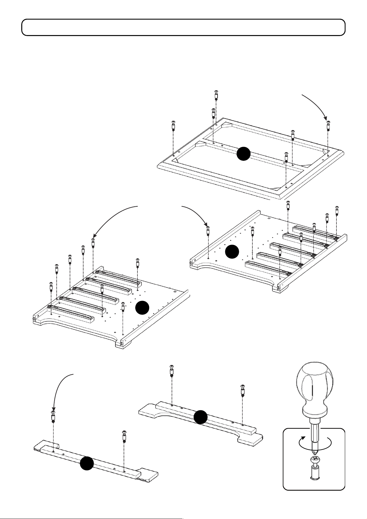
Assembly Instructions 2/7
IMPORTANT
Use a soft cloth between these parts and the floor.
Do not use power tools above 8 volts to assemble.
Do not tighten all the bolts until each part is properly assembled.
The unit must be level to work properly. Use the included adjustable levelers to level.
STEP 1
Put Cam Lock Screws into
the pre-drilled holes of Top (A),
Side Panels (D), (E) and Plinths (G),
then tighten. (See Figure 1)
Cam Lock Screw
Cam Lock Screw
A
Cam Lock Screw
E
D
G
G
Figure 1
Page 3
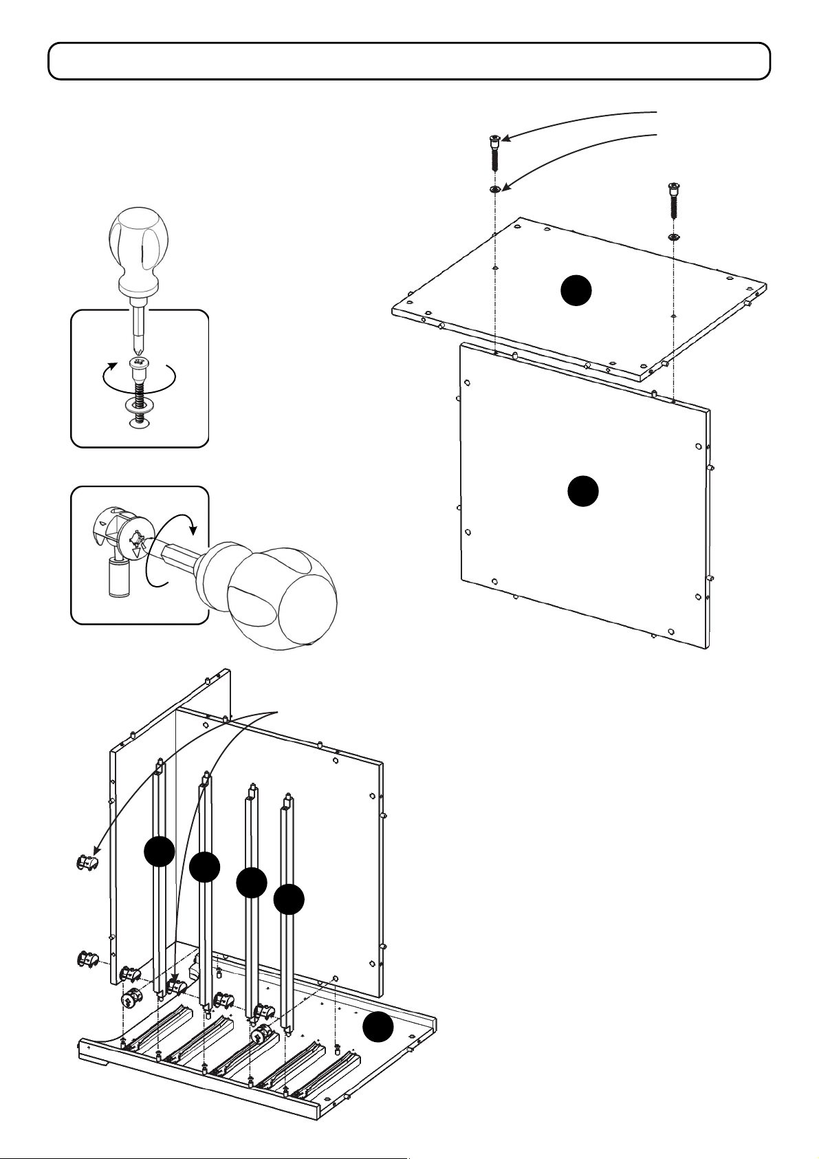
Assembly Instructions 3/7
STEP 2
Attach Bottom (B) to Back Panel (F) with
Flat Washers and Bolts. (See Figure 2)
Figure 2
Bolt
Flat Washer
B
F
Figure 3
H
H
H
Cam Lock
H
E
STEP 3
Attach unit to Side Panel (E) with
Cam Locks. (See Figure 3)
Attach Front Rails (H) to Side Panel (E)
with Cam Locks.
Page 4
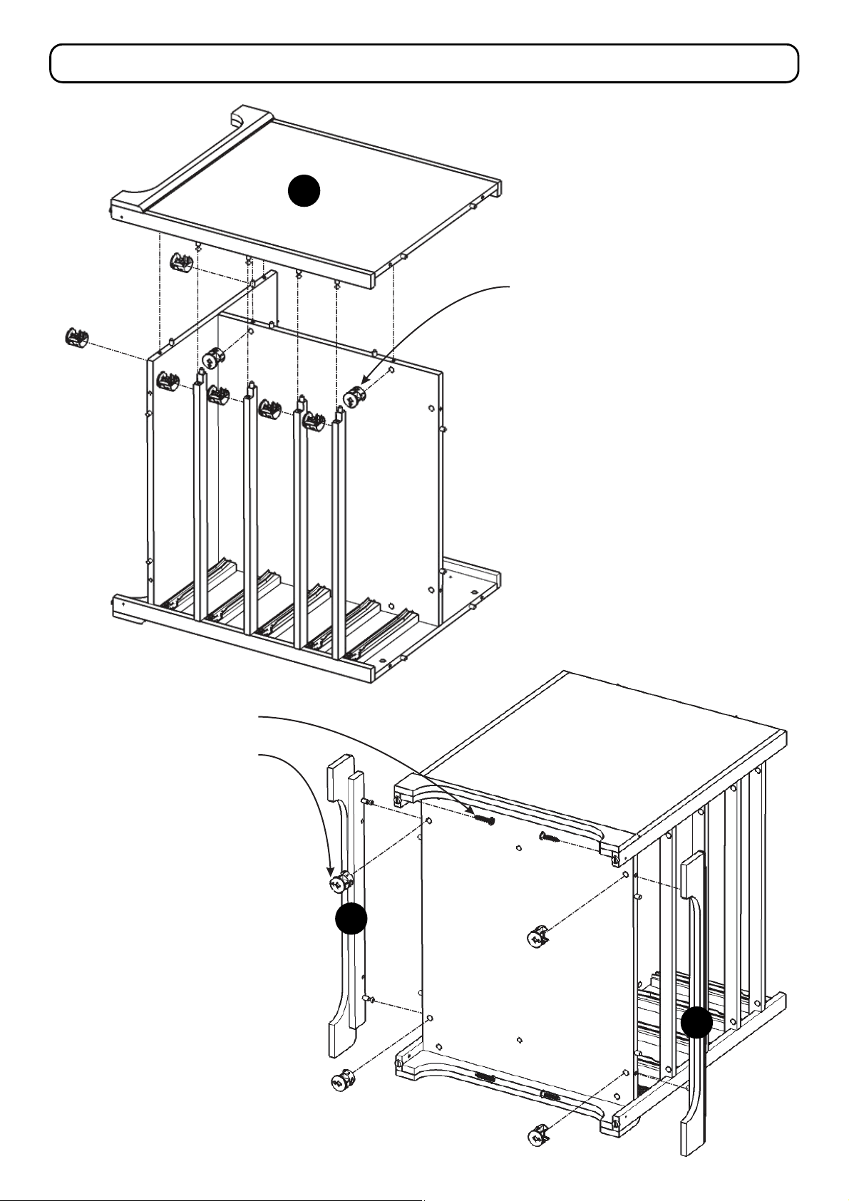
Assembly Instructions 4/7
D
Cam Lock
STEP 4
Attach Side Panel (D) to unit with
Cam Locks.
Wood Screw
for Side Panel
Cam Lock
STEP 5
Attach Plinths (G) to unit with
Cam Locks and Wood Screws
for Side Panel.
G
G
Page 5
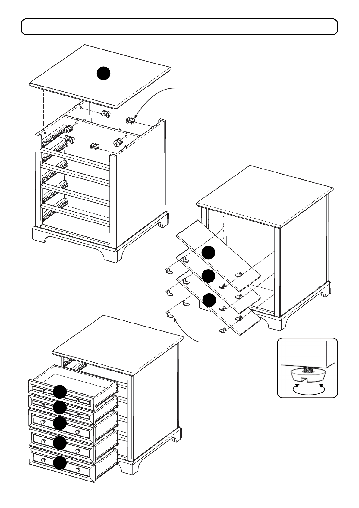
Assembly Instructions 5/7
A
Cam Lock
STEP 6
Attach Top (A) to unit with
Cam Locks.
STEP 7
Insert Adjustable Pins into side panels
at desired level, then place Shelves (C)
into position.
I
I
J
C
C
C
Adjustable Pin
Figure 4
STEP 8
J
J
Slide Drawers (I) and (J) into position.
To level the unit, adjust the adjustable levelers
on the bottom of unit. (See Figure 4)
Note: Unit must be level to work properly.
Page 6
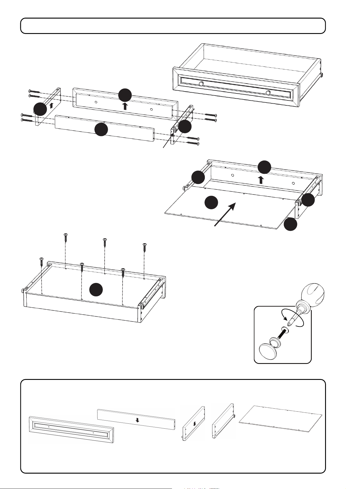
Drawer (I)
I3
Assembly Instructions 6/7
I1
I2
STEP 1
Attach Drawer Front (I1) and Drawer
Back (I2) to Drawer Side (I3) with
Wood Screws (long).
Attach Drawer Side (I4) to unit with
Wood Screws (long).
I5
Roller at back
I4
I1
I3
I5
I2
STEP 2
Slide Drawer Bottom (I5) into the grooves
of Drawer Sides (I3) and (I4) until it meets
Drawer Front (I1).
I4
STEP 3
Attach Drawer Bottom (I5) to unit with
Wood Screws (short).
Part List
I1.
Drawer Front
2 pcs.
I2.
Drawer Back
2 pcs.
STEP 4
Attach Knobs (small)
with Machine Screws.
I3.
Drawer Side
2 pcs.
I4.
Drawer Side
2 pcs.
I5.
Drawer Bottom
2 pcs.
Page 7
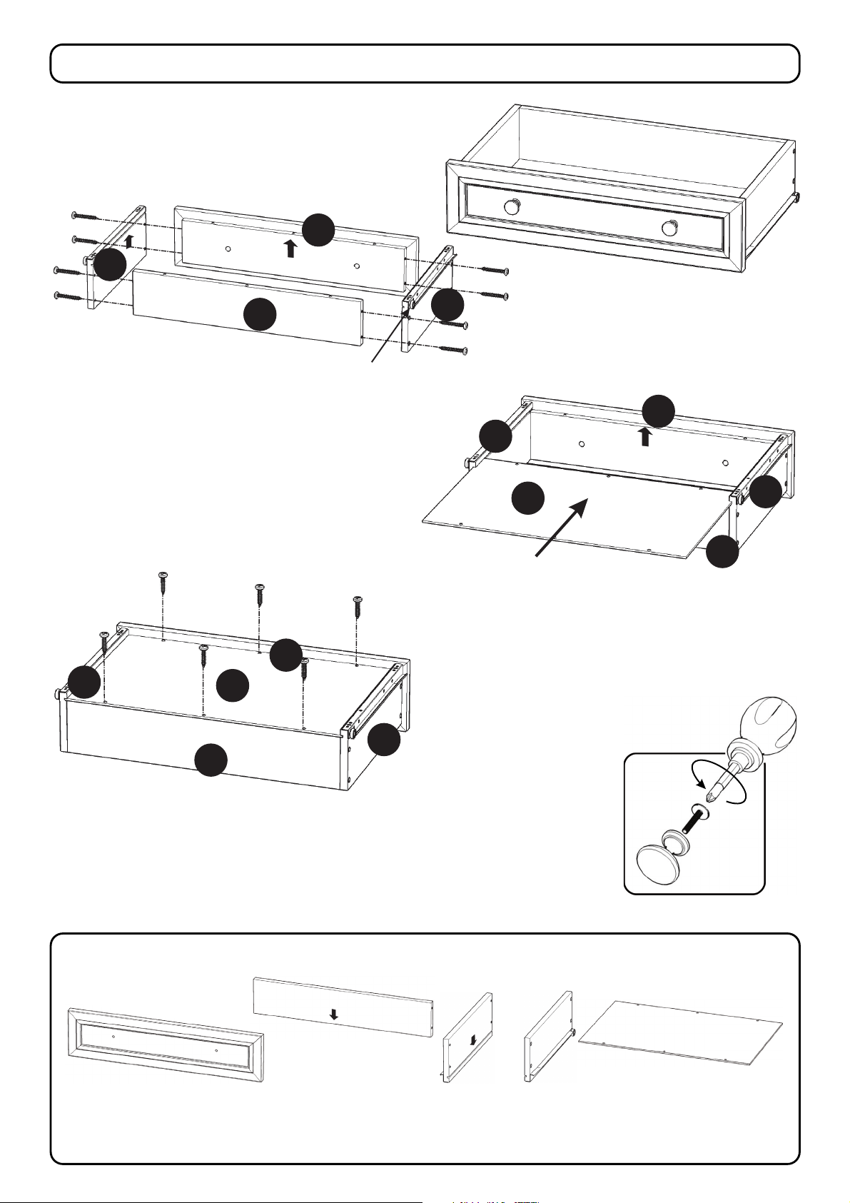
Drawer (J)
J3
Assembly Instructions 7/7
J1
J2
STEP 1
Roller at back
Attach Drawer Front (J1) and Drawer
Back (J2) to Drawer Side (J3) with
Wood Screws (long).
Attach Drawer Side (J4) to unit with
Wood Screws (long).
J1
J3
J5
J4
J1
J3
J5
STEP 2
Slide Drawer Bottom (J5) into the grooves
of Drawer Sides (J3) and (J4) until it meets
Drawer Front (J1).
J4
J2
J2
STEP 3
Attach Drawer Bottom (J5) to unit with
Wood Screws (short).
Part List
J1.
Drawer Front
3 pcs.
J2.
Drawer Back
3 pcs.
J4
STEP 4
Attach Knobs (large)
with machine screws.
J3.
Drawer Side
3 pcs.
J4.
Drawer Side
3 pcs.
J5.
Drawer Bottom
3 pcs.
Page 8
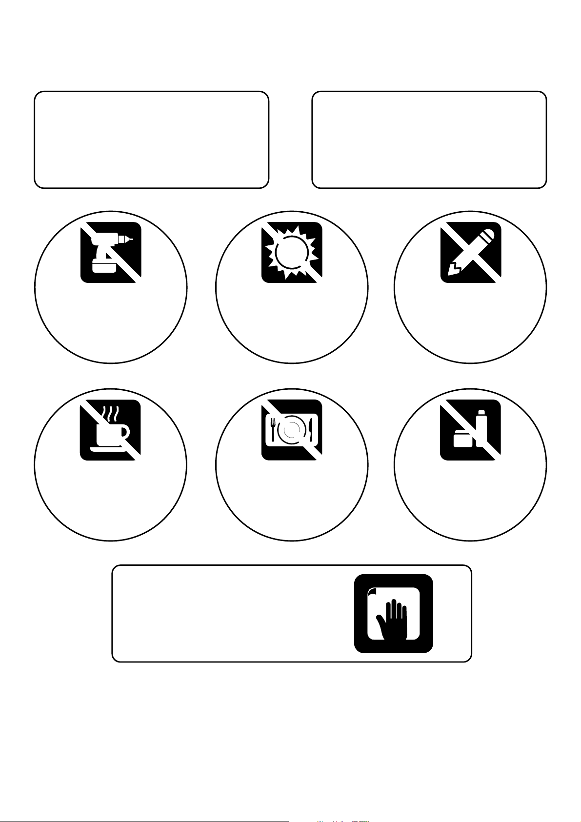
CARE INSTRUCTIONS
NEVER
allow liquids to remain on furniture.
Absorption causes parts to warp
and split and finishes to delaminate.
Do not use power tools
above 8 volts to assemble.
PREVENT
CRACKING
Do not place
in direct sunlight.
PREVENT
FADING
NEVER
use glass cleaners on
finished furniture. Ammonia
chemically attacks the finish.
Do not write
directly on surface.
PREVENT
MARKING
Do not place hot
objects on surface.
PREVENT
FINISH DAMAGE
Do not use rubber
based placemats.
PREVENT
DISCOLORING
Do not use commercial
waxes and polishes.
PREVENT
YELLOWING
CLEAN
with a soft cloth moistened
in lukewarm soap and water.
Buff with a dry clean cloth.
We will provide replacements free of charge for missing or damaged hardware or parts within 30 days of
purchase. Digital images of the defective parts may be required. If the product was not purchased from an authorized
retail affiliate, weareunder noobligation to provide replacement parts. Parts are not availablefor fully assembleditems
nor are parts availablefor sale. Replacements for missing ordamaged hardware or partsmay be requested at our web.
 Loading...