

Page 1
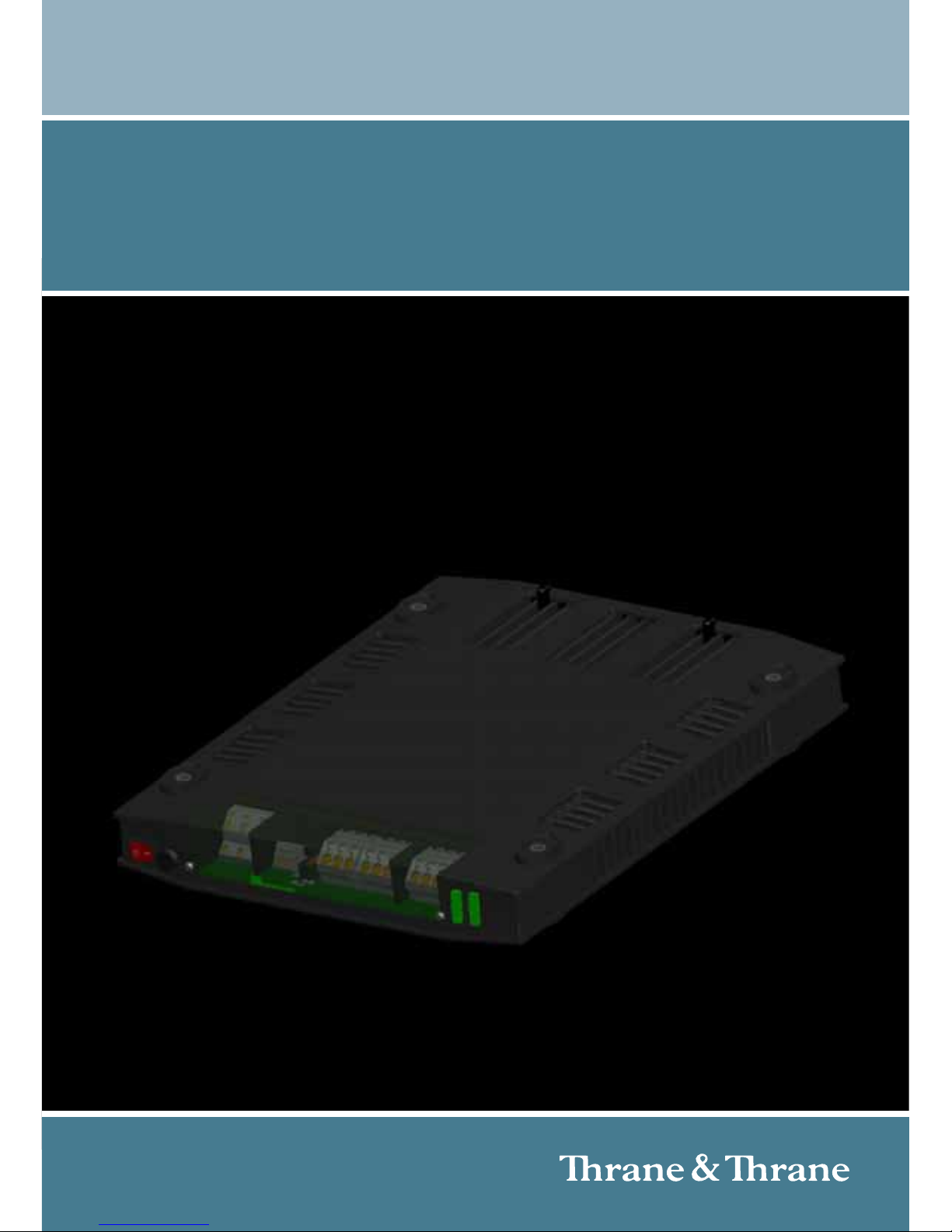
AC/DC Power Supply
INSTALLATION MANUAL
Page 2

Page 3

Thrane & Thrane A/S
AC/DC Power Supply
Installation Manual
Document number: 98-129099-C
Release date: February 26, 2010
Page 4

Disclaimer
Any responsibility or liability for loss or damage in connection with the use of this
product and the accompanying documentation is disclaimed by Thrane & Thrane. The
information in this manual is provided for information purposes only, is subject to
change without notice and may contain errors or inaccuracies. Manuals issued by
Thrane & Thrane are periodically revised and updated. Anyone relying on this
information should acquire the most current version e.g. from http://www.thrane.com or
from the distributor. Thrane & Thrane is not responsible for the content or accuracy of
any translations or reproductions, in whole or in part, of this manual from any other
source.
Copyright
© 2010 Thrane & Thrane A/S. All rights reserved.
DISPOSAL
Old electrical and electronic equipment marked with this symbol can
contain substances hazardous to human beings and the environment.
Never dispose these items together with unsorted municipal waste
(household waste). In order to protect the environment and ensure the
correct recycling of old equipment as well as the re-utilization of individual components,
use either public collection or private collection by the local distributor of old electrical
and electronic equipment marked with this symbol.
Contact the local distributor for information about what type of return system to use.
Page 5
iii
Safety summary 1
The following general safety precautions must be observed during all
phases of operation, service and repair of this equipment. Failure to comply
with these precautions or with specific warnings elsewhere in this manual
violates safety standards of design, manufacture and intended use of the
equipment. Thrane & Thrane assumes no liability for the customer's failure
to comply with these requirements.
Observe marked areas
Under extreme heat conditions do not touch
areas of the unit that are marked with this
symbol, as it may result in injury.
KEEP AWAY FROM LIVE CIRCUITS
Operating personnel must not remove equipment covers. All repair and
servicing tasks must be made by qualified maintenance personnel. Do not
service the unit with the power cable connected. Always disconnect and
discharge circuits before touching them.
MAKE SURE THE UNIT IS GROUNDED DURING OPERATION.
Warning! Never insert or remove a power supply while its power
switch is in the On (|) position. Make sure the power
switch is Off (O) first.
Page 6

iv
About the manual 2
Intended readers
This manual is an installation and user manual for the AC/DC
Power Supply system. It is important that you observe all safety
requirements listed in the beginning of this manual, and operate
the AC/DC Power Supply according to the instructions and
guidelines in this manual. All installation must be done by
qualified service personnel.
Manual overview
This manual has the following chapters:
• Introduction contains a description of the principle of operation
and uses and features of the power supply.
• Installation contains step-by-step guidelines how to install the
power supply as a stand-alone unit or in a combined setup and
describes the connectors.
• Service and repair contains information on support, how to
return units for repair and instructions how to exchange the
fuses.
Typography
In this manual, typography is used as indicated below:
Bold is used to emphasize words and to indicate connector names
of the unit.
Italic is used to emphasize the paragraph title in cross-references.
Example: “For further information, see Connecting Cables on
page...”.
Page 7

v
Table of Contents
Chapter 1 Introduction
General description ............................................................ 1
Features .............................................................................2
Block diagram ....................................................................3
Applications .......................................................................4
Chapter 2 Installation
Unpacking ..........................................................................5
Installing the AC/DC Power Supply .....................................6
Installing 2 or 3 AC/DC Power Supply units .......................15
Chapter 3 Service and repair
Contact for support ............................................................17
Repair and servicing .........................................................17
Exchanging the fuses ....................................................... 18
Returning units for repair ..................................................19
Page 8

Table of Contents
vi
App. A Technical specifications
App. B Wall-mount tray (option)
App. C Special installation
App. D Declaration of conformity
Glossary
......................................................................................... 31
Index .........................................................................................33
Page 9

1
Chapter 1
1111
Introduction
Introduction 1
General description
The TT-6080A AC/DC Power
Supply can deliver 300 W
output power on average
with a peak of 370 W for a
minimum of 2 minutes.This
is useful for MF/HF
applications and DSC
transmissions of 2 minutes
duration. It is AC powered
with a battery switch-over function. The AC/DC Power Supply has an on/off
switch. It is lit when the power is turned on.
All connectors are placed at the same end of the power supply to simplify
mounting and installation. The connector panel is protected by a transparent
lid. To secure an installation with heavy cables a cable-relief bracket can be
installed.
When mounted vertically the AC/DC Power Supply fulfills IP32 in areas with
more than 42 V and IP22 in other areas. This means that the unit is protected
against the intrusion of solid objects (including body parts like fingers), dust,
water etc.
Page 10

Chapter 1: Introduction
2Features
Features
The AC/DC Power Supply has the following features:
IEC 60945 Maritime approval
Two DC connectors, output, range: 28.7 V - 31.2 V
Output power 300 W continuous, 370 W peak (2 min., 100-240 VAC) or
270 W continuous, 333 W peak (2 min., 90-100 VAC)
AC input (100-240 VAC operating) with fuse (6.3 A)
Automatic selection of input voltage range
AC alarm and On/off switch
Daisy-chaining of up to three units to give up to 900 W.
1
Short circuit protection
Over-temperature protection (shutdown with automatic restart)
Battery switch-over in case of AC supply failure, secured by 2 fuses (30 A)
No forced cooling required
IP 3X for internal high voltage areas (>42 V), IP 2X in other areas
IP X2 when vertically mounted (wall) and connector panel is facing down
1. Output power capability depend on the mounting position (horizontal or
vertical), input voltage, ambient temperature and ventilation at the place of
installation.
Page 11
Chapter 1: Introduction
Block diagram 3
1111
Introduction
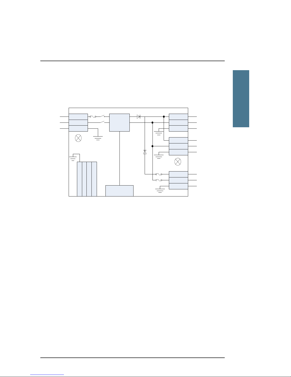
Block diagram
The drawing below shows the block diagram of the AC/DC Power Supply.
L
N
GND
Mains AC
AC Input
DC+
DC-
DC1
28.7-31.2 VDC
output
DC+
DC-
DC2
28.7-31.2 VDC
input / output
Battery+
Battery-
AC LED
Output LED
24 VDC
Battery input
GND
NC : Open when ok
COM: Common
AC/DC
converter
GND
GND
GND
I/O connec tor,
for future use
AC ALARM
AC alarm output
NO: Closed when ok
GND
Page 12
Chapter 1: Introduction
4 Applications
Applications
The AC/DC Power Supply is designed
to be used with BGAN-X and
FleetBroadband terminals. It can be
used as a stand-alone DC power
supply or as a building block in a
larger power supply.
When more power is needed than one
power supply can give, i.e. 300 W, you
can stack up to three power supplies
on top of each other and connect them.
When stacking 2 or 3 units the load on
each of the units is automatically
balanced among the units.
Page 13

5
Chapter 2
2222
Installation
Installation 2
The AC/DC Power Supply can be mounted on its own as a single unit, or you
can daisy-chain and stack up to 3 units. The AC/DC Power Supply can also be
fitted in a 1 U rack mount.
Unpacking
• TT-6080A AC/DC Power Supply
•1 AC fuse, 6.3A
• 2 battery fuses, 30 A
• 4 mounting bolts for mounting 1 unit, M6X55 mm, DIN912 Unbrako
• Cable-relief bracket, comb-style
• AC/DC Power Supply Installation manual (this manual)
Optional accessories
The following optional accessories are available and can be ordered:
• Wall-mount tray, heavy duty, with cable-relief bracket, order number:
406080A-opt.001
• 4 mounting bolts for mounting 2 AC/DC Power Supply units, M6X100 mm,
DIN912 Unbrako, order number: 406080A-opt.002
• 4 mounting bolts for mounting 3 AC/DC Power Supply units, M6X140 mm,
DIN912 Unbrako, order number: 406080A-opt.003
Page 14
Chapter 2: Installation
6 Installing the AC/DC Power Supply
Installing the AC/DC Power Supply
You can mount the power supply in a vertical or horizontal position. When
mounted in a vertical position, with the connector panel pointing downwards,
the unit fulfills IP32 in areas with more than 42 V and IP22 in other areas.
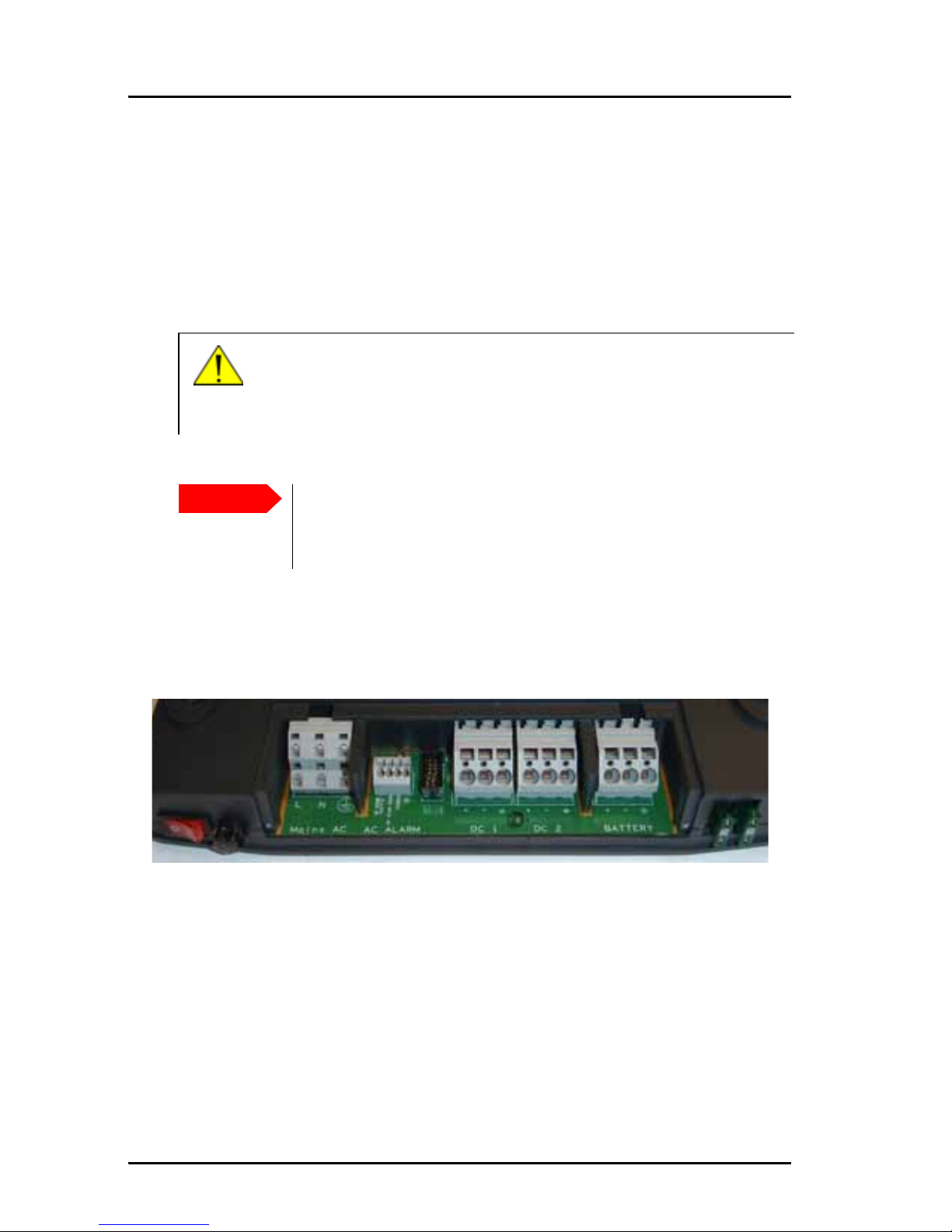
Connector overview
Warning! Never insert or remove a power supply while its power
switch is in the On (|) position. Make sure the power
switch is Off (O) first.
Important
To ensure adequate cooling of the AC/DC Power Supply an
unobstructed space of minimum 5 cm must be maintained
around all sides of the unit except for the bottom side.
On/off
AC input
AC alarm
DC 1
DC 2
Battery
switch
Page 15

Chapter 2: Installation
Installing the AC/DC Power Supply 7
2222
Installation
Outline and dimensions
The following drawing shows the AC/DC Power Supply and the position of the
mounting holes. It is mounted with four mounting bolts.
• 4 mounting bolts for mounting 1 unit, M6X55 mm, DIN912 Unbrako
Page 16

Chapter 2: Installation
8 Installing the AC/DC Power Supply
To install the AC/DC Power Supply, do as follows:
1. Install the cable-relief bracket, if required. Align it with the connector row
of the AC/DC Power Supply.
2. Fasten the cable-relief bracket directly to the wall, between the wall and
the AC/DC Power Supply, with four M4 x 6 mm screws.
3. Fasten the AC/DC Power Supply to the wall with 4 mounting bolts,
M6X55 mm, DIN912 Unbrako (included the delivery).
An optional, larger Wall-mount tray, heavy duty, is available for the AC/DC
Power Supply. For further details see Wall-mount tray (option) on page 25.
Page 17

Chapter 2: Installation
Installing the AC/DC Power Supply 9
2222
Installation
Protective lid for the connector panel
The connectors are protected
by a plastic lid. To access a
connector you have to
remove the lid. To make
room for the connector
cables you must remove the
U-shaped cutout for the
respective cable in the
plastic protective lid.
Removing the protective lid
To connect the cables you
must remove the protective
lid.
To do this, unscrew the two
screws (M3x7mm” Torx-8)
as shown in the picture and
put the lid aside.
Inserting the cable in the spring terminal connector
The connectors are spring-terminal connectors. Use a suitable tool to open the spring and
insert the cable in the opening
below.
Page 18

Chapter 2: Installation
10 Installing the AC/DC Power Supply
Connectors
AC input
The AC/DC Power Supply is typically AC powered. To connect the AC input do
as follows:
1. Connect the Mains cable to the connector marked MAINS AC.
2. Remove the u-shaped cut-out for this input from the protective lid.
3. In order to be able to daisy-chain up to three AC/DC Power Supply units the
Mains AC connector has two terminals:
• Use one terminal for the incoming mains power.
Mains AC
Connector type Spring terminal, dual-row connector
Wire cross section Up to 2.5 mm
2
LLine
AC power cord: brown (Europe), black (USA)
NNeutral
AC power cord: blue (Europe), white (USA)
GND
AC power cord: green/yellow (Europe), green
(USA)
Fuse 6.3 A. It is accessible from outside the housing. It
is positioned next to the on/off switch.
To remove the fuse turn the device that holds the
fuse and extract it.
Page 19

Chapter 2: Installation
Installing the AC/DC Power Supply 11
2222
Installation
• Use the other terminal for the mains power going to the next AC/DC
Power Supply.
DC output
The AC/DC Power Supply supplies a DC output. To connect the DC output DC1
do as follows:
1. Connect the DC cable to the connector marked DC1 and the equipment that
must be powered.
2. Remove the u-shaped cut-out for this input from the protective lid.
DC 1
Connector type Spring terminal
Wire cross section Up to 6 mm
2
Maximum load 30 A
+ DC out, plus
- DC out, minus
GND
Page 20

Chapter 2: Installation
12 Installing the AC/DC Power Supply
When connecting 2 or 3 units in parallel, the combined power may be drawn
from a single connector. A single connector can handle 30 A.
DC output or optional input for daisy-chaining
The second DC connector (DC 2) of the AC/DC Power Supply can be used for 2
purposes, to provide DC output or to serve as an input connector when daisychaining up to 3 AC/DC Power Supply units.
To connect to DC2 do as follows:
1. To have a second DC output:
Connect the DC cable to the connector marked DC1 and the equipment that
must be powered.
2. To daisy-chain a second AC/DC Power Supply.
Connect the cable from DC1 in AC/DC Power Supply unit 1 to DC2 in AC/DC
Power Supply unit 2.
Connect the DC cable to the connector marked DC 2 and the equipment
that must be powered.
3. Remove the u-shaped cut-out for this input from the protective lid.
To daisy-chain a third AC/DC Power Supply repeat step 2. The connector
specifications are the same as for DC1.
To see an overview how to connect AC/DC Power Supply units in a daisy chain
see Wiring for daisy-chaining on page 16.
Caution! If you need more than 3x300 W or 30 A you need
to follow special guidelines when connecting the
required AC/DC Power Supply units. Refer to
Wiring four or more AC/DC Power Supply units on
page 27 to see how to connect the AC/DC Power
Supply units to meet these requirements.
Page 21

Chapter 2: Installation
Installing the AC/DC Power Supply 13
2222
Installation
Battery input
You can connect an external 24 V emergency battery to the AC/DC Power
Supply to make sure the unit is operational in case the AC input fails. The
battery input is protected against wrong polarity of the battery.
To connect the BATTERY input do as follows:
1. Connect the cable to the connector marked BATTERY and the battery.
2. Remove the u-shaped cut-out for this input from the protective lid.
BATTERY
Connector type Spring terminal
Wire cross section Up to 6 mm
2
+Battery plus
-Battery minus
GND
Fuses Two 30 A fuses, one for battery plus and one for
the battery minus. These are accessible from
outside the housing and are positioned to the
right of the protective lid.
Page 22

Chapter 2: Installation
14 Installing the AC/DC Power Supply
AC alarm output
The AC alarm output provides an alarm signal when the AC/DC Power Supply
cannot deliver the required power from the AC input. This is the case when
• No AC power is present.
• The AC fuse is blown.
• The on/off switch is in the position off.
• The output is short-circuited or heavily overloaded.
• An internal error has occurred.
To wire the AC alarm output do as follows:
1. Connect the cable to the connector marked AC Alarm according to the
specifications in the table below:
AC ALARM (AC/DC Power Supply)
Connector type Spring terminal
Wire cross section Up to 1.5 mm
2
Terminal 1 Closed when ok
Terminal 2 Open when ok
Terminal 3 Common
Terminal 4 GND
Page 23

Chapter 2: Installation
Installing 2 or 3 AC/DC Power Supply units 15
2222
Installation
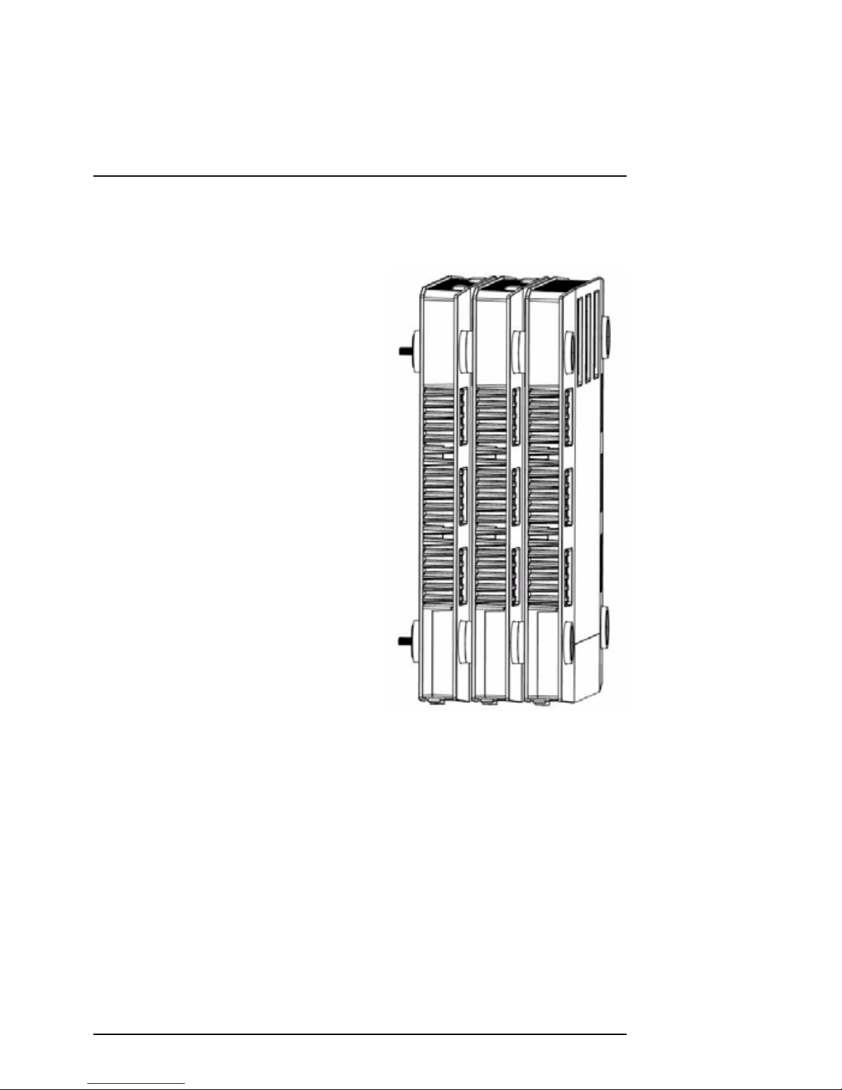
Installing 2 or 3 AC/DC Power Supply units
You can mount up to three AC/DC Power
Supply units in a vertical (recommended to use
the Wall-mount tray, heavy duty, with cablerelief bracket, order number: 406080Aopt.001) or horizontal position. When mounted
in a vertical position, with the connector panel
pointing downwards, the unit fulfills IP32 in
areas with more than 42 V and IP22 in other
areas. The mounting holes in the AC/DC Power
Supply are designed in such a way that units fit
nicely on top of each other when being
stacked.
The drawing shows the specifications of the mounting bolts needed when
installing two or three units on top of each other.
• 2-block mount: 4 x M6X100 mm DIN912 Ubrako
• 3-block mount: 4 x M6X140 mm DIN912 Unbrako
Important
To ensure adequate cooling of
the AC/DC Power Supplies an
unobstructed space of
minimum 5 cm must be
maintained around all sides
of the group of units (except
between the units and the
bottom side).
Page 24

Chapter 2: Installation
16 Installing 2 or 3 AC/DC Power Supply units
Wiring for daisy-chaining
The following drawing shows how to wire the AC/DC Power Supply units when
daisy-chaining two or three units.
To daisy-chain two or three AC/DC Power Supply units proceed as follows:
1. Connect Mains AC of unit 1 to unit 2.
2. Connect DC1 of unit 1 to DC2 of unit 2.
3. For the third unit, repeat steps 1. and 2. to connect unit 2 to unit 3.
Caution! If you need more than 3x300 W or 30 A you need
to follow special guidelines when connecting the
required AC/DC Power Supply units. Refer to
Wiring four or more AC/DC Power Supply units on
page 27 to see how to connect the AC/DC Power
Supply units to meet these requirements.
Emergency
battery
TT-6080A
Mains AC
DC1 DC2 BATTERY
TT-6080A
Mains AC
DC1
DC2
BATTERY
TT-6080A
Mains AC
DC1
DC2
BATTERY
Combined
DC Out
AC Power
Combined
DC Out
Page 25

17
Chapter 3
3333
Service and repair
Service and repair 3
The AC/DC Power Supply is designed to operate without preventive
maintenance.
Repair or repair attempts performed by unqualified personnel may limit the
warranty. The warranty on the system is defined and outlined by the
distributor that supplied the AC/DC Power Supply.
Contact for support
For support contact the distributor that supplied the AC/DC Power Supply.
For further information on warranty and service, you may also use the
Thrane & Thrane home page at www.thrane.com
Repair and servicing
The AC/DC Power Supply does not require maintenance and adjustment apart
from routine checking of its installation.
Warning! Never insert or remove a power supply while its power
switch is in the On (|) position. Make sure the power
switch is Off (O) first.
Important
In case of malfunctioning do not open the AC/DC Power Supply
but send it in for repair. For information how to proceed see
Returning units for repair on page 19.
Page 26

Chapter 3: Service and repair
18 Exchanging the fuses
Exchanging the fuses
The AC/DC Power Supply has two fuses to secure AC input and input from an
external battery.
Exchanging the AC fuse
To exchange the AC fuse, do as follows:
1. Locate the fuse, it is accessible from outside the housing. It is positioned
next to the on/off switch.
2. Turn the device that holds the fuse and extract it.
3. Take out the old fuse and insert a new one (type: 5x20 mm, 6.3 AT
4. Insert and fasten the fuse holder.
Fuse, AC input
2 fuses, battery input
Caution! If the AC fuse is blown directly after being
replaced there might be a serious fault in the
AC/DC Power Supply. Return the unit for repair.
Page 27

Chapter 3: Service and repair
Returning units for repair 19
3333
Service and repair
Exchanging the BATTERY fuses
To exchange the two BATTERY fuses, do as follows:
1. Locate the fuses for battery plus and one for battery minus. These are
accessible from outside the housing, They are is positioned to the right of
the protective lid.
2. Pull out the fuses.
3. Insert two new fuses (type: ATO Blade Fuse, 30 A)
Returning units for repair
To return equipment to Thrane & Thrane for repair this Return Material
Authorization (RMA) procedure must be followed. Failure to comply with this
procedure may cause shipping delays and additional charges.
Warranty returns
Equipment that qualifies for warranty repair can be returned to Thrane &
Thrane for repair or replacement at our discretion. The customer is charged
for the shipping costs to Thrane & Thrane, and Thrane & Thrane will pay the
shipping costs to return the repaired/replaced unit to the customer.
Non-warranty returns
Equipment that fails to work properly because of improper or negligent use,
abuse, shipping damaged or any other condition can still be returned to
Thrane & Thrane for repair or replacement at our discretion.
The customer will be notified of the cost to repair or replace the unit before
invoicing for repair or replacement. The customer is charged for the shipping
cost to and from Thrane & Thrane.
Page 28

Chapter 3: Service and repair
20 Returning units for repair
Repackaging requirements
An AC/DC Power Supply unit should be returned to Thrane & Thrane in the
original packaging. If the original packaging is not available, follow these
guidelines when repacking the unit(s):
1. Protect the connectors from physical damage and electrostatic discharge.
2. Wrap the unit in heavy paper or in bubble plastic sheets. Attach a tag with
model number, serial number and return address.
3. Use a strong shipping container, e.g. double-walled carton or similar.
4. Protect the front and rear panel with suitable material (cardboard, foam or
bubble plastic sheets) and insert a 7-10 cm layer of shock absorbing
material between all surfaces of the equipment and the sides of the
container.
5. Seal the shipping container securely.
6. Mark the shipping container FRAGILE to ensure careful handling.
Failure to do so may invalidate the warranty.
Page 29

Chapter 3: Service and repair
Returning units for repair 21
3333
Service and repair
RMA procedure
Before returning units for repair, please follow this procedure:
1. Have the following information ready before calling the Customer Service
Center:
• T&T Model number.
• Serial number (example: 00443322).
• A thorough description of the fault.
2. If you have purchased your AC/DC Power Supply from a Thrane & Thrane
distributor, contact the Customer Service Center of the distributor.
3. Describe the fault as thoroughly as possible and ask for assistance. In some
cases, the error may be resolved over the phone.
4. If the unit has to be returned for repair, request an RMA number.
5. Request replacement/loan unit if required.
6. Pack the equipment or parts to be returned in approved shipping
containers.
7. Write the RMA number on the outside of all shipping containers and ship
to the following address:
Thrane & Thrane A/S
Lundtoftegårdsvej 93 D
DK-2800 Kgs. Lyngby
Denmark
Page 30

Chapter 3: Service and repair
22 Returning units for repair
Page 31

23
Appendix A
AAAA
Technical specifications
Technical specifications A
The following tables show the electrical and environmental specifications of
the AC/DC Power Supply.
Specifications Value
Output power at 100 VAC - 240 VAC 300 W continuous
370 W peak (2 min.)
Output power at 90 VAC - 100 VAC 270 W continuous
333 W peak (2 min.)
DC output (nominal) 31.2 VDC at 0 A
29.3 VDC at 10 A
28.7 VDC at 13 A
AC input voltage 115-230 VAC nominal,
100-240 VAC operating
Alarm in case of AC power failure
IP rating in high voltage (>42 V) IP 3X
IP rating in other areas IP 2X
IP rating when mounted vertically on a wall IP X2
Operating temperature -25° to +55° C
Page 32

Appendix A: Technical specifications
24
Storage temperature -40° to +80° C
Cooling No forced cooling
required.
Survival temperature (power on) -40° to +80° C
Dimensions H: 46.5 mm, L: 354 mm,
W: 265 mm
Weight Approx. 3.7 kg
Compass safe distance 30 cm
Specifications Value
Page 33

25
Appendix B
BBBB
Wall-mount tray (option)
Wall-mount tray (option) B
A Wall-mount tray, heavy duty, with cable-relief bracket is available and can be
ordered (order number: 406080A-opt.001).
Up to 3 AC/DC Power Supply units can be mounted on this tray.
Page 34

Appendix B: Wall-mount tray (option)
26
Dimensions and weight
Dimensions
Weight
The Wall-mount tray, heavy duty, weighs 2.5 kg.
Page 35

27
Appendix C
CCCC
Special installation
Special installation C
If you need more than 3x300 W or 30 A you can connect more than 3 AC/DC
Power Supply units.
Wiring four or more AC/DC Power Supply units
Important
You must connect the units as shown in the drawing. This is to
make sure that a single connector is never overloaded with
more than 30 A.
Emergency
Battery
TT-6080A TT-6080A TT-6080A TT-6080A
Fuse
+
-
UserUser
Cable lengths t o achieve cable resistance higher than 100 m:
cross section: 2.5 mm2 > 2 m
cross section: 6 mm2 > 25 m
+
-
The cable resistance must
be > 100 m
DC
Page 36

Appendix C: Special installation
28
Page 37

29
Appendix D
DDDD
Declaration of conformity
Declaration of conformity D
CE (LVD & EMC)
The AC/DC Power Supply is CE certified (LVD & EMC directives) as stated in the
“Declaration of Conformity with LVD and EMC Directives”, enclosed in copy on
the next page.
Page 38

Appendix D: Declaration of conformity
30
Page 39

31
Glossary
EEE
Glossary
Glossary E
A
AC Alternating Current
C
CE Conformité Européenne, European conformity in French.
D
DC Direct Current
E
EMC Electromagnetic Compatibility
I
IEC International Electrotechnical Commission is an international
standards organization that prepares and publishes International
Standards for all electrical, electronic and related technologies.
IP International Protection Rating, sometimes also interpreted as
Ingress Protection Rating, consists of the letters IP followed by
two digits and an optional letter. It classifies the degrees of
protection provided against the intrusion of solid objects
(including body parts like hands and fingers), dust, accidental
contact, and water in electrical enclosures.
L
LVD Low Voltage Directive
Page 40

Glossary
32
Page 41

33
Index
FFF
Index
Index F
A
AC alarm output, 14
AC input, 10
accessories, 5
applications, 4
approval
certificate, 29
maritime, 2
B
battery
connector, 13
input, 13
block diagram, 3
C
cable-relief bracket, 5, 8
CE certification, 29
CE compliance, 29
combining
4 or more units, 25, 27
up to 3 units, 4
Compass safe distance, 24
conformity, 29
connector
AC alarm output, 14
AC input, 10
battery, 13
DC1, 11
DC2, 12
overview, 6
cooling requirements
several units, 15
single unit, 6
D
daisy-chaining
setup for 3 units, 16
wiring, 16
DC input, 12
DC output, 11, 12
declaration of conformity, 29
document number
this manual, i
F
features, 2
fuse, 5
AC input, 10
AC, exchanging, 18
battery, 13
battery, exchanging, 19
I
IEC 60945, 2
input
AC, 2
battery, 13
DC for daisy-chaining, 12
installation
2 or 3 units, 15
4 units or more, 25, 27
cable-relief bracket, 8
IP rating, 1, 2, 23
L
lid
remove, 9
Page 42

Index
34
M
manual
document number, i
mounting bolts, 5
1 unit, 7
2-Block mount, 15
3-Block mount, 15
O
order number
accessories, 5
mountings bolts, 5
wall mount tray, 5
outline, 7
output power, 2
P
peak output power, 2
power
output, 2
protective lid
remove, 9
removing, 9
R
remove
protective lid, 9
repackaging, 20
repair, 17
return
non-warranty, 19
warranty, 19
returning units for repair, 19
S
safety summary, iii
servicing, 17
several units
connecting, 16
installing, 15
specifications, 23
spring terminal connector, 9
stacking several units, 4
support
contact, 17
T
technical specifications, 23
tray for wall mount, 25
U
unpacking, 5
W
wall mount tray, 25
order number, 5
warranty return, 19
Page 43

Page 44

98-129099-C
Thrane & Thrane A/S • info@thrane.com • www.thrane.com
 Loading...