

Page 1
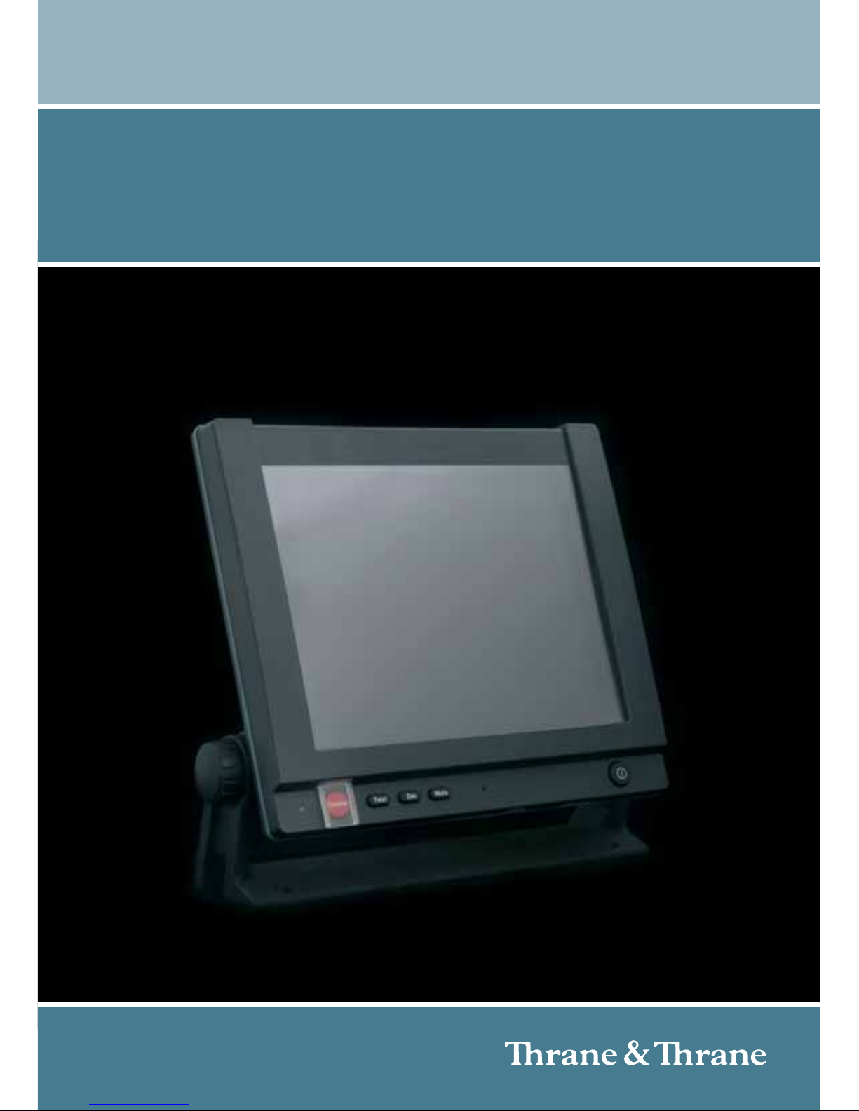
TT-6006A and TT-6007A
Message terminal
INSTALLATION MANUAL
Page 2

Page 3

TT-6006A and TT-6007A
Message Terminal
Installation manual
Document number: 98-130088-B
Release date: March 16, 2010
Page 4

Disclaimer
Any responsibility or liability for loss or damage in connection with the use of this
product and the accompanying documentation is disclaimed by Thrane & Thrane. The
information in this manual is provided for information purposes only, is subject to
change without notice and may contain errors or inaccuracies. Manuals issued by
Thrane & Thrane are periodically revised and updated. Anyone relying on this
information should acquire the most current version e.g. from http://www.thrane.com or
from the distributor. Thrane & Thrane is not responsible for the content or accuracy of
any translations or reproductions, in whole or in part, of this manual from any other
source.
Copyright
© 2010 Thrane & Thrane A/S. All rights reserved.
Trademark Acknowledgements
• Thrane & Thrane is a registered trademark of Thrane & Thrane A/S in the European
Union and the United States.
• Inmarsat is a registered trademark of the International Maritime Satellite
Organisation (IMSO) and is licensed by IMSO to Inmarsat Limited and Inmarsat
Ventures plc.
• Other product and company names mentioned in this manual may be trademarks or
trade names of their respective owners.
Page 5

iii
Safety summary 1
The following general safety precautions must be observed during all
phases of operation, service and repair of this equipment. Failure to comply
with these precautions or with specific warnings elsewhere in this manual
violates safety standards of design, manufacture and intended use of the
equipment. Thrane & Thrane assumes no liability for the customer's failure
to comply with these requirements.
GROUND THE EQUIPMENT
To minimise shock hazard, the equipment chassis and cabinet must be
connected to an electrical ground and the cable instructions must be
followed.
DO NOT OPERATE IN AN EXPLOSIVE ATMOSPHERE
Do not operate the equipment in the presence of flammable gases or fumes.
Operation of any electrical equipment in such an environment constitutes a
definite safety hazard.
KEEP AWAY FROM LIVE CIRCUITS
Operating personnel must not remove equipment covers. Component
replacement and internal adjustment must be made by qualified
maintenance personnel.
DO NOT SUBSTITUTE PARTS OR MODIFY EQUIPMENT
Because of the danger of introducing additional hazards, do not substitute
parts or perform any unauthorized modification to the equipment.
COMPASS SAFE DISTANCE
Minimum safety distance: 1 m from the Message Terminal
Failure to comply with the rules above will void the warranty!
Page 6

iv
About the manual 2
Intended readers
This manual is an installation manual for the Message Terminal.
The manual is intended for installers of the Message Terminal and
service personnel. Personnel installing or servicing the system
must be properly trained and authorized by Thrane & Thrane. It is
important that you observe all safety requirements listed in the
beginning of this manual, and install the system according to the
guidelines in this manual.
Manual overview
Note that this manual does not cover how to use the system. For
information on usage refer to the user manual for the system in
which you are using the Message Terminal.
This manual has the following chapters:
• Installation gives an introduction to the two types of Message
Terminal, explains how to mount the units and gives guidelines
for storage and repacking for shipment.
• Connectors and controls shows outline and pin-out for all
connectors on the Message Terminal and explains the
functions of the buttons in the front panel.
Page 7

v
Table of Contents
Chapter 1 Installation
In this chapter .................................................................... 1
The Message Terminal .......................................................2
Initial inspection ................................................................4
Installation .........................................................................5
Storage ..............................................................................7
Repacking for shipment .....................................................7
Chapter 2 Connectors and controls
In this chapter ....................................................................9
Connectors ....................................................................... 10
Buttons in the front panel ................................................23
App. A Specifications
In this chapter ..................................................................25
General specifications ......................................................25
App. B Mechanical outlines
In this chapter ..................................................................27
Outline drawing: Bottom, front and top ............................28
Outline drawing: Rear ......................................................29
Outline drawing: Side and perspective view .....................30
Outline drawing: Flush mount plate ..................................31
Outline drawing: Cable Relief Plate ..................................32
Page 8

Table of Contents
vi
Glossary .........................................................................................33
Index .........................................................................................37
Page 9

1
Chapter 1
1111
Installation
Installation 1
In this chapter
This chapter provides a short description of the two types of Message
Terminal, including descriptions of:
• The Message Terminal
• Initial inspection
• Installation
• Storage and
• Repacking for shipment
Page 10
Chapter 1: Installation
2The Message Terminal
The Message Terminal
GMDSS or general purpose terminal
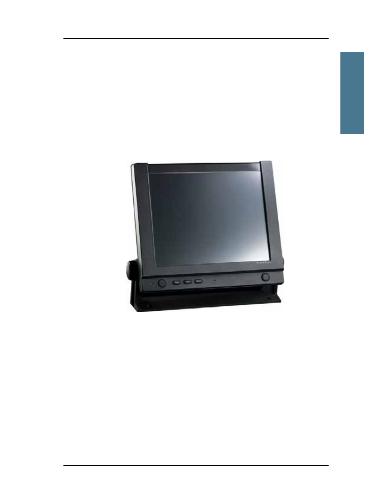
There are two variants of the Message Terminal: The TT-6006A and the
TT-6007A. The only visible difference is the Distress button on the TT-6006A,
which is a GMDSS approved terminal. The next sections describe the two
terminals.
TT-6006A
The TT-6006A Message Terminal is a maritime terminal for use in GMDSS
installations, providing several types of interfaces for connection to external
equipment, such as a Mini-C transceiver, MF/HF Radio Telex applications and
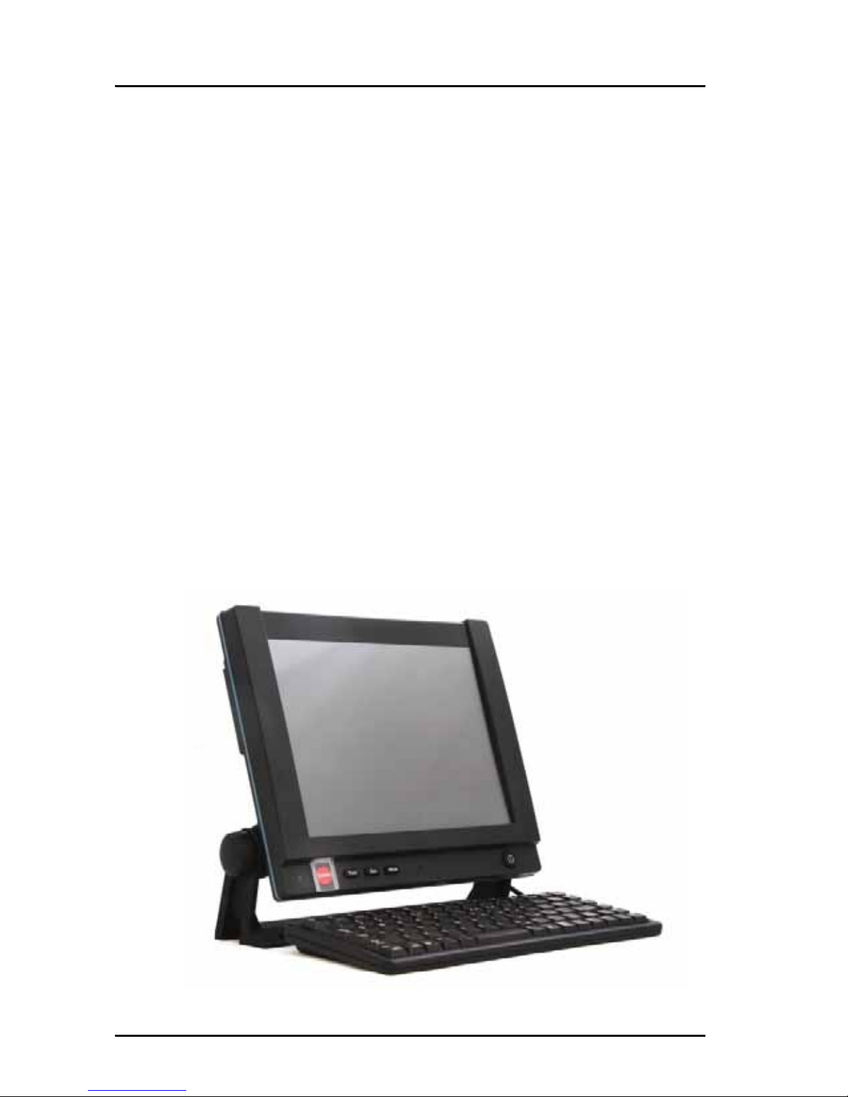
an Alarm panel. The Message Terminal has a touch-screen for operating the
terminal. However, in GMDSS installations a keyboard is mandatory. A
suitable keyboard is available from Thrane & Thrane.
Page 11
Chapter 1: Installation
The Message Terminal 3
1111
Installation
TT-6007A
The TT-6007A Message Terminal is a general purpose maritime terminal, e.g.
for fishery e-log using third party software. It provides several types of
interfaces for connection to external equipment, such as a Mini-C transceiver
or BGAN terminal, an ethernet switch and a printer. The Message Terminal
has a touch-screen for operating the terminal. You may also connect an
external keyboard and mouse/trackball.
Page 12
Chapter 1: Installation
4Initial inspection
Initial inspection
Inspect the shipping carton immediately upon receipt for evidence of
mishandling during transport. If the shipping carton is severely damaged or
water stained, request that the carrier's agent be present when opening the
carton. Save the carton packing material for future use.
Check that the contents of the shipment are according to the enclosed packing
list. If the contents are incomplete, if there is mechanical damage or defect, or
if the Message Terminal does not work properly, notify your dealer.
After unpacking the Message Terminal, inspect it thoroughly for hidden
damage and loose components or fittings.
Warning! To avoid electrical shock, do not apply power to the
Message Terminal if there is any sign of shipping damage
to any part of the front or rear panel or the outer cover.
Read the safety summary at the front of this manual before
installing or operating the Message Terminal.
Page 13
Chapter 1: Installation
Installation 5
1111
Installation
Installation
Cable requirements
All cables attached to the Message Terminal must be shielded. Every shield
should have a low impedance connection to an electrical ground.
For information on connectors, see Connectors on page 10.
Before using the Message Terminal for the first time, check that all cables are
correctly wired and fastened.
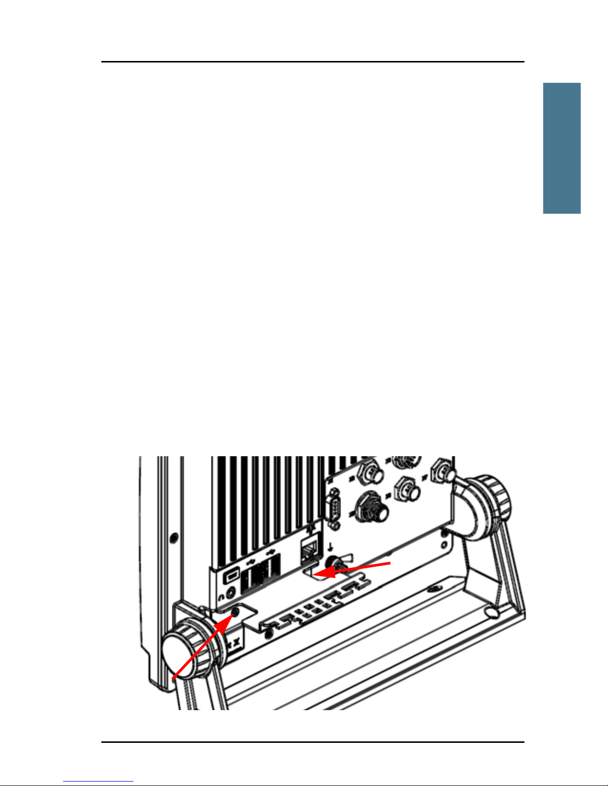
Mounting
Mounting the cable relief plate
Before installing the Message Terminal, mount the cable relief plate on the
connector panel as shown below using the 2 screws included with the cable
relief plate. For outline drawings of the Cable Relief Plate, see Outline
drawing: Cable Relief Plate on page 32.
Page 14
Chapter 1: Installation
6 Installation
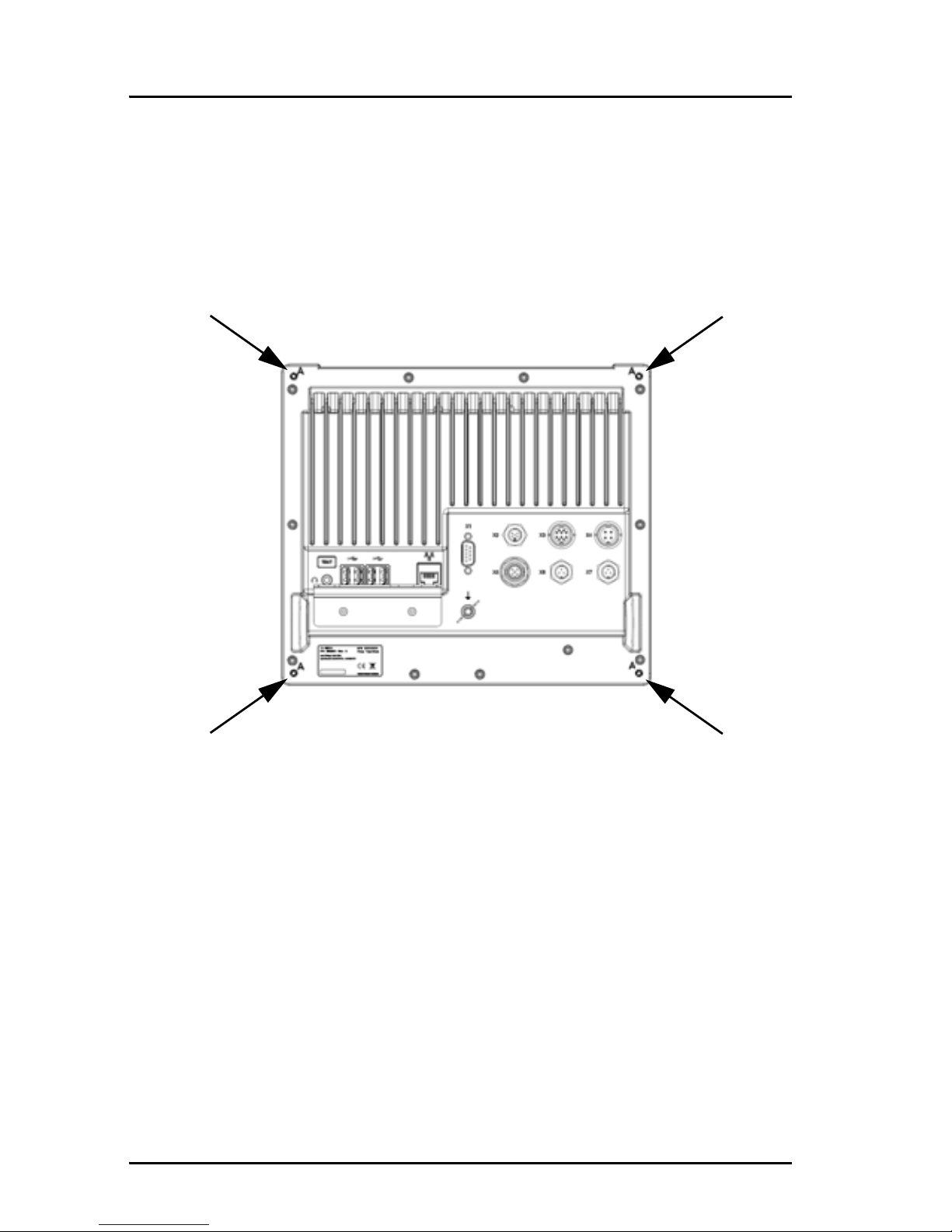
Flush mount
You can flush mount the Message Terminal in a console by using the 4 screw
holes (A) on the back of the terminal. The holes are M4 x 10 mm. For a
drawing of the Flush-mount plate with panel cut-out and mounting holes, see
Outline drawing: Flush mount plate on page 31.
Wall or desktop mounting
You can mount the Message Terminal on a horizontal surface or a vertical
surface using the optional mounting bracket. Do as follows:
1. Use the four holes in the mounting bracket to fasten the terminal to the
mounting surface. Screws are included with the mounting bracket.
2. Adjust the angle in steps of 7.5° by loosening the hand wheels slightly and
moving the Message Terminal into the wanted position. Remember to
tighten the hand wheels again.
Please refer to chapter B, Mechanical outlines, describing the detailed
mechanical outlines of the Message Terminal and mounting bracket.
Page 15

Chapter 1: Installation
Storage 7
1111
Installation
Storage
The Message Terminal may be stored or shipped in temperatures between
-40° C and +80° C. Protect the Message Terminal from extreme temperature
variation which can cause condensation.
We recommend that you unpack the Message Terminal immediately on
delivery.
Repacking for shipment
The shipping carton has been carefully designed to protect the Message
Terminal and its accessories during shipment. This carton and its associated
packing material should be used when repacking for shipment. Attach a tag
indicating the type of service required, return address, model number and full
serial number. Mark the carton FRAGILE to ensure careful handling.
If the original shipping carton is not available, the following general
instructions should be used for repacking with commercially available
material.
1. Wrap the Message Terminal in heavy paper or plastic. Attach a tag
indicating the type of service required, return address, model number and
full serial number.
2. Use a strong shipping container, e.g. a double walled carton of 160 kg test
material.
3. Protect the front- and rear panel with cardboard and insert a 7 cm to 10 cm
layer of shock-absorbing material between all surfaces of the equipment
and the sides of the container.
4. Seal the shipping container securely.
5. Mark the shipping container FRAGILE to ensure careful handling.
Page 16

Chapter 1: Installation
8 Repacking for shipment
Page 17

9
Chapter 2
2222
Connectors and controls
Connectors and controls 2
In this chapter
This chapter provides a description of all connectors and controls on the
Message Terminal. It has the following sections:
• Connectors
• Buttons in the front panel
Page 18

Chapter 2: Connectors and controls
10 Connectors
Connectors
Overview
The drawing below shows the connectors on the Message Terminal.
4 x USB Ethernet
Ground
RS-232
DC Power
input
USB
CAN-bus
NMEA 183
2 x NMEA 183 Listener
Talker
Memory card
holder SDHC
Handset or
Hand microphone
Stereo audio
output
Page 19

Chapter 2: Connectors and controls
Connectors 11
2222
Connectors and controls
USB interface
Overview
There are four USB Host interface ports (USB Type A) in the rear panel of the
Message Terminal and one at the bottom of the front panel.
The applications for the USB ports are as follows:
• Front panel USB port: Temporary connection of mass storage devices
• Rear panel: One for printer, one for keyboard and two for general use.
Page 20

Chapter 2: Connectors and controls
12 Connectors
Pin-out
The USB connectors are USB Type A. The figure and table below show the
connector outline, wire colors and pin assignments.
Pin number Pin function Wire color
15VRed
2 D- White
3D+Green
4 GND Black
USB Type A socket
Page 21

Chapter 2: Connectors and controls
Connectors 13
2222
Connectors and controls
Ethernet interface
Overview
There is one Ethernet (10/100 MB) connector on the rear panel of the Message
Terminal. The Ethernet interface can be used for communicating with
connected equipment, such as a TT-6081A power supply or an alarm panel.
Pin-out
The figure and table below show the connector outline, pin assignments and
wire color.
Pin number Pin function Wire color
1 Tx+ white/orange
2 Tx- orange
3 Rx+ white/green
4 Not connected blue
5 Not connected white/blue
6 Rx- green
7 Not connected white/brown
8 Not connected brown
RJ-45 female
Page 22

Chapter 2: Connectors and controls
14 Connectors
RS-232 interface (X1)
overview
There is one RS-232 DTE connector on the rear panel of the terminal.
Pin-out
The figure and table below show the connector outline and pin assignments.
Pin number Pin function
1 Not Connected
2 RxD (Receive Data) Input
3 TxD (Transmit Data) output
4 DTR (Data Terminal Ready) output
5GND
6 DSR (Data Set Ready) Input
7 RTS (Request To Send) output
8 CTS (Clear To Send) Input
9 Not Connected
D-Sub, 9 pin male
Page 23

Chapter 2: Connectors and controls
Connectors 15
2222
Connectors and controls
NMEA 0183 compatible Talker interface (X2)
Overview
The NMEA 0183 compatible Talker interface complies to IEC 61162-1 and IEC
61162-2. You can select between two speeds: 4800 or 38400 Baud.
Pin-out
The figure and table below show the connector outline and pin assignments.
Note
The NMEA 0183 compatible Talker connector is a custom connector;
a matching cable with connector is available from Thrane & Thrane.
The cable is 1.80 m long and the part number is 37-131222-A.
Pin number Pin function
1TA-
2 TB+
3GND
4 General purpose input
5 General purpose input
Mini Panel lock, 5 pin male
Page 24

Chapter 2: Connectors and controls
16 Connectors
Accessory interface (X3)
Overview
The Accessory interface connects to e.g. the TT-6201 Handset and the TT-6202
Hand microphone.
Pin-out
The figure and table below show the connector outline and pin assignments.
Pin number Pin function
1NC
2 NC
3NC
4 NC
5MIC+
6 EARPIECE
7HOOK/PTT
8 12 V DC output for handset
9GND
10 GND
Panel lock, 10 pin male
Page 25

Chapter 2: Connectors and controls
Connectors 17
2222
Connectors and controls
DC Power input (X4)
Overview
The DC Power input connects to a DC supply with 12 to 24 V DC nominal (10.8 to
32 V DC). The interface also has a “remote on/off” function and an “on/off
control” output.
Pin-out
The figure and table below show the connector outline, pin assignments and
wire color in the power cable delivered with the Message Terminal.
Note
The Power connector is a custom connector; a matching cable with
connector is included in the delivery.
Pin
number
Pin function
Wire color in
power cable
1 DC+ (10.8 - 32 V DC) Red
2 DC- (0 V DC) Black
3ON_IN
(see next page)
White
4 ON_OUT
(see next page)
Blue
Panel lock, 4 pin male
Page 26

Chapter 2: Connectors and controls
18 Connectors
Connecting DC power
Connect DC+ (red wire) to DC out + from your DC supply.
Connect DC- (black wire) to DC out - from your DC supply.
Do not connect the white wire nor the blue wire in the power cable, unless you
want to use the Remote on/off function or the On/off control function.
Connecting Remote on/off (ON_IN)
With the Remote on/off function you can switch the Message Terminal on and
off from a remote location, without using the on/off button on the terminal. To
connect the Remote on/off function in the Message Terminal, do as follows:
1. Connect DC+ and DC- as described in the previous section.
2. Connect a switch to the white wir e in the power cable (pin 3, ON_IN, in the
Power connector.)
3. Connect the other side of the switch to the black wire in the power cable
(DC- (0 V DC) in the Power connector), with a resistance below 10 k.
To switch on the Message Terminal, close the switch. When the switch is
closed, Pin 3 in the Power connector is connected to DC-.
Connecting On/off control (ON_OUT)
You can use pin 4 in the Power connector (blue wire) to switch other units on
and off when the Message Terminal is switched on and off. How to connect
this pin depends on the units you connect.
The function of pin 4 is as follows:
• Message Terminal off: Pin 4 is high (DC+ i.e. between 10.8 V DC and
32 V DC).
• Message Terminal on: Pin 4 is low (DC- from the power supply, with 10 k
serial resistance)
Note
When the remote switch is closed (the Message Terminal is switched
on), you cannot use the Power button on the Message Terminal.
Page 27

Chapter 2: Connectors and controls
Connectors 19
2222
Connectors and controls
CAN-bus interface (X5)
Overview
The CAN-bus interface in the Message Terminal supports bidirectional
communication.
Pin-out
The figure and table below show the connector outline, pin assignments and
standard wire colors.
Note
The CAN-bus connector is a custom connector; a matching cable
with connector is available from Thrane & Thrane.
Pin number Pin function Wire color
1 Not connected None
2 CAN_S Red
3CAN_CBlack
4 CAN_H White
5CAN_LBlue
M12 Panel screw connector
5 pin male
Page 28

Chapter 2: Connectors and controls
20 Connectors
NMEA 0183 compatible Listener interface (X6 and X7)
Overview
The Message Terminal has two NMEA 0183 compatible Listener interfaces, one
high speed (X6: 4800/38400 Baud) and one low speed (X7: 4800 Baud).
Pin-out
The figure and table below show the connector outline and pin assignments.
Note
The NMEA 0183 compatible Listener connector is a custom
connector; a matching cable with connector is available from Thrane
& Thrane. The cable is 1.80 m long and the part number is
37-131223-A.
X7: 4800 Baud
X6: 4800/38400 Baud
Pin number Pin function
1LA-
2 LB+
3GND
Mini panel lock, 3 pin male
Page 29

Chapter 2: Connectors and controls
Connectors 21
2222
Connectors and controls
Memory card holder, SDHC
Overview
The Message Terminal has a slot where you can insert a memory card of the
type SDHC (Secure Digital High Capacity). The memory card slot is located at
the bottom of the terminal next to the front USB connector.
Page 30

Chapter 2: Connectors and controls
22 Connectors
Ground st ud
The ground stud is located in the connector panel and is used to connect a
ground wire for grounding the Message Terminal.
To connect the Message Terminal to ship ground, do as follows:
1. Connect a ground cable of > 1 m length and > 4 mm
2
cross section to the
Ground stud and fasten it with the wing nut.
2. Connect the other end of the cable to ship ground.
Important
You must connect the Ground stud to ship ground.
Page 31

Chapter 2: Connectors and controls
Buttons in the front panel 23
2222
Connectors and controls
Buttons in the front panel
Overview
The drawing below shows the buttons on the Message Terminal.
Note
Only TT-6006A has a Distress button. It is not available on TT-6007A.
Distress
button
Test
button
Dim
button
Mute
button
Power
button
Page 32

Chapter 2: Connectors and controls
24 Buttons in the front panel
Functions of the buttons
The buttons in the front panel have the following functions:
Control Function
Distress (only
on TT-6006A)
The Distress button on the TT-6006A Message Terminal
is used in safety systems to send a distress message
through a connected transceiver. Refer to the manual for
your system for information on the function.
Test The Test button is used to test the lights and sound in
the buttons on the Message Terminal.
Dim The Dim button is used to dim the light in the Message
Terminal.
Push and hold to dim more/less. Each new push
changes direction between more and less.
Mute The mute button is used to mute the Message Terminal
and, in some applications, connected equipment. Refer
to the manual for your system for details.
Power Without remote on/off:
To switch on: Push the button
To switch off: Push and hold for 2 seconds
If the Message Terminal cannot switch off normally (e.g.
corrupt software): Push and hold for 10 seconds
With remote on/off:
To switch on and off: The Power button cannot be used
normally; use the remote on/off switch to switch the
Message Terminal on and off.
To restart the terminal: Push and hold for 2 seconds
Corrupt software: Push and hold for 10 seconds to restart
Page 33

25
Appendix A
AAAA
Specifications
Specifications A
In this chapter
This chapter provides general specifications for the Message Terminal.
General specifications
Item Specifications
CPU
• Intel atom based CPU
• SSD (Solid State Drive) for operating system (GNU/Linux or
Windows XP embedded), application software and data
storage.
Additional
storage media
• SD card slot for user data storage (accepts SDHC)
• USB Host interface connector for mass storage devices
Display 10.4” Touch screen, 800 x 600 pixels TFT, LED backlight
Keyboard i/f USB
Printer port USB
Power 10.8 to 32 V DC, with “remote on/off” input and “on/off control”
output
Power
Consumption
Max. 20 W, typical 12 W
Page 34

Appendix A: Specifications
26 General specifications
Interfaces
• 4 USB Host interface ports - one for printer, one for keyboard
and 2 for general use (all up to 480 MB).
• 1 USB port (front) for external storage (up to 12 MB).
• Ethernet (10/100Mbit), RJ45
•RS232, DB9 male
• Isolated CAN-bus interface
• NMEA 0183 compatible talker, ref. to chassis (secondary gnd)
• NMEA 0183 compatible listener, isolated, 4800 Baud max.
• NMEA 0183 compatible listener, isolated, 4800/38400 Baud
max
• Accessory interface for e.g. handset or hand microphone
• Stereo audio output, e.g. for loudspeakers
• One digital input pin for simple active/inactive detection.
Environmental
• Meets or exceeds all Inmarsat specifications for the
Inmarsat-C Network for SOLAS with distress call functions.
(CN114 and IEC 945 requirements).
• Meets CE-marking requirements.
• TT-6006A is Wheelmark approved.
• IP protection class: IP30 on the rear section, IP33 on the front
surface.
Ambient
Temperature
-25°C to 55°C operating -40°C to 80°C storage.
Compass safe
distance
1m
Dimensions H
x W x D
• 233.9 x 268.8 x 59.9 mm without bracket
• 258.8 x 299.6 x 92.3 mm with bracket at vertical position
Weight 2.0 kg without mounting bracket, 2.2 kg with bracket
Item Specifications
Page 35

27
Appendix B
BBBB
Mechanical outlines
Mechanical outlines B
In this chapter
This chapter shows outline drawings with the dimensions and weight of the
Message Terminal.
Page 36

Appendix B: Mechanical outlines
28 Outline drawing: Bottom, front and top
Outline drawing: Bottom, front and top
227
53
268.8
258.8
299.6
92.3
112.8
273
70.9
4
x
ø
4
.
2
1
0
.
4
”
NOTE: Distress button only on TT-6006A
Page 37

Appendix B: Mechanical outlines
Outline drawing: Rear 29
BBBB
Mechanical outlines
Outline drawing: Rear
251.2
216.3
Weight: 2.0 kg without mounting bracket and wheel knobs
All units are in millimeters
A: 4 pcs. M4 x 10
Total weight: 2.2 kg
Page 38

Appendix B: Mechanical outlines
30 Outline drawing: Side and perspective view
Outline drawing: Side and perspectiv e view
59.9
70.3
18.5
24.9
233.9
Page 39

Appendix B: Mechanical outlines
Outline drawing: Flush mount plate 31
BBBB
Mechanical outlines
Outline drawing: Flush mount plate
(2)
216.3
4.4
ø
4
.
4
251.2
260
205
5.65
4.4
ø
4
.
4
ø
4
.
4
ø
4
.
4
5.65
All units are in millimeters
Page 40

Appendix B: Mechanical outlines
32 Outline drawing: Cable Relief Plate
Outline drawing: Cable Relief Plate
93
67.8
30.3
Page 41

33
Glossary
CCCC
Glossary
Glossary C
B
BGAN Broadband Global Area Network. A satellite network based on
geostationary satellites, delivering data rates of up to 492 kbps to
virtually any part of the earth, with full UMTS (3G) compatibility.
C
CAN Controller-Area Network. A vehicle bus standard designed to
allow microcontrollers and devices to communicate with each
other within a vehicle without a host computer. CAN is a message
based protocol, designed specifically for automotive applications
but now also used in other areas such as industrial automation
and medical equipment.
CPU Central Processing Unit, also known as a processor. The portion of
a computer system that carries out the instructions of a computer
program, and is the primary element carrying out the computer’s
functions.
D
DTE Data Terminal Equipment. Includes Computers, Serial Printers,
PLC’s, Video Cameras, Video Recorders, Video Editors, and most
devices which are not used to extend communications.
G
GMDSS Global Maritime Distress Safety System. GMDSS consists of
several systems, some of which are new, but many of which have
been in operation for many years. The system is intended to
perform the following functions: alerting (including position
determination of the unit in distress), search and rescue
coordination, locating (homing), maritime safety information
broadcasts, general communications, and bridge-to-bridge
communications.
Page 42

Glossary
34
GNU A computer operating system composed entirely of free software.
Its name is a recursive acronym for “GNU’s Not Unix!” This name
was chosen because GNU’s design is Unix-like, but differs from
Unix by being free software and containing no Unix code.
H
HF High Frequency. Radio frequencies between 3 and 30 MHz. Used
for direct, long-distance (often inter-continental)
communications.
I
IEC International Electrotechnical Commission. The international
standards and conformity assessment body for all fields of
electrotechnology.
IMSO International Maritime Satellite Organisation
IP Ingress Protection. EN 60529 outlines an international
classification system for the sealing effectiveness of enclosures of
electrical equipment against the intrusion into the equipment of
foreign bodies (i.e. tools, dust, fingers) and moisture. This
classification system uses the letters "IP" ("Ingress Protection")
followed by two or three digits. (A third digit is sometimes used.
An "x" is used for one of the digits if there is only one class of
protection; e.g. IPX4 which addresses moisture resistance only.)
L
LED Light Emitting Diode
Page 43

Glossary
35
CCCC
Glossary
M
MF Medium Frequency. Radio frequencies (RF) in the range of 300
kHz to 3 MHz. Navtex, which is part of the current Global Maritime
Distress Safety System occupies 518 kHz and 490 kHz for important
digital text broadcasts.
N
NMEA National Marine Electronics Association (standard). A combined
electrical and data specification for communication between
marine electronic devices such as echo sounder, sonars,
anemometer (wind speed and direction), gyrocompass, autopilot,
GPS receivers and many other types of instruments. It has been
defined by, and is controlled by, the U.S.-based National Marine
Electronics Association.
S
SD Secure Digital. A non-volatile memory card format developed by
Panasonic, SanDisk, and Toshiba for use in portable devices.
Currently it is widely used in digital cameras, digital camcorders,
handheld computers, netbook computers, PDAs, media players,
mobile phones, GPS receivers, and video games.
SDHC Secure Digital High Capacity. An extension of the SD standard
which increases card’s storage capacity up to 32 GB. SDHC cards
share the same physical and electrical form factor as older (SD 1.x)
cards, allowing SDHC-devices to support both newer SDHC cards
and older SD-cards.
SOLAS (International Convention for the) Safety Of Life At Sea. Generally
regarded as the most important of all international treaties
concerning the safety of merchant ships.
SSD Solid-State Drive. A data storage device that uses solid-state
memory to store persistent data. An SSD emulates a hard disk
drive interface, thus easily replacing it in most applications.
Page 44

Glossary
36
T
TFT Thin Film Transistor. A thin film transistor liquid crystal display
(TFT-LCD) is a variant of liquid crystal display (LCD) which uses
thin-film transistor (TFT) technology to improve image quality
(e.g., addressability, contrast).
U
USB Universal Serial Bus. A specification to establish communication
between devices and a host controller (usually personal
computers). USB is intended to replace many varieties of serial
and parallel ports. USB can connect computer peripherals such as
mice, keyboards, digital cameras, printers, personal media
players, flash drives, and external hard drives.
Page 45

37
Index
DDDD
Index
Index D
A
Accessory connector, 16
B
buttons in front panel, 23
Dim, 24
Distress, 24
Mute, 24
Power, 24
Test, 24
C
cable relief
mounting, 5
outline drawing, 32
cable requirements, 5
CAN-bus connector, 19
connectors
Accessory, 16
CAN-bus, 19
DC power input, 17
Ethernet, 13
hand microphone, 16
handset, 16
NMEA 0183 compatible Listener, 20
NMEA 0183 compatible Talker, 15
overview, 10
RS-232, 14
USB, 11
controls, 23
D
DC power input connector, 17
desktop mounting, 6
Dim button, 24
Distress button, 24
document number
this manual, i
drawings
outline, 27
E
Ethernet connector, 13
F
flush mount, 6
front panel buttons, 23
G
GMDSS approved Message Terminal, 2
ground stud, 22
grounding the Message Terminal, 22
H
hand microphone connector, 16
handset connector, 16
I
initial inspection, 4
installation, 5
Page 46

Index
38
M
manual
document number, i
mechanical drawings, 27
memory card insert, 21
Message Terminal
for general use, 3
for safety use, 2
types of, 2
mounting
cable relief plate, 5
flush mount, 6
on wall or desktop, 6
Mute button, 24
N
NMEA 0183 Listener connector, 20
NMEA 0183 Talker connector, 15
O
outline drawings, 27
P
Power button, 24
power input connector, 17
R
repacking for shipment, 7
returning units, 7
RS-232 connector, 14
S
safety summary, iii
SDHC memory card, 21
specifications, 25
storage, 7
T
Test button, 24
TT-6006A description, 2
TT-6007A description, 3
types of Message Terminal, 2
U
unpacking, 4
USB connectors, 11
W
wall mounting, 6
Page 47

Page 48

98-130088-B
Thrane & Thrane A/S • info@thrane.com • www.thrane.com
 Loading...