

Page 1

USER MANUAL
EXPLORER 700
Thrane & Thrane A/S • info@thrane.com • www.thrane.com
Page 2

98-122988-B ii
TT-3720A EXPLORER™ 700
Document number: 98-122988-B
Release date: 19 June 2006
Information in this document is subject to change without notice and does not represent a commitment on
the part of Thrane & Thrane A/S.
Copyright
© 2006 Thrane & Thrane A/S. All rights reserved.
Trademark Acknowledgements
• EXPLORER is a trademark of Thrane & Thrane A/S.
• Bluetooth is a registered trademark of Bluetooth SIG.
• Windows and Outlook are registered trademarks of Microsoft Corporation in the United States and other
countries.
• Inmarsat is a registered trademark of the International Maritime Satellite Organisation (IMSO) and is
licensed by IMSO to Inmarsat Limited and Inmarsat Ventures plc.
• Inmarsat’s product names are either trademarks or registered trademarks of Inmarsat.
• Other product and company names mentioned in this manual may be trademarks or trade names of their
respective owners.
Company Addresses
www.thrane.com
Denmark Denmark
Thrane & Thrane A/S
Lundtoftegårdsvej 93 D
DK-2800 Kgs. Lyngby
Denmark
T: +45 39 55 88 00
F: +45 39 55 88 88
Thrane & Thrane Aalborg A/S
Porsvej 2
DK-9200 Aalborg SV
Denmark
T: +45 39 55 88 00
F: +45 96 34 61 01
USA China
Thrane & Thrane, Inc.
509 Viking Drive, Suites K, L and M
Virginia Beach, VA 23452
USA
T: +1 (757) 747-2341
F: +1 (757) 463-9581
Thrane & Thrane Shanghai
Representative Office
28J Pufa Tower
588 Pudong Rd(S), Pu Dong
200120 Shanghai
P. R. China
T: +86 21 68 87 87 80
F: +86 21 68 87 71 12
Page 3
98-122988-B iii
Safety Summary 1
The following general safety precautions must be observed during all phases of
operation, service and repair of this equipment.
Failure to comply with these precautions or with specific warnings elsewhere in this
manual violates safety standards of design, manufacture and intended use of the
equipment. Thrane & Thrane A/S assume no liability for the customer's failure to
comply with these requirements.
Do Not Operate in an Explosive Atmosphere
Do not operate the equipment in the presence of flammable gases or fumes.
Operation of any electrical equipment in such an environment constitutes a definite
safety hazard.
Keep Away from Live Circuits
Operating personnel must not remove equipment covers. Component replacement
and internal adjustment must be made by qualified maintenance personnel. Do not
replace components with the power cable connected. Under certain conditions,
dangerous voltages may exist even with the power cable removed. To avoid injuries,
always disconnect power and discharge circuits before touching them.
Do Not Service Alone
Do not attempt internal service or adjustments unless another person, capable of
rendering first aid resuscitation, is present.
Do Not Substitute Parts or Modify Equipment
Because of the danger of introducing additional hazards, do not substitute parts or
perform any unauthorized modification to the equipment.
Keep Away from Antenna Front
This device emits radio frequency energy when switched on.
To avoid injury, keep a minimum safety distance of 1 m from
the antenna front when the EXPLORER™ 700 is on.
For information on the safety distance from the transceiver,
see the FCC Radiation Exposure statement on the next page.
Only Use Approved Batteries from Thrane & Thrane
Use of non approved batteries may result in explosion, fire, electrical shock or injury.
Observe Marked Areas
Under extreme heat conditions do not touch areas of the
EXPLORER™ 700 that are marked with this symbol, as it may
result in injury.
Page 4

Antenna Safety Instructions
98-122988-B iv
FCC Radiation Exposure statement
Transceiver Unit (when separated from the Antenna Unit):
This equipment complies with FCC radiation exposure limits for an uncontrolled environment. This equipment
should be installed and operated at a distance greater than 20 centimeters (8 inches) between the
Transceiver Unit, yourself or any bystander to comply with the Radiation Exposure Requirements.
Antenna Safety Instructions 2
Use Only Manufacturer Supplied Antennas
Antenna Minimum Safe Distance: 1 m
Antenna Gain
Directional, with maximum gain of 14.9 dB reference to isotropic.
The Federal Communications Commission has adopted a safety standard for human exposure to RF (Radio
Frequency) energy which is below the OSHA (Occupational Safety and Health Act) limits.
Antenna Mounting
The antenna supplied by the manufacturer must be located such that during radio transmission, no person or
persons can come closer than the above indicated minimum safe distance to the antenna, i.e. 1 m.
To comply with current FCC RF Exposure limits, the antenna must be installed at or exceeding the minimum
safe distance shown above, and in accordance with the requirements of the antenna manufacturer or
supplier.
Antenna Substitution
Do not substitute any antenna for the models supplied or recommended by the manufacturer. You may be
exposing people to excess radio frequency radiation. You may contact the manufacturer for further
instructions.
Radiation Warning
You, as the qualified end-user of this radio device, must control the exposure conditions of bystanders to
ensure the minimum separation distance (above) is maintained between the antenna and nearby persons,
for satisfying RF Exposure compliance. The operation of this transmitter must satisfy the requirements of
Occupational/Controlled Exposure Environment, for work-related use. Only use the terminal when persons
are at least the minimum distance from the front face of the antenna.
WARNING! Maintain a separation distance of at least 1 m from the front face of the antenna
to a person.
Page 5

About the Manual
98-122988-B v
About the Manual 3
Intended Readers
This manual is a user manual for the EXPLORER™ 700. The readers of the manual include anyone who is
using or intends to use the EXPLORER™ 700. No specific skills are required to operate the EXPLORER™ 700.
However, it is important that you observe all safety requirements listed in the beginning of this manual, and
operate the EXPLORER™ 700 according to the guidelines in this manual.
Manual Overview
This manual has the following chapters:
• Introduction contains an overview of the BGAN services and a brief description of the system.
• Getting started explains how to insert SIM card and battery, start up the unit, and navigate the display
menus. It also contains a short guide to making the first call.
• Using the display and keypad contains an overview of the display menu system and explains how to use
the menus.
• Using the interfaces explains how to set up and use each interface.
• Using the web interface explains how to use the built-in web interface of the EXPLORER™ 700, and
describes the available menus and settings. It also explains advanced setup of interfaces.
• Maintenance and troubleshooting contains a short troubleshooting guide and explains how to update
software. It also describes and lists the alarm messages that may appear in the handset, and gives
information on where to get further help if necessary.
Typo gra phy
In this manual, typography is used as indicated below:
Bold is used for the following purposes:
• To emphasize words.
Example: “Do not touch the antenna front during pointing”.
• To indicate what the user should select in the user interface.
Example: “Select Settings > Interfaces > Bluetooth and click Enabled”.
Italic is used to emphasize the paragraph title in cross-references.
Example: “For further information, see Connecting Cables on page...”.
COURIER is used for the following purposes:
• To indicate text appearing in the display.
Example: “the Main screen shows READY”.
• To indicate low level commands such as AT commands.
Example: “In your terminal program, type ATD”.
Page 6

98-122988-B vi
Table of Contents
Safety Summary ...................................................................................................iii
Antenna Safety Instructions .................................................................................. iv
About the Manual .................................................................................................. v
Chapter 1 Introduction
Welcome ................................................................................................................1
In this chapter .......................................................................................................2
The BGAN system ..................................................................................................3
The BGAN services ................................................................................................5
Features and interfaces of the EXPLORER™ 700 ....................................................6
Your EXPLORER™ 700 terminal ..............................................................................8
Matrix of services and communication interfaces .................................................. 11
What’s next? ......................................................................................................... 11
Chapter 2 Getting started
In this chapter ......................................................................................................12
Unpacking and assembling ..................................................................................12
Connecting cables ................................................................................................19
Powering the EXPLORER™ 700 .............................................................................21
Options for the start-up procedure ...................................................................... 22
Entering the SIM PIN ........................................................................................... 24
Pointing the antenna ........................................................................................... 25
Making the first call ............................................................................................. 29
Making the first data connection (LAN) .................................................................31
What’s next? ........................................................................................................ 32
Chapter 3 Using the display and keypad
In this chapter ..................................................................................................... 33
Menu overview .................................................................................................... 33
Display during start-up ........................................................................................ 35
Display symbols ................................................................................................... 36
Navigating the display and keypad ...................................................................... 37
The menus ........................................................................................................... 38
Messages menu .................................................................................................. 39
Page 7

Table of Contents
98-122988-B vii
Connect menu .....................................................................................................40
Calls menu ...........................................................................................................41
Settings menu ..................................................................................................... 42
Properties menu .................................................................................................. 45
Help desk ............................................................................................................ 47
Dynamic information in the display .....................................................................48
What’s next? ........................................................................................................ 49
Chapter 4 Using the interfaces
In this chapter ...................................................................................................50
General ..............................................................................................................50
Tools for setup and use .......................................................................................50
Services and interfaces .........................................................................................51
Enabling or disabling an interface ....................................................................... 52
Bluetooth pairing .............................................................................................. 53
What is pairing? ..................................................................................................53
Pairing devices in which you can enter a passkey ................................................ 53
Using a phone or fax machine .......................................................................... 54
Selecting the call type .......................................................................................... 54
Connecting an analog phone or a fax machine .................................................... 56
Connecting an ISDN phone or a G4 fax machine .................................................. 57
Connecting a Bluetooth handset ..........................................................................58
Entering the SIM PIN using a phone .................................................................... 59
Making or receiving a phone call with the EXPLORER™ 700 ................................60
Making a call to the EXPLORER™ 700 ...................................................................61
Dialing functions ................................................................................................. 62
Sending or receiving a fax message ..................................................................... 66
Using a computer .............................................................................................. 67
Choosing an interface for data connection ........................................................... 67
Standard or Streaming data ................................................................................. 68
Using the LAN interface .......................................................................................69
Using the WLAN interface .....................................................................................71
Using the USB interface ....................................................................................... 72
Using a computer with ISDN ................................................................................ 75
Using a computer with Bluetooth ........................................................................ 76
Creating a dial-up connection ............................................................................. 77
Page 8

Table of Contents
98-122988-B viii
Additional interfaces ......................................................................................... 79
Using the EXPLORER™ 700 antenna .................................................................... 79
Using a solar panel .............................................................................................80
Using the I/O interface ..........................................................................................81
Using the EXPLORER™ Bluetooth Handset charger .............................................. 82
What’s next? ...................................................................................................... 82
Chapter 5 Using the web interface
In this chapter ................................................................................................... 83
Introduction ....................................................................................................... 83
The web interface ................................................................................................ 83
Accessing and navigating the web interface ........................................................85
Entering the SIM PIN in the web interface ...........................................................88
The Home window ............................................................................................89
Overview ..............................................................................................................89
Terminal properties .............................................................................................90
Managing calls and data sessions .......................................................................90
Pointing using web interface ................................................................................91
Using the phone book ....................................................................................... 92
General usage ..................................................................................................... 92
Editing phone book entries .................................................................................. 93
Using the Call log .............................................................................................. 94
Information on total usage .................................................................................. 94
Exporting the call log ........................................................................................... 94
Viewing the lists of calls ......................................................................................95
Handling messages ........................................................................................... 96
Sending an SMS message from the EXPLORER™ 700 ........................................... 96
Options for messages in the Outbox ..................................................................... 97
Options for messages in the Sent folder ............................................................... 97
Sending an SMS message to the EXPLORER™ 700 ...............................................98
Receiving a message ...........................................................................................98
Options for new SMS messages ...........................................................................99
Options for SMS messages in the Inbox ...............................................................99
Configuring message settings .............................................................................100
Setting up the EXPLORER™ 700 ......................................................................102
Accessing the EXPLORER™ 700 settings .............................................................102
Page 9

Table of Contents
98-122988-B ix
Power up behavior .............................................................................................102
Setting the display backlight and contrast ..........................................................103
Turning audio indicators on or off ......................................................................103
Enabling activation of stealth mode ....................................................................104
Setting up the interfaces .................................................................................105
Enabling/disabling interfaces .............................................................................105
Description of data settings ................................................................................106
Configuring the USB interface ............................................................................108
Configuring the LAN interface ............................................................................. 110
Configuring the WLAN interface ...........................................................................113
Configuring the Bluetooth interface .....................................................................116
Pairing Bluetooth devices from the web interface ................................................118
Configuring the Phone/Fax settings .....................................................................121
Configuring the ISDN interface ........................................................................... 122
Setting a common APN ....................................................................................... 123
Properties, software upload and alarm list ................................................... 124
Viewing the properties of the EXPLORER™ 700 ................................................... 124
Uploading software ............................................................................................125
Viewing the Alarm List ........................................................................................126
Administration ................................................................................................. 127
Accessing the administration settings ................................................................. 127
Using Profiles .....................................................................................................130
Using a Traffic Flow Template .............................................................................133
Help desk and diagnostic report .....................................................................135
Accessing the Help desk .....................................................................................135
Generating a diagnostic report ...........................................................................135
What’s next? .....................................................................................................135
Chapter 6 Maintenance and troubleshooting
In this chapter ....................................................................................................136
Getting support ..................................................................................................136
Uploading software ............................................................................................ 137
Maintenance ......................................................................................................137
Options and accessories .....................................................................................139
Troubleshooting guide .......................................................................................140
Status signaling ..................................................................................................149
Page 10

Table of Contents
98-122988-B x
Alarm messages .................................................................................................149
Log files .............................................................................................................. 155
Appendix A Technical specifications
In this appendix ..................................................................................................156
General specifications ........................................................................................156
Battery ............................................................................................................... 157
Power input ........................................................................................................158
SIM interface ......................................................................................................158
Phone/Fax interface, 2-port ................................................................................159
ISDN interface, 2-port .........................................................................................160
LAN interface, 2-port ...........................................................................................161
USB interface .....................................................................................................162
WLAN Access Point .............................................................................................163
Bluetooth interface .............................................................................................164
Antenna interface on Transceiver .......................................................................165
Detachable antenna ...........................................................................................166
EXPLORER™ Bluetooth Handset charger interface ..............................................167
Solar panel interface ..........................................................................................168
I/O interface .......................................................................................................169
Serial number labels .......................................................................................... 170
Conformity ...........................................................................................................171
Appendix B AT commands
In this appendix .................................................................................................. 173
Starting up an AT command session ................................................................... 173
List of supported AT commands ..........................................................................174
Glossary ............................................................................................................................180
Index ............................................................................................................................184
Page 11
98-122988-B 1
Chapter 1
Introduction 1
Welcome
Congratulations on the purchase of your EXPLORER™ 700!
The EXPLORER™ 700 is a broadband mobile terminal with a detachable antenna, providing highspeed data and voice communication via satellite through the Broadband Global Area Network
(BGAN).
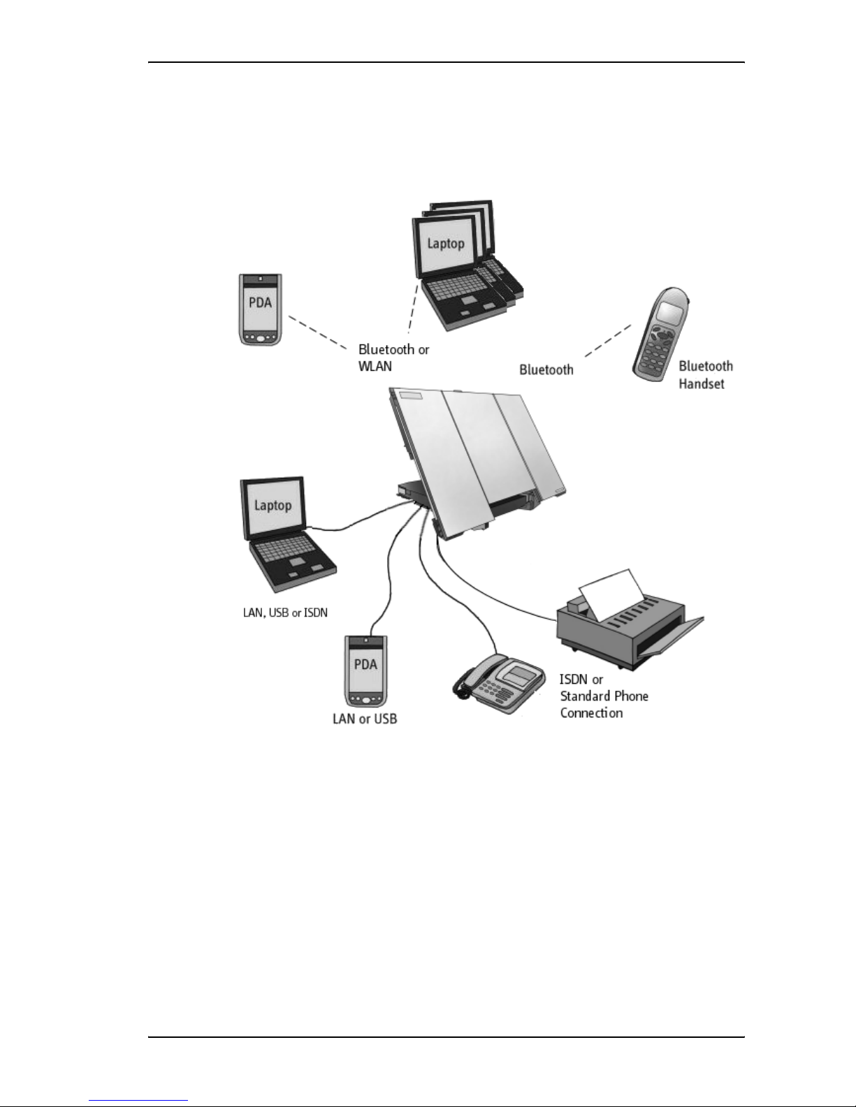
Just plug in a phone, fax, laptop or PDA, or use the Bluetooth® or WLAN interface, point the
antenna towards the BGAN satellite - and you are online.
EXPLORER™ 700 is an essential evolution in satellite communication for governments,
broadcasters and other organizations dependent on relaying information fast under any condition.
TheEXPLORER™ 700 provides access to the highest bandwidth available on the BGAN network –
up to 492 kbps. The system offers multi-user as well as single-user functionality, making it a
flexible solution for a variety of applications.
Page 12

Chapter 1: Introduction
98-122988-B 2
Applications include:
• Internet browsing
•E-mail
• Phone and fax services
• Large file transfers
• Video conferencing and Streaming
• VPN (Virtual Private Network) access to corporate servers
In this chapter
This chapter gives an overview of the BGAN system and services, and introduces the
EXPLORER™ 700.
It also gives an overview of the physical unit and its features and functions.
Page 13
Chapter 1: Introduction
98-122988-B 3
The BGAN system
What is BGAN?
The Broadband Global Area Network (BGAN) is a mobile satellite service that offers high-speed
data up to 492 kbps and voice telephony. BGAN enables users to access e-mail, corporate
networks and the Internet, transfer files and make telephone calls.
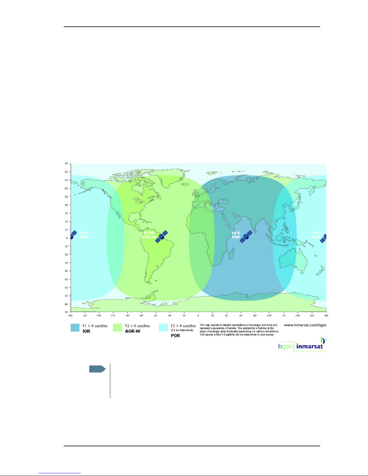
Coverage
The Inmarsat® BGAN services are based on geostationary satellites situated above the equator.
Each satellite covers a certain area (footprint). The coverage map below shows the footprints of the
BGAN system.
Note
The map depicts Inmarsat's expectations of coverage, but does not represent a
guarantee of service. The availability of service at the edge of coverage areas fluctuates
depending on various conditions.
The launch of the F3 satellite (POR) will be determined in due course.
Page 14
Chapter 1: Introduction
98-122988-B 4
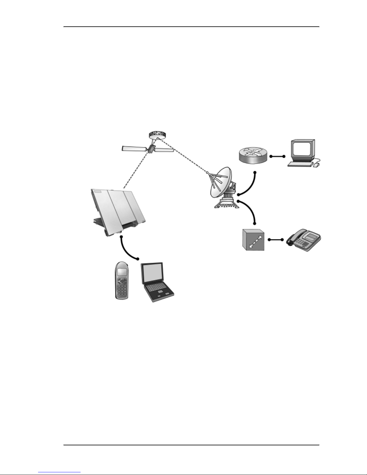
Overview of the BGAN system
A complete BGAN system includes the EXPLORER™ 700 with connected peripherals, the BGAN
satellite, and the Satellite Access Station (SAS). The satellites are the connection between your
EXPLORER™ 700 and the SAS, which is the gateway to the worldwide networks (Internet,
telephone network, cellular network, etc.).
Satellite
IP Router
PC
Satellite Access Station
(SAS)
Switch Voice and ISDN
Laptop
Bluetooth
Handset
Circuit Switched Network
Packet Switched Network
EXPLORER™ 700
Page 15

Chapter 1: Introduction
98-122988-B 5
The BGAN services
Supported services
The services currently supported by BGAN comprise:
• A Packet Switched connection to the Internet
• A Circuit Switched (Dialed) connection for voice, fax or data
• Short Messaging Service (SMS)
Packet data service
The BGAN network supports different classes of data connection to the Internet.
• Using a Standard data connection, several users can share the data connection
simultaneously. This type of connection is ideal for e-mail, file transfer, and Internet and
intranet access. The user pays for the amount of data sent and received.
• Using a Streaming data connection, you get an exclusive, high-priority connection, ensuring
seamless transfer of data. This type of connection is ideal for time critical applications like live
video over IP. The user pays for the duration of the connection (per minute charge).
Circuit switched (dialed) service
Two types of circuit switched connection are available:
• Standard Voice. A low-tariff connection for voice only. The voice signal is compressed to
4.0 kbps, which reduces the bandwidth use and consequently the tariff.
• 3.1 kHz Audio. A high quality connection which can be used for Premium Voice, G3 fax,
analog modem or ISDN (speech, G4 fax or 64 kbps UDI/RDI data).
The signal is uncompressed 3.1 kHz audio, which allows for optimum voice quality.
SMS service
The BGAN system provides a Short Messaging Service (SMS) for sending and receiving SMS
messages.
Supplementary services
The BGAN system also provides the following supplementary services:
• Call hold
• Call waiting
•Call forwarding
•Voice mail
• Call barring (using AT commands)
Page 16

Chapter 1: Introduction
98-122988-B 6
Features and interfaces of the EXPLORER™ 700
Features
Simultaneous voice and data communication over BGAN
Full duplex, single or multi-user, up to 492 kbps
Support for streaming IP at 32, 64, 128, 256 kbps
Seamless global coverage
Standard LAN, WLAN, USB, ISDN, Bluetooth and Phone/Fax ports
Integral DHCP/NAT wireless router
Built-in web interface allowing you to manage your phone book, messages and calls, and
customize the terminal to your specific needs
10-32 V DC input
100-240 V AC power adapter
Solar panel direct interface
Detachable lightweight antenna with integral transceiver stand and transceiver-to-antenna
range up to 100 m/328 ft
Compact portable unit, sturdy and reliable construction
Humidity, dust, weather and temperature-resistant design
Rapid deployment and take-down
CE, FCC and GMPCS certified
Page 17
Chapter 1: Introduction
98-122988-B 7
Overview of interfaces
The EXPLORER™ 700 provides a number of interfaces for connection of various types of
computers, fax devices and phones.
Using the interfaces on page 50 describes how to use each of the available interfaces.
Minimizing power consumption
The EXPLORER™ 700 is designed for minimum power consumption. This means that functions that
are not currently used will automatically go into a “sleep mode” to minimize the power
consumption.
In addition to this automatic sleep mode function, you can disable each of the interfaces if they are
not currently used. Note, however, that you will not be able to use these interfaces until you
enable them again. For information on how to enable/disable interfaces, see Enabling or disabling
an interface on page 52.
Page 18
Chapter 1: Introduction
98-122988-B 8
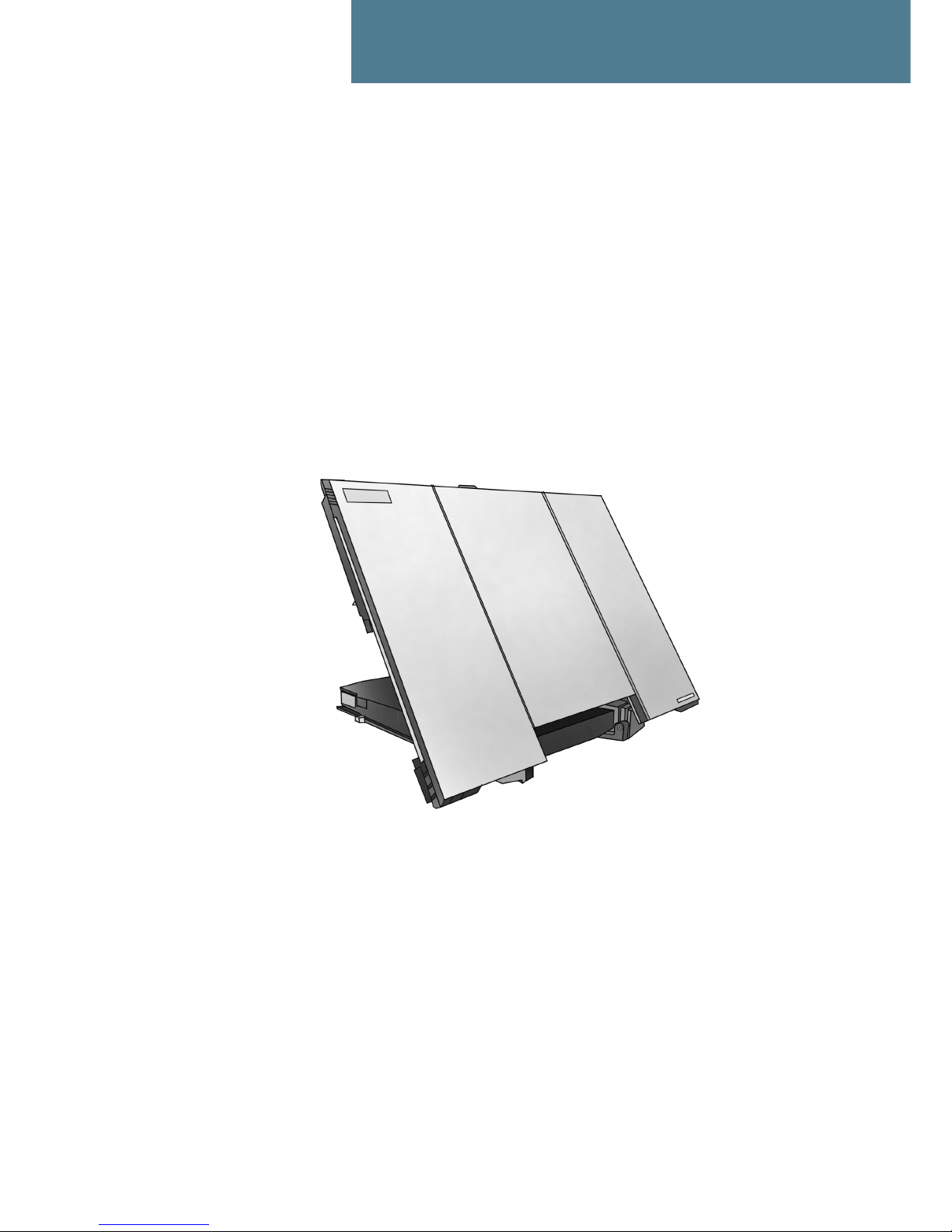
Your EXPLORER™ 700 terminal
Overview
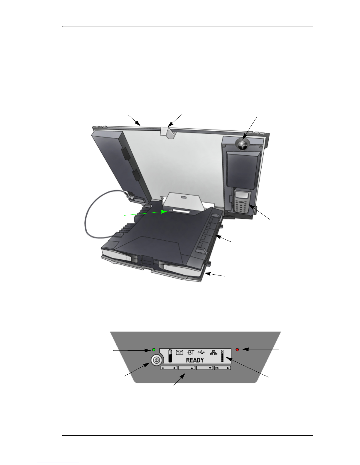
The EXPLORER™ 700 is a compact unit comprising a transceiver with a detachable antenna,
compass, display and keypad, all in one unit.
Display and keypad
The EXPLORER™ 700 has a display and a keypad for displaying status and for setting up the
EXPLORER™ 700.
For information on how to use the keypad and display, and for an overview of the display menu
system, see Using the display and keypad on page 33.
Display and
EXPLORER
™
Bluetooth Handset
Compass
BGAN Antenna
Keypad
Connector Panel
Battery
Transport Lock
Power
Power Button
Keypad
Display
Message
indicator
indicator
Page 19

Chapter 1: Introduction
98-122988-B 9
Light indicators
The EXPLORER™ 700 has two light indicators next to the display: a green power indicator and a
red message indicator.
Green Power indicator
The function of the green Power indicator to the left of the display is as follows:
Red Message indicator
The function of the red Message indicator to the right is as follows:
Behavior of green indicator Meaning
Short flash every 2 seconds The EXPLORER™ 700 is on.
Steady light The battery is charging.
Flashing rapidly A charging error has occurred.
For further information, refer to the Troubleshooting Guide on
page 140.
Off No power or Stealth mode.
Behavior of red indicator Meaning
Flashing An alarm is active or
An SMS message has arrived.
Press OK on the keypad to view the alarm(s) or SMS
message(s).
a
The red light will keep flashing after OK is pressed if
• there are more SMS messages, or
• an alarm is still active.
For information on alarm messages, see Alarm messages
on page 149.
a. If a computer is connected, you can also view alarms and SMS messages in the built-in web interface in the
EXPLORER™ 700. For further information, see Icons in the icon bar on page 86.
Off No messages are present, or the EXPLORER™ 700 is in Stealth
mode.
Page 20

Chapter 1: Introduction
98-122988-B 10
User interfaces
The keypad and display are used for pointing the antenna, for displaying status and for changing
simple parameters.
To obtain full access to all features and for ease-of-use, you should use a computer
(a PC, Laptop or similar) and one of the following:
•The web interface. A built-in web interface for easy configuration and daily use. The web
interface is accessed from a computer connected to the EXPLORER™ 700, using an Internet
browser. No installation of software is needed if you connect using LAN. If you connect using
USB you need to install a USB driver for the computer to recognize the EXPLORER™ 700. See
Using the USB interface on page 72.
For further information on the web interface, see Chapter 5, Using the web interface.
•The BGAN LaunchPad from Inmarsat. BGAN LaunchPad is a computer application used to
control terminals in the BGAN system. LaunchPad is provided on the Inmarsat BGAN CD-ROM
supplied with your EXPLORER™ 700. For information on how to use the LaunchPad, refer to
the manual on the Inmarsat CD-ROM.
Additionally, it is possible to control the EXPLORER™ 700 using AT Commands. Refer to
Appendix B, AT commands.
Antenna
The white part of the EXPLORER™ 700, including the support bracket, is the detachable antenna
module. The antenna module comprises a GPS (Global Positioning System) antenna and a BGAN
antenna. Bluetooth and Wireless LAN antennas are integrated in the transceiver unit.
Compass
The EXPLORER™ 700 also provides a compass to help positioning the
antenna. For further information on how to use the compass, see
Pointing the antenna on page 25.
Battery
The EXPLORER™ 700 comes with a rechargeable battery, which is easily inserted. The battery is
automatically recharged when power is applied to the EXPLORER™ 700. Steady green light
indicates that the battery is charging.
SIM card
The EXPLORER™ 700 has two SIM slots, USIM #1 and USIM #2, located behind the battery. Only
USIM #1 is currently in use. USIM #2 is reserved for future use.
The SIM (Subscriber Identity Module) card used for the EXPLORER™ 700 is a standard SIM card,
which is acquired from the Airtime Provider.
The EXPLORER™ 700 requires a SIM card to go online and to access the settings of the
EXPLORER™ 700. Without a SIM card you can only see the Main screen of the display system
Page 21

Chapter 1: Introduction
98-122988-B 11
showing battery status etc. Using the web interface, you can view the properties of the
EXPLORER™ 700 and upload software without inserting a SIM card. Upload of software, however,
requires an Administrator user name and password.
Matrix of services and communication interfaces
The following table shows which services can be accessed from which interfaces, and which types
of equipment can be used.
What’s next?
This chapter has provided an overview of the BGAN system and of the EXPLORER™ 700.
The next chapters will go into more detail about how to set up and use the EXPLORER™ 700. The
following chapter, Getting started, explains how to unpack and start up the EXPLORER™ 700, and
how to point the antenna in order to get the best possible signal.
Service
Interface on the EXPLORER™ 700
Phone/
Fax
Bluetooth USB LAN WLAN ISDN
Display/
Keypad
Circuit Switched Connection
3.1 kHz
Audio
Analog
telephone
Bluetooth
handset
ISDN
telephone
G3 Fax
machine
G4 fax
machine
Standard
Voice
Analog
telephone
Bluetooth
handset
ISDN
telephone
Data
Computer
with
analog
modem
Computer Computer
(56 kbps/
64 kbps)
Computer
with ISDN
modem
Packet Switched Connection
Data
multi-user
Computer Computer Computer
Data
single-
user
Computer Computer Computer Computer
SMS
Computer Computer Computer Computer Computer
with ISDN
modem
View only
Page 22
98-122988-B 12
Chapter 2
Getting started 2
In this chapter
This chapter describes:
• what is included in the delivery,
• how to insert and remove the battery and SIM card, and
• how to start up the EXPLORER™ 700 and make the first call or data session.
Unpacking and assembling
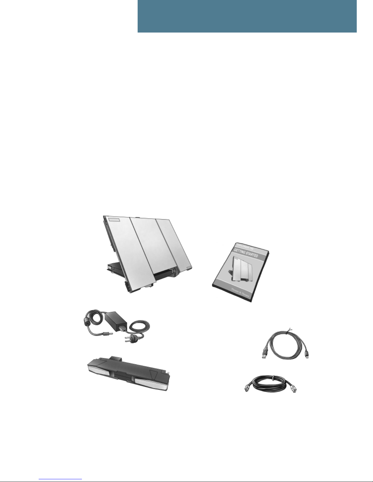
Unpacking
Unpack the EXPLORER™ 700 and accessories and check that the following items are present:
41.5 cm antenna cable
LAN cable
AC/DC adapter/charger
Battery
USB cable
EXPLORER™ 700
Getting Started Kit
- Getting Started leaflet
- Quick Guide
- EXPLORER™ 700 CD-ROM
- BGAN LaunchPad CD-ROM
containing:
10 m antenna cable
Page 23
Chapter 2: Getting started
98-122988-B 13
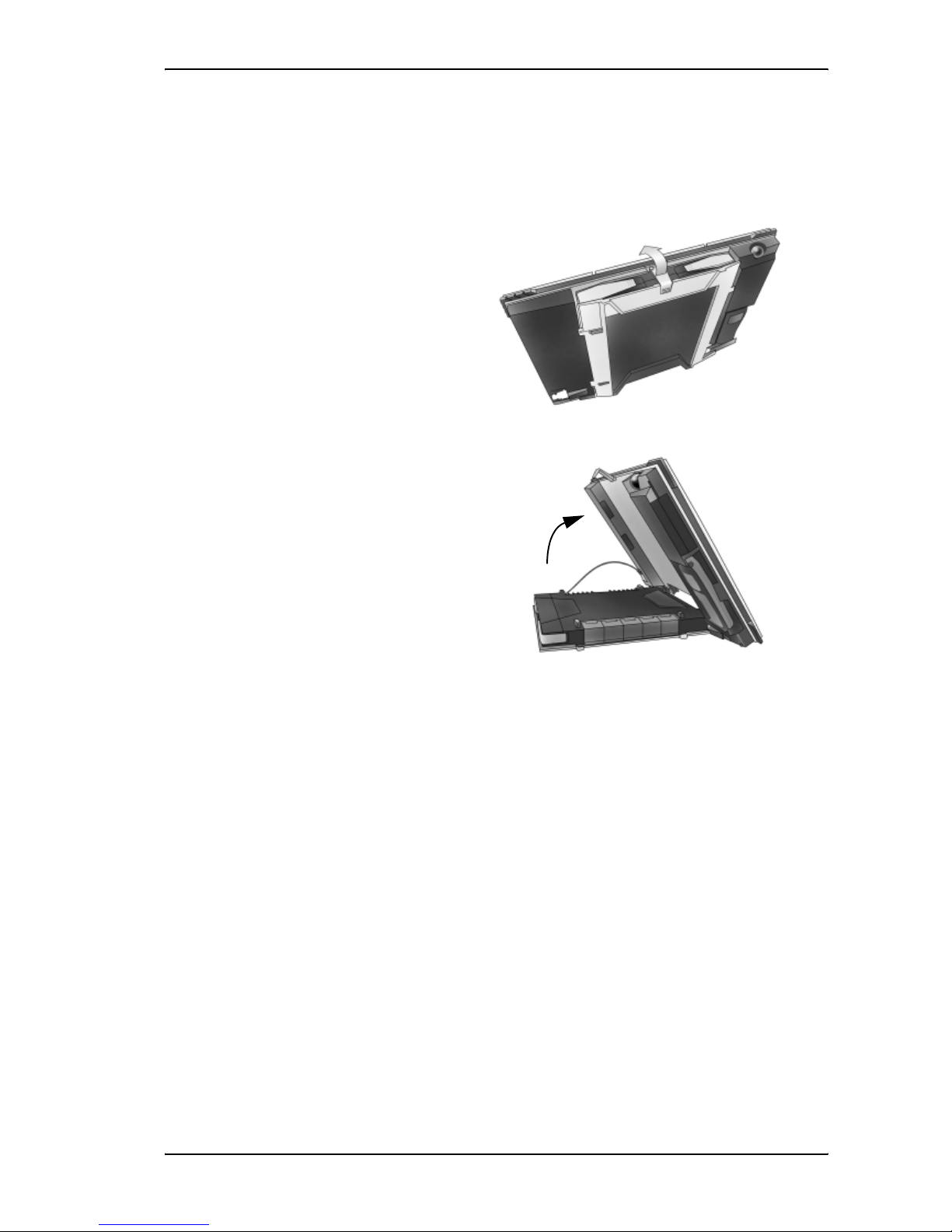
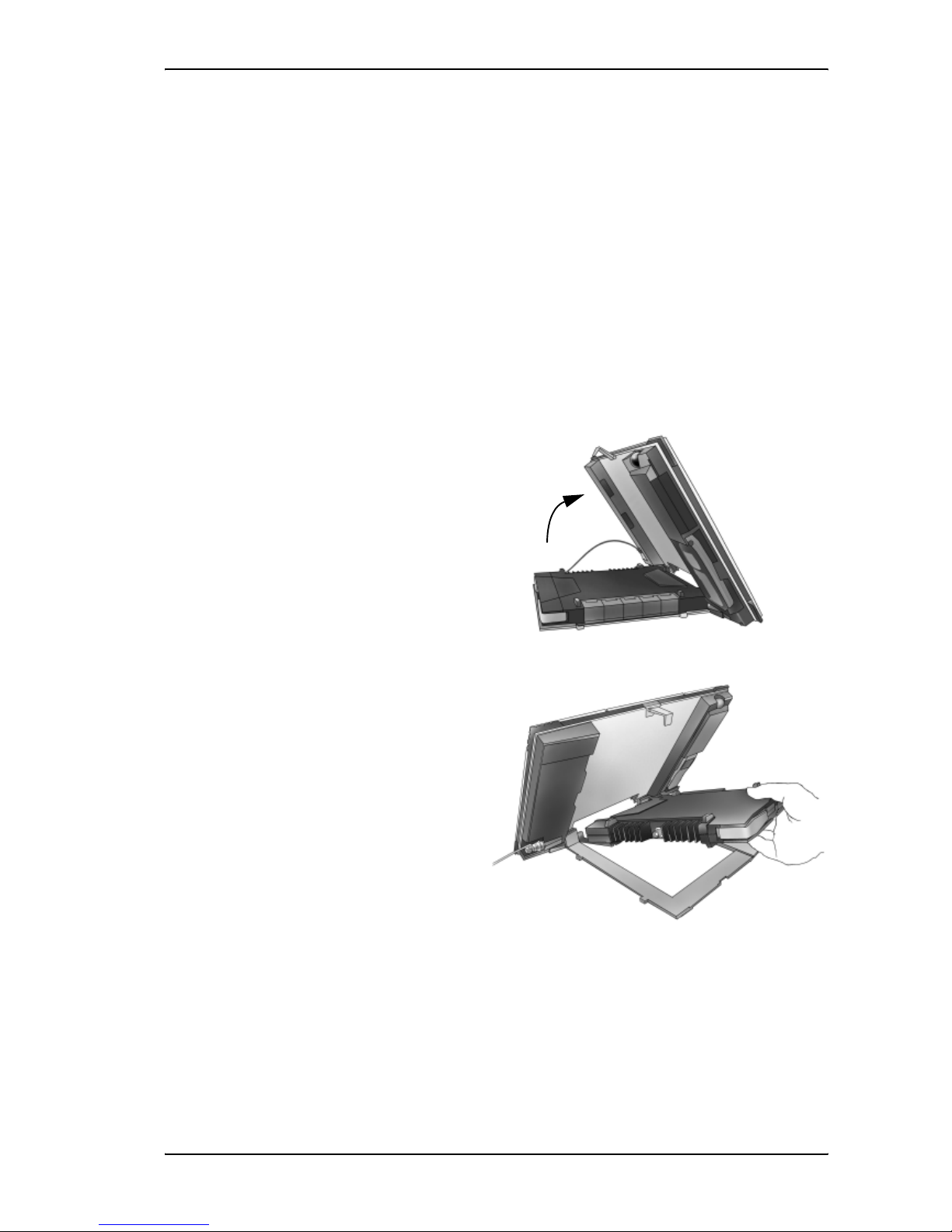
Opening the transport latch
The EXPLORER™ 700 has a transport latch, securing the transceiver and antenna during transport.
1. Open the latch as shown.
2. You can now flip up the antenna
module and access the keypad and
connectors on the EXPLORER™ 700.
Page 24
Chapter 2: Getting started
98-122988-B 14
Detaching the antenna
You have two options for using the EXPLORER™ 700 antenna:
• Attached. You can go through the pointing process with the antenna and transceiver attached
as one unit. This means you have to move the entire terminal in order to point the antenna
towards the BGAN satellite. If you choose this option, make sure you connect all cables
including the short antenna cable, and enter the PIN code, before pointing the antenna. If
not, you may accidently move the antenna when you connect cables or enter the PIN code.
• Detached. You can detach the antenna and use it as a separate antenna. With the antenna
separated from the transceiver, it is easier to use the transceiver without accidently moving
the antenna. Also, you can choose the optimum location for the antenna while keeping the
transceiver in a more comfortable location.
To detach the antenna, do as follows:
1. Flip up the antenna module.
2. Gently lift the transceiver out of the
antenna frame.
After detaching the antenna connect an antenna cable between the antenna and the
EXPLORER™ 700 as described in Connecting the antenna on page 79.
Page 25
Chapter 2: Getting started
98-122988-B 15
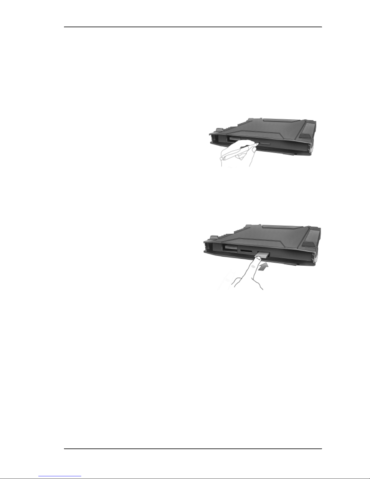
Inserting the SIM card
The EXPLORER™ 700 is delivered with the battery separated from the terminal. If the battery is
already inserted, remove it as described in Removing the battery on page 17.
There are two SIM slots in the EXPLORER™ 700, marked USIM #1 and USIM #2. USIM #2 is
reserved for future use.
The SIM card is provided by your Airtime Provider. Insert the SIM card as follows:
1. First press the eject button at the SIM slot
marked USIM #1 to release the SIM card
holder.
Use a pen or similar to press the button.
The SIM card holder is a small plastic frame
designed to hold the SIM card.
2. Take the SIM card holder out and place the
SIM card in the holder, with the printed
side visible.
3. Insert the holder with the SIM card into
the SIM slot marked USIM #1.
Place the holder with the printed side
facing down.
4. Press gently until it clicks.
Page 26
Chapter 2: Getting started
98-122988-B 16
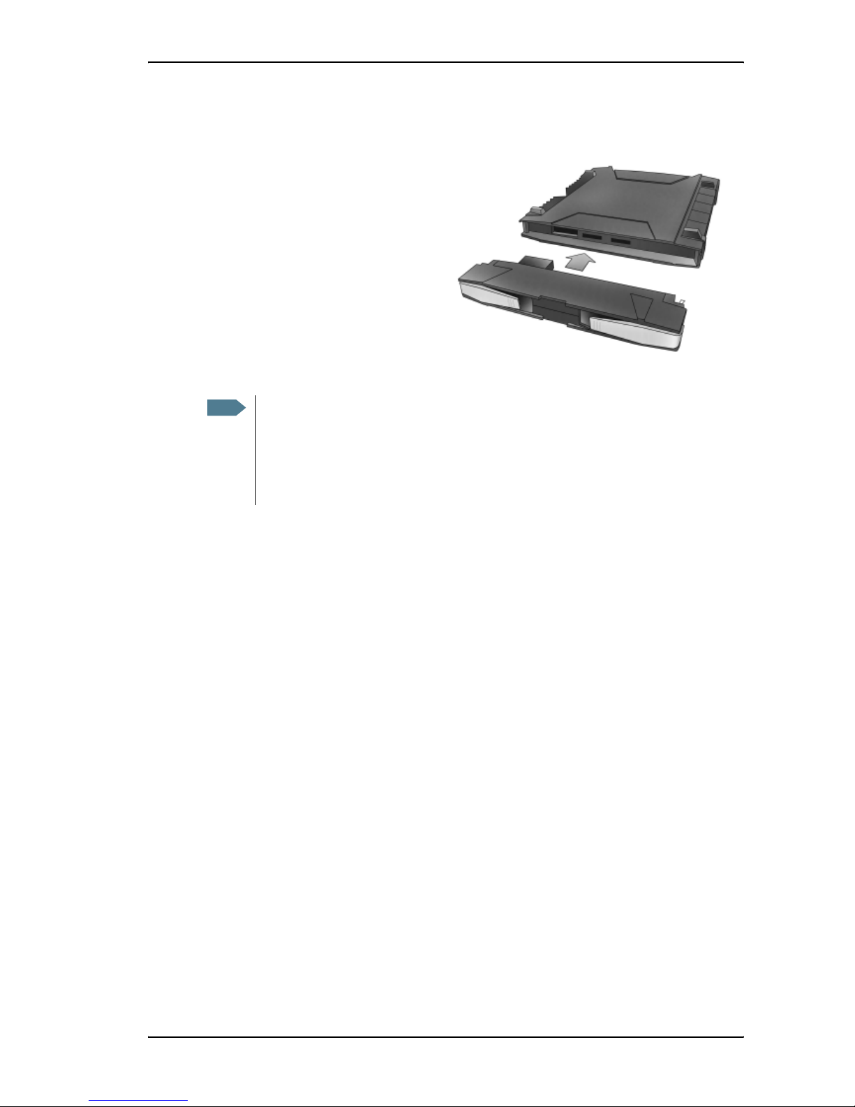
Inserting the battery
Do as follows:
1. Insert the battery.
Make sure the battery is positioned
correctly as shown.
2. Press gently until it locks.
Note
Before using the terminal the first time: To ensure accurate information on the battery
capacity you should fully charge, then fully discharge the battery (until the
EXPLORER™ 700 closes down automatically), and finally recharge the battery. The
EXPLORER™ 700 can be used during the discharging process, but the remaining battery
capacity may not be displayed correctly.
For information on how to recharge the battery, see Recharging the battery on page 137.
Page 27
Chapter 2: Getting started
98-122988-B 17
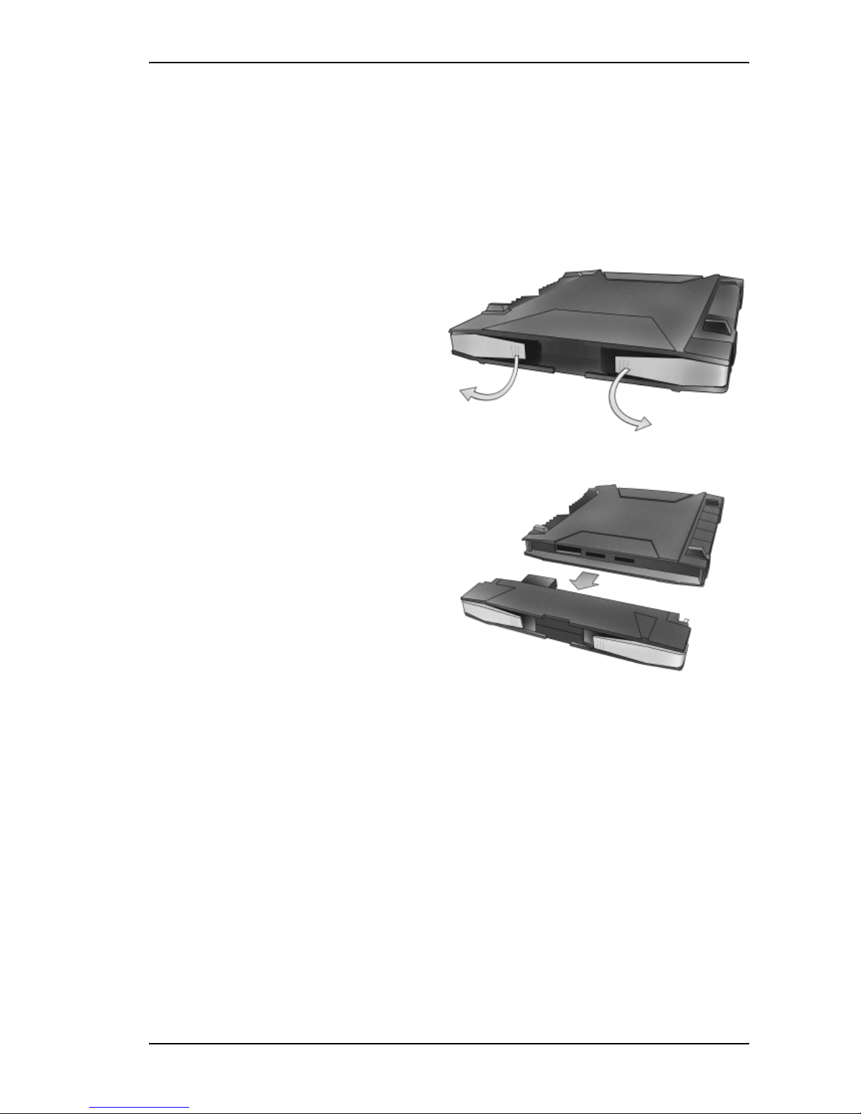
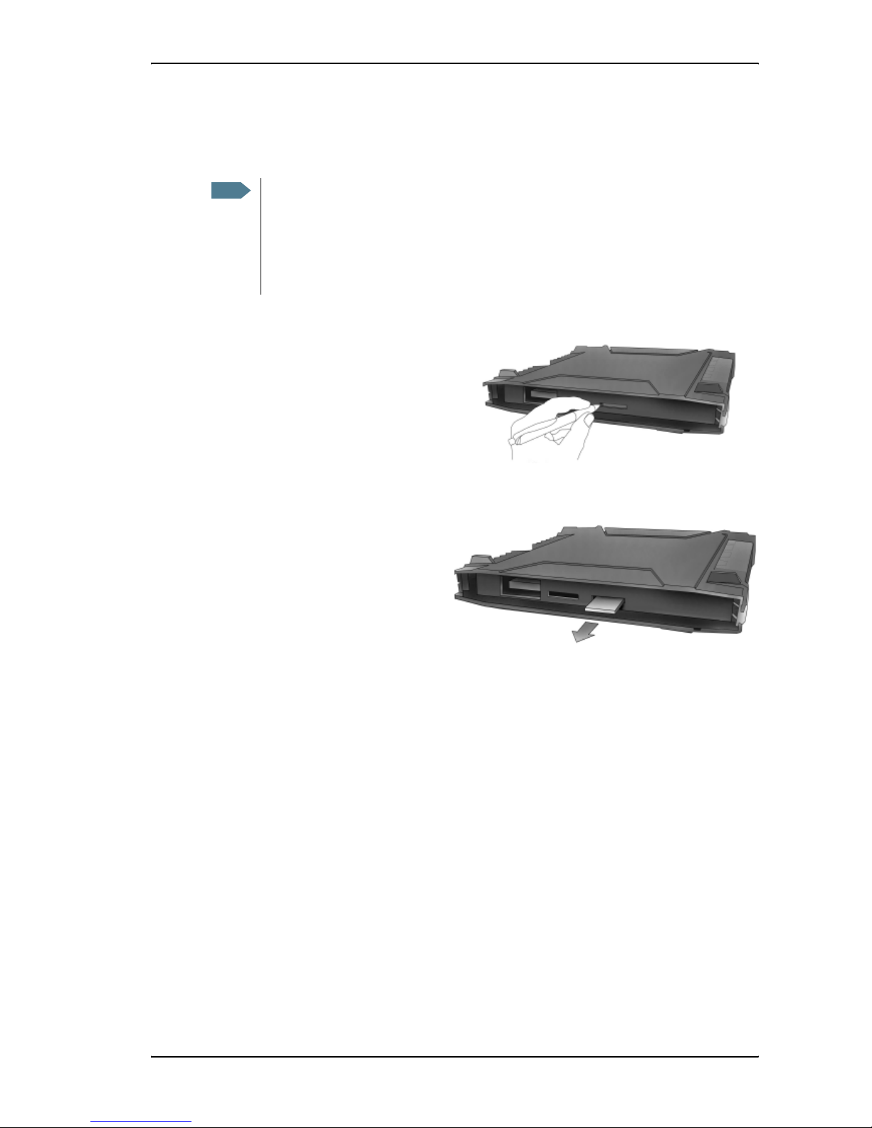
Removing the battery
To remove the battery, do as follows:
1. If the transceiver and antenna are attached, open the transport latch and flip up the antenna
module. Then gently lift the transceiver out of the antenna frame.
2. Open the battery latches as shown.
3. Remove the battery.
Page 28
Chapter 2: Getting started
98-122988-B 18
Removing the SIM card
To remove the SIM card, first remove the battery as described in Removing the battery on page 17.
Remove the SIM card as follows:
1. Press the eject button next to the SIM
slot marked USIM #1.
Use a pen or similar to press the
button.
2. Remove the SIM card holder.
3. Take the SIM card out of the holder and reinsert the holder.
Note
When the SIM card is removed, you cannot use the display menu system nor make calls
or start data sessions.
Only emergency calls are allowed, and only if permitted by the network.
However, if you have an administrator user name and password, you can upload
software using the web interface. For further information, see Uploading software on
page 125.
Page 29
Chapter 2: Getting started
98-122988-B 19
Connecting cables
After inserting SIM card and battery, connect all relevant cables.
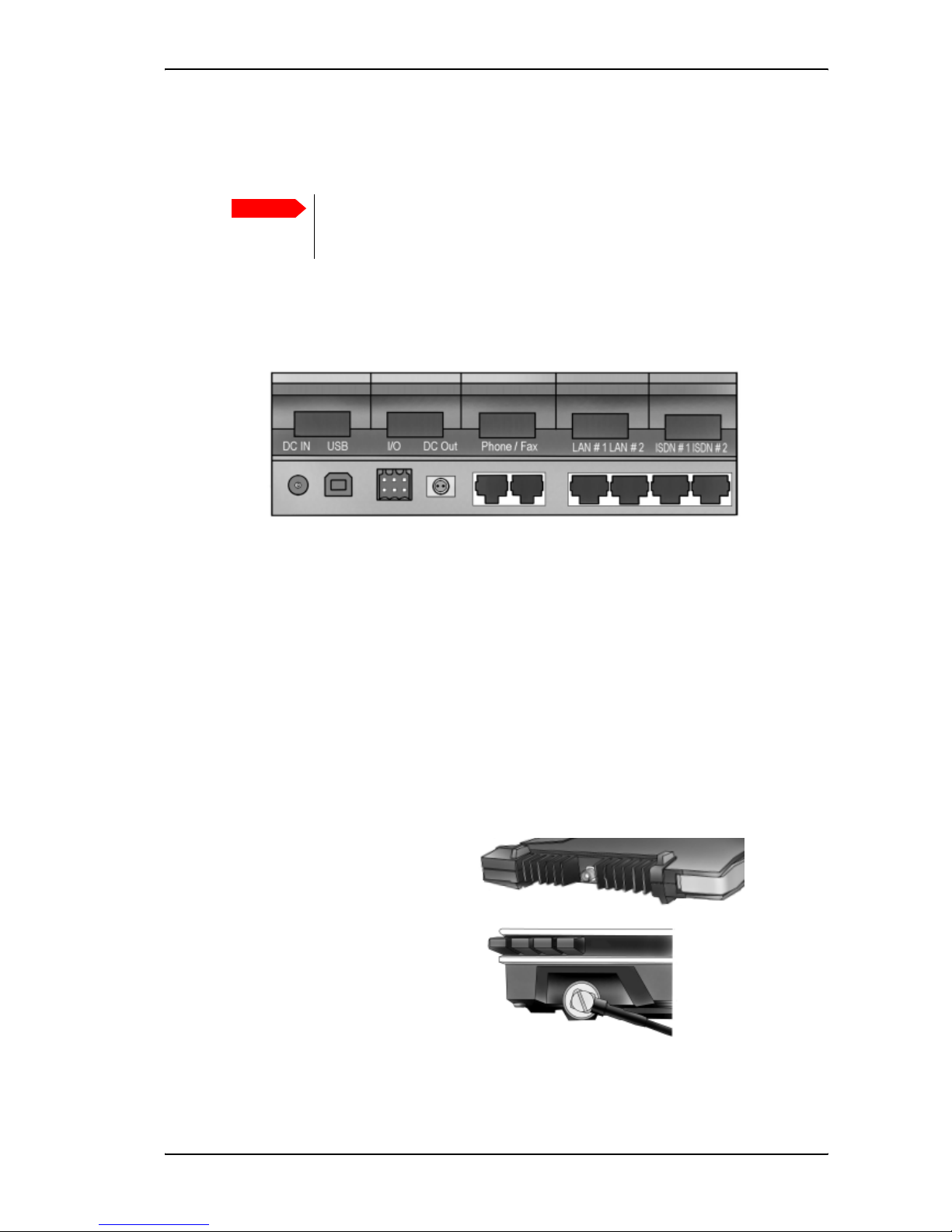
Connector panel
The connector panel is placed on the side of the EXPLORER™ 700 and has the following
connectors:
• 1 DC power input connector for connection to10-32 V DC.
• 1 USB connector
• 1 Input/Output connector for external control or signaling
• 1 Bluetooth Handset charging connector (marked DC OUT)
• 2 Phone/Fax connectors
• 2 LAN connectors
• 2 ISDN connectors
Antenna connectors
In addition to the connectors in the connector panel, the EXPLORER™ 700 has two connectors for
connecting the antenna,
• one on the transceiver
and
• one on the antenna
For information on how to connect to a specific interface, see the corresponding section in
Chapter 4, Using the interfaces. The end of this section describes how to connect to power.
Important
If you are using the transceiver with the antenna attached, connect the cables
before making the final adjustment of the antenna position. Otherwise you may
accidently move the antenna when you connect the cables.
Page 30
Chapter 2: Getting started
98-122988-B 20
Before connecting to power
You can connect to external power or use the battery delivered with your EXPLORER™ 700.
Refer to Power input on page 158 for specifications and pin-out for the DC Power input.
If you are connecting to a 100-240 V AC electrical outlet, use the AC/DC adapter included with your
EXPLORER™ 700.
Alternatively, you may connect to 12/24 V DC in a car., or to a solar panel. Note that the battery
must be inserted before you connect the EXPLORER™ 700 to a solar panel.
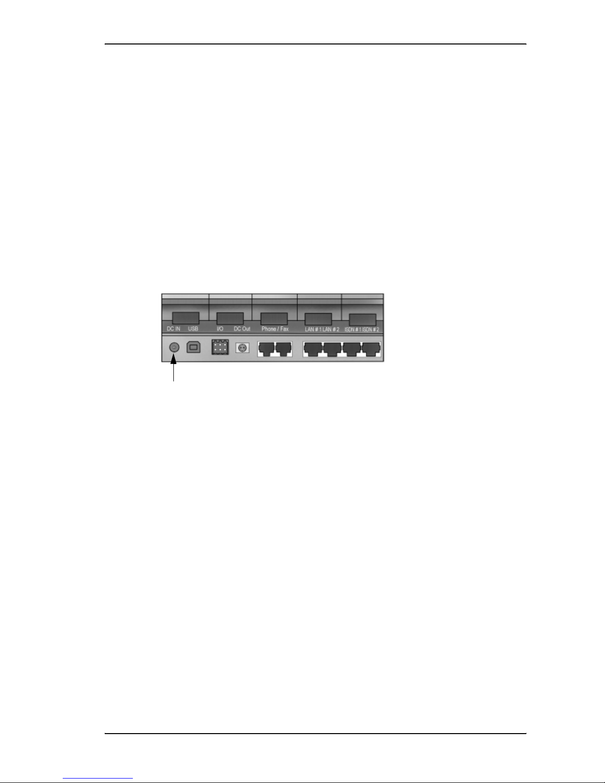
Connecting to power
You can connect the DC input to power without the battery inserted. Note, however, that if you are
connecting a solar panel, the battery must be inserted.
If the battery is inserted when you apply power to the EXPLORER™ 700, the battery is
automatically recharged.
Connecting to a 100-240 V AC electrical outlet: Connect the AC/DC adapter to the DC Power input
on the side of the EXPLORER™ 700. Then connect the power cable between the 100-240 V AC
electrical outlet and the AC/DC adapter.
Connecting to 12/24 V DC in a car: Connect the charger cable between the DC Power input of the
EXPLORER™ 700 and the cigarette lighter socket in the car. A suitable charger cable is available
from Thrane & Thrane.
Connecting to a solar panel: The battery must be inserted in the EXPLORER™ 700. Connect your
cable between the solar panel and the DC power input of the EXPLORER™ 700. The battery is
automatically charged. For further information, see Using a solar panel on page 80.
Page 31

Chapter 2: Getting started
98-122988-B 21
Powering the EXPLORER™ 700
Automatic power up
The default behavior of the EXPLORER™ 700 is to power up automatically when you connect the
power cable. If you wish, you can change this power up mode, so that the EXPLORER™ 700 is only
powered if the Power button is pressed.
For further information on power up mode, see Setting the power up mode on page 44 or Power up
behavior on page 102.
Switching the EXPLORER™ 700 on/off
To switch on the EXPLORER™ 700,push the
Power button next to the display and hold it
down until the green Power indicator lights up.
It normally takes one or two seconds.
To switch off the EXPLORER™ 700, push the Power button again and hold it until the display
shows SWITCHING OFF....
After switching on the EXPLORER™ 700 you will
be prompted for a PIN (Personal Identification
Number), unless the PIN is disabled (e.g. using
the BGAN LaunchPad).
For information on the options after power on, see
the next section.
WARNING! When the EXPLORER™ 700 is powered on, stay clear of the antenna
front! The antenna emits radio frequency energy, not only when the display shows
DATA ACTIVE. Always keep a minimum distance of 1 m from the antenna front.
Power
button
Power
indicator
Page 32

Chapter 2: Getting started
98-122988-B 22
Options for the start-up procedure
Overview of the start-up options
You have different options for the start-up procedure. Each of these options are briefly described
in this section.
For information on how to enter PIN and point the antenna, see the subsequent sections.
The following drawing shows the options available after power on.
The numbers on the drawing refer to the different start-up options described in the following
sections.
Note
If the use of PIN is disabled, e.g. from the BGAN LaunchPad, the display sequence is the
same as after successfully entering the PIN. This means that after power on, you will see
the Signal strength screen.
Power on
ENTER PIN?
Cancel OK
ENTER PIN
*-
"Signal Strength"
Cancel OK
"Signal Strength"
Cancel OK
"Main screen" "Main screen"
You can access the
menu system but you
cannot use the BGAN
network.
You can access the
menu system and use
the BGAN network.
"Main screen"
You cannot access the
menu system, and you
cannot use the BGAN
network.
"Main screen"
You cannot access the
menu system, and you
cannot use the BGAN
network, except for
emergency calls, if
allowed by the network.
Menu system Menu system
12
3
Page 33

Chapter 2: Getting started
98-122988-B 23
“Full” procedure (1)
After power on, enter the PIN and then point the antenna.
In this mode you have full access to the EXPLORER™ 700, that is you can use the menu system and
communicate on the BGAN network.
The display will show READY when the menu system is not activated.
“Off-line” procedure (2)
After power on, enter the PIN, but cancel pointing.
In this mode you can use the menu system, but are not able to communicate on the BGAN
network.
The display will show POINT NOW? when in the Main screen.
Press S or T to enter the menu system.
When you want to point the antenna, press OK from the Main screen.
“Emergency” procedure (3)
After power on, cancel the PIN and then point the antenna.
In this mode you can only place emergency calls, and only if permitted by the network. You are not
able to access the menu system nor to communicate on the BGAN network (apart from emergency
calls), until you enter the PIN.
The display will show ENTER PIN?
If you press OK you can enter the PIN. No other options are available from the keypad.
From the web interface you can view properties and, if you have an administrator password,
upload software.
Page 34

Chapter 2: Getting started
98-122988-B 24
Entering the SIM PIN
Overview
You have to enter a PIN to use the EXPLORER™ 700, unless the use of PINs is disabled e.g. from
the BGAN LaunchPad.
The first time you are asked for a PIN, you can choose to cancel (press C). If you cancel, you are
asked again after pointing is completed. At that point you must enter the PIN to be able to
continue.
Entering the PIN
To enter the PIN using the display and keypad, do as follows:
1. When you are asked for a PIN, press OK.
2. Press S or T a number of times until the
first digit is correct.
3. Press OK to go to the next digit.
When OK is pressed, the previous digit is
indicated by a *.
To correct an entered digit, press C to go back and use the S and T buttons again.
4. After entering the last digit with OK, press OK again to apply the PIN.
For further information, see Using the display and keypad on page 33.
You can enter the PIN using a phone or computer connected to the EXPLORER™ 700. For further
information, see Entering the SIM PIN using a phone on page 59 or Entering the SIM PIN in the
web interface on page 88.
Wrong PIN
You have 3 attempts to enter the PIN, before you are asked to enter the PUK (Pin Unblocking Key).
The PUK is supplied with your SIM card.
Enter the PUK followed by a new PIN of your own choice. The PIN must be from 4 to 8 digits long.
Note
At this point the EXPLORER™ 700 may make a sound. This sound is used for pointing the
antenna. To toggle the pointing sound on/off, press S or T.
Important
If you enter a wrong PUK 10 times, the SIM card will no longer be functional, and
you have to contact your Airtime Provider for a new SIM card.
Page 35

Chapter 2: Getting started
98-122988-B 25
Pointing the antenna
The importance of pointing
In order to obtain the best possible signal at the
lowest possible cost, it is important that the
EXPLORER™ 700 antenna is pointed correctly
towards the satellite.
The antenna must have a clear line of sight to the
satellite without any obstacles blocking the signal,
and the pointing direction of the antenna should be
as accurate as possible.
The next sections describe how to point the antenna for the best possible signal.
Pointing data
If the position of the satellite in relation to the EXPLORER™ 700 is known, you can use the
compass to roughly point the antenna in the right direction. If you know the Azimuth and the
Elevation, you can use this data to adjust the antenna.
•The Azimuth is the horizontal rotation angle relative to
North (moving clockwise).
•The Elevation is the vertical rotation angle relative to
horizontal. This means that an Elevation of 0°
corresponds to the EXPLORER™ 700 being in an upright
position, pointing towards the horizon.
The compass has 7 lines dividing the Elevation scale into 6
spaces. The space between two lines corresponds to 15°.
The Elevation is measured where the lines meet. This compass
shows an Elevation of
30° (2 spaces up from the first line) and
an Azimuth of 270° (antenna pointing towards West).
Important
Incorrect pointing may result in poor quality of the signal, and in some cases
retransmission may be necessary. This could mean you will be paying more than
necessary for your transmission.
Note
The above explanation assumes that the compass shows the exact orientation. Please
take into consideration the possible deviation and variation that can occur, e.g. because
of the geographical location or the presence of magnetic objects.
N = 0°
S = 180°
E = 90°W = 270°
Front of antenna
Page 36

Chapter 2: Getting started
98-122988-B 26
Required signal strength
As a rule of thumb, the signal strength should typically be 45 dBHz or more for the
EXPLORER™ 700 to be able to establish a call or data session. However, the required signal
strength can vary depending on a number of factors, such as weather conditions and location.
Do not block the antenna signal with your hands
Obtaining a GPS fix
The EXPLORER™ 700 must acquire its own location from the GPS satellites before it can register
on the BGAN network. This is called obtaining a GPS fix.
If the antenna is placed in an open location with a wide view to the sky, the EXPLORER™ 700 will
probably obtain the GPS fix automatically while you are pointing towards the BGAN satellite.
However, if part of the view to the sky is blocked, and/or the Elevation is very low, it may
sometimes be difficult for the GPS antenna to “see” a sufficient number of GPS satellites. In such
circumstances, try the following:
1. Place the antenna flat on an even surface, pointing straight upwards with a clear view to as
much of the sky as possible.
2. When the GPS fix is obtained, you can start pointing towards the BGAN satellite.
To see the GPS status, enter the display menu system by pressing S or T and select
PROPERTIES > GPS STATUS. For further information, see Viewing the GPS status on
page 45.
Important
When pointing the antenna, do not touch the front of the antenna module. For your
safety, always maintain a distance of minimum 1 m from the front face of the
antenna. Also, if you place your fingers on the antenna you will be blocking the
signal, and the antenna will not work efficiently.
Hold the support bracket and the transport lock of the antenna while pointing.
Page 37

Chapter 2: Getting started
98-122988-B 27
Pointing the antenna towards the satellite
You can use the EXPLORER™ 700 with the antenna attached to the transceiver, or you can detach
the antenna from the transceiver and use it as a separate antenna unit. For further information,
see Using the EXPLORER™ 700 antenna on page 79.
To help you obtain the best possible signal strength, the EXPLORER™ 700 uses a pointing sound
from both antenna and transceiver to indicate the signal strength during pointing. The frequency
of the tone increases with the signal strength.
You can toggle the pointing sound on/off by pressing S or Ton the keypad.
Do as follows to point the antenna:
1. While observing the built-in compass of the
EXPLORER™ 700, rotate the antenna left or
right until it points in the correct horizontal
direction, known as the Azimuth. Refer to
Pointing data on page 25.
Hold the transport lock and the support
bracket while moving the antenna. Do not
place your hands on the antenna.
2. Tilt the antenna slowly up or down until it
points in the correct vertical direction, known
as the Elevation.
Hold the transport lock and the support
bracket while moving the antenna. Do not
place your hands on the antenna.
3. After passing the PIN screen, the display shows
the current satellite signal strength. Use this
information to fine-adjust the antenna position
as shown in step 1 and 2.
Remember not to touch the antenna part!
If the right most part of the signal strength bar is grey, it indicates that the level has previously
been higher than the current level.
Important
When fine-adjusting the antenna, the display may take a while to update the
signal strength. Wait a second or two after each move to make sure the display
is updated.
Page 38

Chapter 2: Getting started
98-122988-B 28
4. When you have the highest signal strength you
can obtain, press OK on the keypad.
The EXPLORER™ 700 now tries to establish a connection to the BGAN network.
The display shows the progress as follows:
• SEARCHING:
The EXPLORER™ 700 searches for the network operator. Note that the search procedure
can be very short, so you may not see this text.
• REGISTERING:
The EXPLORER™ 700 is registering itself on the network.
If the GPS position has not yet been acquired at this point, the display will show
NO GPS. For further information, see the Troubleshooting Guide on page 141.
• READY or DATA ACTIVE:
READY means the EXPLORER™ 700 is registered on the network and is ready to go online.
If you have already connected a computer, the display shows DATA ACTIVE instead of
READY.
CANCEL: If you press C instead of OK, you exit the pointing menu and the display shows the Main
screen with the message POINT NOW?.
If the PIN has been accepted, you now have access to the menu system, but you will not be able to
connect to the BGAN network, because the signal strength has not yet been accepted.
Note
The display may show a different text than READY or DATA ACTIVE if there is more
important information to show. For example, the display will show ENTER PIN? if you
pressed C at the first request for a PIN. See also the Troubleshooting Guide on page 141.
Page 39

Chapter 2: Getting started
98-122988-B 29
Making the first call
Introduction
After connecting cables, entering the PIN and pointing the antenna, you are ready to make or
receive the first call.
The following sections provide a short guide to making calls. For more detailed information, see
Making or receiving a phone call with the EXPLORER™ 700 on page 60.
Making a call from the EXPLORER™ 700
Your phone must be connected to the relevant interface. For further information, see
•Standard phone: Before connecting to the Phone/Fax interface on page 56
•ISDN phone: Before connecting to the ISDN interface on page 57.
• Bluetooth handset: Pairing devices in which you can enter a passkey on page 53.
To make a call from a phone connected to the EXPLORER™ 700, dial
00 <country code> <phone number> followed by # or off-hook key (# on analog phones and ISDN
phones, off-hook key on Bluetooth handsets).
Example: To call Thrane & Thrane in Denmark (+45 39558800) from an analog phone,
dial 00 45 39558800 #
Making a call to the EXPLORER™ 700
To make a call to a phone connected to the EXPLORER™ 700, dial
+870 <Mobile subscriber number>
• + is the prefix used in front of the country code for international calls. This is 00 when calling
from most countries in Europe and from many other countries.
• Mobile subscriber number: The mobile subscriber number of the EXPLORER™ 700 you are
calling.
If the mobile subscriber numbers of the EXPLORER™ 700 are available on the SIM card, they
are listed in the display menu system of the EXPLORER™ 700 under PROPERTIES >
MOBILE NUMBERS. If they are not available, refer to your airtime subscription.
Example: If you are calling from Denmark and the mobile subscriber number for 3.1 kHz Audio is
772112345 on your EXPLORER™ 700, and you want to make a call to the EXPLORER™ 700
using 3.1 kHz Audio, dial 00 870 772112345.
Note
There are two voice numbers, one for 3.1 kHz Audio and one for Standard Voice.
Page 40

Chapter 2: Getting started
98-122988-B 30
Making a call from one EXPLORER™ 700 to another EXPLORER™ 700
To make a call from one EXPLORER™ 700 to another EXPLORER™ 700,
dial 00 870 <Mobile subscriber number>.
Receiving a call
To be able to receive a call, the phone must be connected to the correct interface of the
EXPLORER™ 700 (Phone/Fax, ISDN or Bluetooth).
To be able to receive a call with a Bluetooth handset, the handset must be paired with the
EXPLORER™ 700. For information on how to pair Bluetooth devices, see Bluetooth pairing on
page 53.
You can see unanswered calls in the CALLS menu of the display and the web interface.
Note
A connected phone will only ring if the call type is set correctly. For information on call
types, see Selecting the call type on page 54.
Page 41

Chapter 2: Getting started
98-122988-B 31
Making the first data connection (LAN)
Before connecting to the LAN interface
For the LAN (Local Area Network) interface to work without any further setup, the computer must
be set up to obtain an IP address and a DNS server address automatically.
To check these settings on your computer, do as follows (For Windows® XP):
1. From the Start menu, select Connect To > Show All Connections.
2. Double-click Local Area Connection and click Properties.
3. Select Internet Protocol (TCP/IP) from the list and click Properties.
Make sure both fields are set to obtain an address automatically.
Page 42

Chapter 2: Getting started
98-122988-B 32
Connecting to the LAN interface
Do as follows:
1. Connect the LAN cable to the network interface of your computer.
A suitable cable is provided with your EXPLORER™ 700.
2. Connect the other end of the
cable to one of the LAN
connectors on the
EXPLORER™ 700.
3. Start up and point the EXPLORER™ 700 as described earlier in this chapter.
4. Power on the computer.
5. When power up and pointing is completed, check the connection e.g. by starting your Internet
Browser.
You may have to disable the Proxy server settings in your browser. For further information,
see Browser settings on page 84.
What’s next?
After reading this chapter you should be able to start up the EXPLORER™ 700 and make a simple
data or voice connection.
The next chapters provide more information on the user interfaces and the setup of the
EXPLORER™ 700. The following chapter, Using the display and keypad, explains the display menu
system, which is the basic tool for setting up the EXPLORER™ 700.
Page 43

98-122988-B 33
Chapter 3
Using the display and keypad 3
In this chapter
This chapter describes how to use the built-in display menu system of the EXPLORER™ 700.
It contains an overview of the entire menu system followed by a description of each menu.
It also explains the symbols and messages that may appear in the display, and describes how to
navigate using the keypad.
Menu overview
Main menu
The items of the main menu are:
• MESSAGES
shows all incoming SMS messages and allows you to open or delete each message or delete
all messages.
• CONNECT
shows a list of the Streaming Profiles that are defined and selected for the LAN interface using
the web interface. The CONNECT menu allows you to start and stop data sessions with the
listed Streaming Profiles.
• CALLS
shows missed, received and outgoing calls and data sessions.
• SETTINGS allows you to
• restart the pointing procedure,
• set display backlight and contrast,
• set audio indications on or off,
• enable or disable each interface,
• enable or disable stealth mode (a terminal mode where lights and sound are off),
• set the power up mode, and
•restore settings.
• PROPERTIES shows:
• known and accepted Bluetooth devices,
•GPS status,
• Terminal information (IP address, hardware and software numbers, IMEI number),
• Mobile numbers
• Voice mail number, and
• a list of active alarms.
Page 44

Chapter 3: Using the display and keypad
98-122988-B 34
• HELP DESK
shows the phone number to the Airtime Provider, if available.
For information on how to navigate in the menu system, see Navigating the display and keypad on
page 37.
Menu drawing
The below drawing shows an overview of the menus in the display menu system of the
EXPLORER™ 700.
The next section shows an overview of the start-up sequence before entering the menu system.
The menus are further described in the following sections of this chapter.
2 SECONDS
5 SECONDS
10 SECONDS
30 SECONDS
60 SECONDS
LEVEL 1
LEVEL 2
LEVEL 3
LEVEL 4
LEVEL 5
LEVEL 6
LEVEL 7
ON
OFF
TIMED
SET LEVEL
AUTOMATIC
SET LEVEL
LEVEL 1
LEVEL 2
LEVEL 3
LEVEL 4
LEVEL 5
LEVEL 6
LEVEL 7
POINTING
MESSAGES
ALARM
ON
OFF
PHONE/FAX
BLUETOOTH
LAN
ISDN
WLAN
ENABLED
DISABLED
PIN Code
Start up
ON
OFF
UNIT SER. NO.
MAIN PCB NO.
HPA PCB NO.
MAC
MAC WLAN
(Pointing)
BLUETOOTH DEVICES
GPS STATUS
TERMINAL
MOBILE NUMBERS
VOICE MAIL NUMBER
ALARM LIST
<message 1>
<message 2>
<message 3>
<message 4>
DELETE ALL
MESSAGES
CONNECT
CALLS
SETTINGS
PROPERTIES
HELP DESK
MISSED
RECEIVED
OUTGOING
POINT NOW
DISPLAY
AUDIO INDICATOR
INTERFACES
STEALTH MODE
POWER UP MODE
RESTORE SETTINGS
1 <device>
2 <device>
3 <device>
4 <device>
5 <device>
6 <device>
7 <device>
IP ADDRESS
HARDWARE
SOFTWARE
IMEI
OPEN
DELETE MESSAGE
AUTOMATIC
MANUAL
BACKLIGHT
CONTRAST
<streaming profile 1>
<streaming profile 2>
<streaming profile 3>
START
STOP
Page 45

Chapter 3: Using the display and keypad
98-122988-B 35
Display during start-up
Start-up sequence
There are different options for the start-up procedure. The complete startup procedure is
described in Chapter 2, Getting started.
This section only describes the behavior of the display during normal startup.
After power on you are asked for a PIN.
When you press OK and enter PIN, the signal
strength screen appears.
When you have pointed the antenna and pressed OK to accept the signal strength, the display
shows the progress in the Main screen as follows:
• SEARCHING: The EXPLORER™ 700 is searching for the network operator.
• REGISTERING: The EXPLORER™ 700 is registering itself on the BGAN network.
If the GPS position has not yet been acquired at this point, the display will show
NO GPS. For further information, see the Troubleshooting Guide on page 141.
• READY: The EXPLORER™ 700 is registered on the network and is ready to go online.
If a computer is already connected, the display will show DATA ACTIVE instead of READY.
Main screen
The Main screen is shown after passing the PIN
and pointing screens, and anytime you leave the
menu system.
The Main screen shows the most important status
of the EXPLORER™ 700 such as battery status,
signal strength, and general status.
The Main screen also shows icons for any interfaces that are turned on. In this example, the
interfaces Phone/Fax, Bluetooth, USB and LAN are turned on.
Page 46

Chapter 3: Using the display and keypad
98-122988-B 36
Display symbols
Apart from the menu text, the display can show various symbols. Below is a list of the possible
symbols with an explanation to each symbol.
Symbol Explanation
The battery charge level.
When the level is too low (below 10%) the icon flashes. Recharge the
battery as soon as possible.
If no battery is inserted, the symbol is not shown in the display.
The battery is charging.
The signal strength.
Minimum two bars are normally required to be able to make a Standard
Voice call.
Phone/Fax interface is on.
Bluetooth interface is on.
LAN interface is on.
USB interface is on.
Unread message (shown next to the message in the message list)
Read messages (shown next to the message in the message list)
ISDN interface is on.
WLAN interface is on.
The current connection on the BGAN network is not ciphered. Do not
transmit data that requires ciphering.
Page 47

Chapter 3: Using the display and keypad
98-122988-B 37
Navigating the display and keypad
Navigating with the keypad
The PIN must be entered before you can access the menu system.
• To access the menu system from the Main screen, press S or T.
• To move up and down in the current menu, press S or T.
• To select the current menu item or setting, press OK.
• To escape the current menu/setting and return to the previous level, press C.
• To see the hidden part of long text strings, press X.
• To move backwards in the menu system, or in long text strings, press W.
• To adju st settings, press S and T.
Short-cuts
The following short-cuts are available in the menu system:
• To exit the menu system, press and hold C for one second. The display returns to the Main
screen.
• To activate/deactivate Stealth mode, Press C+OK. When stealth mode is activated, the display
shows STEALTH ACTIVATED for a moment; then all lights and sounds are turned off.
• To turn Pointing sound on/off, Press S or T from the pointing screen.
This action only applies to the current pointing session. To turn the sound on or off for all pointing
sessions, select
SETTINGS > AUDIO INDICATORS > POINTING and select ON or OFF.
Note
In low temperatures the display may respond slowly when a key is pressed. At
temperatures close to -25°C/-13°F the display may even turn black for a moment, e.g.
when you are scrolling through a menu. After 1-2 seconds with no keypad activity the
display will be readable again.
Note
For Stealth mode to be available, it must be enabled in the EXPLORER™ 700. Refer
to Enabling or disabling stealth mode on page 43.
Page 48

Chapter 3: Using the display and keypad
98-122988-B 38
Display text
When you have not entered the menu system, the Main screen shows the currently most important
information. Refer to Dynamic information in the display on page 48.
CANCEL in the left side of the display means: Press C to cancel the current operation.
OK in the right side of the display means: Press OK to accept the current operation.
The menus
The following sections describe each of the menus in the menu system.
All available settings and status items are explained.
To access the menu system from the
main screen, press S or T.
Page 49

Chapter 3: Using the display and keypad
98-122988-B 39
Messages menu
Viewing the list of messages
To see the list of SMS messages, enter the menu system and select MESSAGES.
Each message is listed with the name (if known) or the number of the sender.
An unopened folder indicates an unread message and an opened folder indicates a read
message.
Use S and T to scroll through the list.
For information on how new messages are presented, see Received messages on page 48.
Opening or deleting received SMS messages
To delete all messages, go to the bottom of the list of messages and select DELETE ALL.
To open or delete one message, do as follows:
1. In the MESSAGES list, select the message you want to open or delete and press OK.
2. Then select one of the following:
• OPEN: to open the selected message.
The display shows the time and the message contents. Use S and T to scroll through the
message and details.
• DELETE: to delete the selected message.
Page 50

Chapter 3: Using the display and keypad
98-122988-B 40
Connect menu
Streaming Profiles
Using the web interface you can define a number of Profiles for data transmission. The Streaming
Profiles defined and selected for the LAN interface appear in the CONNECT menu, and can be
started and stopped using the keypad.
Streaming Profiles are Profiles where the Traffic Class is set to Streaming in the Profiles window of
the web interface.
For information on Profiles, see Using Profiles on page 130.
For information on Streaming, see Standard or Streaming data on page 68.
Starting or stopping a Streaming session
To start or stop a Streaming session on the LAN interface, do as follows:
1. Select CONNECT.
2. Select the Streaming Profile you want to start or stop.
The list only shows Profiles that have been selected for the LAN interface.
For information on how to set up the LAN interface, see Configuring the LAN interface on
page 110.
3. Select START or STOP and confirm.
You can also start/stop Streaming sessions using the web interface. For further information, see
Setting up and activating a Streaming connection on page 68.
Important
When running a Streaming session you are charged for the time you are
connected. An active Streaming session will stay active until you stop it.
Page 51

Chapter 3: Using the display and keypad
98-122988-B 41
Calls menu
To see a list of calls and data sessions, do as follows:
1. Select CALLS.
2. Select one of the following:
• MISSED: to see a list of incoming calls that were not answered.
• RECEIVED: to see a list of incoming calls that were answered.
• OUTGOING: to see a list of outgoing calls or data sessions.
3. Select a call from the list to see details such as time, date and phone number.
If there was an error, the call log shows the cause of the error when possible.
When there are more than 100 calls in the list, the oldest calls are automatically deleted to make
room for new calls.
If you need to preserve the call log, you can export it to a file using the built-in web interface. For
further information, see Exporting the call log on page 94.
Note
Local calls are not registered.
Page 52

Chapter 3: Using the display and keypad
98-122988-B 42
Settings menu
Point now
If you need to repoint the antenna, select SETTINGS > POINT NOW.
This will bring you to the Pointing screen, described in Pointing the antenna towards the satellite
on page 27.
Setting the display backlight
To adjust the backlight of the display, do as follows:
1. Select SETTINGS > DISPLAY > BACKLIGHT.
2. Select one of the following:
• ON: to have constant backlight.
• OFF: to turn the backlight off.
• TIMED: to set how long the light should be on after the last key was pressed (2, 5, 10, 30 or
60 seconds).
• SET LEVEL: to set the level of backlight (1 to 7).
Setting the display contrast
To adjust the contrast of the display, do as follows:
1. Select SETTINGS > DISPLAY > CONTRAST.
2. Select one of the following:
• AUTOMATIC: to let the EXPLORER™ 700 automatically adjust the contrast according to
the temperature.
The contrast of the display is affected by the temperature. The EXPLORER™ 700 can
automatically adjust the contrast so that the display looks the same, regardless of changes
in the temperature.
• SET LEVEL: to set the contrast manually (1 to 7).
Important
This function will interrupt any ongoing calls or sessions!
Page 53

Chapter 3: Using the display and keypad
98-122988-B 43
Turning audio indicators on or off
The EXPLORER™ 700 has audio indicators to indicate an event. You can turn each of these audio
indicators on or off.
1. Select SETTINGS > AUDIO INDICATOR.
2. Select one of the following:
• POINTING: a sound to indicate the signal level during pointing.
• MESSAGES: a sound to indicate that a message has arrived.
• ALARM: a sound to indicate that an alarm is present.
3. Select ON or OFF to enable or disable the selected audio indicator.
Enabling or disabling interfaces
Each interface (except USB) can be disabled to minimize the power consumption. Specially if the
EXPLORER™ 700 is battery powered, it is a good idea to disable unused interfaces. Do as follows:
1. Select SETTINGS > INTERFACES.
2. Select one of the following interfaces:
• PHONE/FAX
• BLUETOOTH
•LAN
• ISDN
• WLAN
3. Select ON or OFF to enable or disable the selected interface.
Enabling or disabling stealth mode
When the EXPLORER™ 700 is in stealth mode, all lights and sounds are turned off. You can still
use the EXPLORER™ 700, and the display text is readable.
To enable or disable the use of stealth mode, do as follows:
1. Select SETTINGS > STEALTH MODE.
2. Select one of the following:
• ENABLED
• DISABLED
• To activate Stealth mode (after enabling Stealth mode), press C+OK on the keypad.
• To deactivate Stealth mode, press C+OK again.
Note
Enabling stealth mode will not put the EXPLORER™ 700 into stealth mode, it only
enables the use of stealth mode.
Page 54

Chapter 3: Using the display and keypad
98-122988-B 44
Setting the power up mode
By default, the EXPLORER™ 700 starts up automatically when you apply external power. You can
change this mode, so that you always have to press the Power button to switch on the
EXPLORER™ 700.
To set the power up mode, do as follows:
1. Select SETTINGS > POWER UP MODE.
2. Select one of the following:
• AUTOMATIC: to have the EXPLORER™ 700 power on automatically when external power
is applied.
• MANUAL: to have the EXPLORER™ 700 power on only when the Power button is pressed.
Restoring settings
You can restore default values for the settings in the SETTINGS menu, except the contrast
setting. The following settings are restored:
•Backlight
• Audio indicators
• Stealth mode
• Interfaces enabled
•Power up mode
Note that all other settings are left unchanged.
To restore settings, do as follows:
1. Select SETTINGS > RESTORE SETTINGS.
2. Press OK.
Page 55

Chapter 3: Using the display and keypad
98-122988-B 45
Properties menu
Viewing known Bluetooth devices
You can view a list of the Bluetooth devices that are paired with the EXPLORER™ 700. The devices
are listed with their Bluetooth names.
The devices in this list can communicate with the EXPLORER™ 700 without any further setup.
To view the list of known Bluetooth devices, select
PROPERTIES > BLUETOOTH DEVICES.
To see details on a specific Bluetooth device, select the device in the list and press OK.
Viewing the GPS status
The display can show the current GPS status.
To view the GPS status, select PROPERTIES > GPS STATUS.
The GPS status screen can vary, depending on the situation.
• If the GPS position has not yet been obtained,
the display shows the status of each of the 16
GPS satellites as follows:
• If the GPS position is known, the display
shows the GPS position, and whether it is a 2dimensional or 3-dimensional position (2D fix
or 3D fix).
• In some cases, the BGAN network does not
allow the position to be displayed to the user.
If this is the case, the display may just show
GPS ACQUIRED. This means that the GPS
position is received, but the user is not
allowed to see it.
This also applies if the EXPLORER™ 700 is not
yet registered on the BGAN network, but the
GPS position is received.
Page 56

Chapter 3: Using the display and keypad
98-122988-B 46
Viewing terminal properties
You can view properties of the EXPLORER™ 700 such as IP address, hardware numbers, software
version and IMEI number. When contacting Support, please include these numbers.
To view the properties, do as follows:
1. Select PROPERTIES > TERMINAL.
2. Select one of the following options:
• IP ADDRESS to see the IP address of the EXPLORER™ 700. This IP address is used to
access the web interface of the EXPLORER™ 700. The web interface is a built-in web server
used to configure and set up the EXPLORER™ 700. For further information on the web
interface, see Using the web interface on page 83.
• HARDWARE to see the serial number, PCB numbers and MAC addresses of your
EXPLORER™ 700.
• MAC to see the MAC address used for the LAN and Bluetooth interface.
• MAC WLAN to see the MAC address used for the WLAN interface.
• SOFTWARE to see the software version of the EXPLORER™ 700.
• IMEI to see the IMEI number (International Mobile Equipment Identity) of the
EXPLORER™ 700. This is the unique mobile equipment number that identifies your
EXPLORER™ 700. The IMEI number is also printed on the serial number label at the back of
the terminal.
Viewing mobile subscriber numbers
If available on the SIM card, the MOBILE NUMBERS menu lists the mobile subscriber numbers
to use when calling the EXPLORER™ 700.
To view the mobile subscriber numbers, select PROPERTIES > MOBILE NUMBERS.
If the mobile numbers are not available, the display reads
NO INFORMATION AVAILABLE.
Viewing the voice mail number
The EXPLORER™ 700 informs you of any incoming voice mail through the display and through the
web interface.
The voice mail number is the number you call to hear your incoming voice mail.
If available on the SIM card, the PROPERTIES menu shows the voice mail number.
To view the voice mail number, select
PROPERTIES > VOICE MAIL NUMBER.
If the voice mail number is not available, the display reads
NO INFORMATION AVAILABLE.
Note
There are two voice numbers, one for 3.1 kHz Audio and one for Standard Voice. For
further information, see Selecting the call type on page 54.
Page 57

Chapter 3: Using the display and keypad
98-122988-B 47
Alarm list
If an error is present in the system, an alarm will be issued. For information on how new alarms
are presented, see Display of alarm messages on page 149.
To view the list of currently active alarms, enter the menu system and select
PROPERTIES > ALARM LIST.
The alarms are listed with their ID numbers.
To see the name and time stamp of the alarm, press OK.
Use S and T to scroll through the name, ID and time stamp. If the text is too long, press OK (X)
to scroll through the rest of the text.
Help desk
If you need support regarding airtime, you may call the Airtime Provider help desk.
To see the help desk number, select HELP DESK in the menu system.
The display will show the name and phone number of your Airtime Provider, if it is available on
the SIM card.
If the information is not available on the SIM card, you can use the built-in web interface of the
EXPLORER™ 700 to store the help desk name and number. For further information, see Accessing
the Help desk on page 135.
Page 58

Chapter 3: Using the display and keypad
98-122988-B 48
Dynamic information in the display
Types of display information
Text in the display can be:
• Information of received messages.
• Alarms.
•Status information.
•Request for action.
Received messages
When messages arrive in your EXPLORER™ 700,
the display indicates the number of new messages
that have arrived, and the red message indicator is
flashing.
The messages can be SMS messages or notification of voice mail.
• If the message is an SMS message, press OK to view the message.
• If the message is information of voice mail, press OK or C to go back to the Main screen.
The red message indicator will keep flashing until you have collected your voice mail.
• To hear your voice mail, call the voice mail service number provided by your Airtime Provider.
• To see the voice mail service number, select
PROPERTIES > VOICE MAIL NUMBER
Alarms
When alarms are issued in your EXPLORER™ 700,
the display indicates the number of new alarms,
and the red message indicator is flashing.
To view currently active alarms, press OK. To ignore and continue, press C.
See also:
• Display of alarm messages on page 149.
• Alarm log on page 155.
• List of alarms on page 150.
Page 59

Chapter 3: Using the display and keypad
98-122988-B 49
Status information
Status information in the display is normally shown in the lower line of the Main screen.
Examples of status information are: READY, REGISTERING and DATA ACTIVE.
Displaying ongoing transmission
When a call or data session is in progress, the display shows DATA ACTIVE in the Main screen.
Request for action
A request for action, if it is not an alarm, is shown in the lower line of the display. This could be
e.g. POINT NOW? or INSERT SIM.
When the text is a question, press OK to accept.
What’s next?
This chapter has explained how to navigate in the display menu system and how to use it for basic
setup of the EXPLORER™ 700.
The following chapter, Using the interfaces, explains in detail how to set up and use each interface
of the EXPLORER™ 700.
WARNING! When the EXPLORER™ 700 is powered on, stay clear of the antenna
front! The antenna emits radio frequency energy, not only when the display shows
DATA ACTIVE. Always keep a minimum distance of 1 m from the antenna front.
Page 60

98-122988-B In this chapter 50
Chapter 4
Using the interfaces 4
In this chapter
This chapter describes how to use the interfaces of the EXPLORER™ 700. For each connection type
it describes how to connect cables and the necessary setup to establish a connection.
It does not describe advanced configuration of interfaces. For this type of information, refer to the
“Configuring...” sections for the data interfaces in Chapter 5, Using the web interface.
General
Tools for setup and use
Overview
The display and keypad can be used for simple setup, but for enhanced use and for configuration
of interfaces, you need to connect a computer (PC, laptop or similar).
With a computer and a browser, you can use the following to set up the EXPLORER™ 700:
• The built-in web interface of the EXPLORER™ 700
•The BGAN LaunchPad
The web interface of the EXPLORER™ 700
The web interface is a built-in web server for setting up and controlling the EXPLORER™ 700,
using a connected computer with a browser. No installation of software is required, unless the
computer is connected via USB. For information on how to use the web interface, see Using the
web interface on page 83.
The BGAN LaunchPad
BGAN LaunchPad from Inmarsat is a computer application for setting up terminals in the BGAN
system. A CD-ROM with the LaunchPad is included in the delivery. For information on how to use
the LaunchPad, refer to the user guide provided with the LaunchPad.
Page 61

Chapter 4: Using the interfaces
98-122988-B General 51
Services and interfaces
A variety of services can be accessed from different interfaces on the EXPLORER™ 700.
The following table shows the possible combinations of services and interfaces, and which types of
equipment can be used.
Service
Interface on the EXPLORER™ 700
Phone/
Fax
Bluetooth USB LAN WLAN ISDN
Display/
Keypad
Circuit Switched Connection
3.1 kHz
Audio
Analog
telephone
Bluetooth
handset
ISDN
telephone
G3 Fax
machine
G4 fax
machine
Standard
Voice
Analog
telephone
Bluetooth
handset
ISDN
telephone
Data
Computer
with
analog
modem
Computer Computer
(64 kbps
UDI)
Computer
with ISDN
modem
Packet Switched Connection
Data
multi-user
Computer Computer Computer
Data
single-
user
Computer Computer Computer Computer
SMS
Computer Computer Computer Computer Computer
with ISDN
modem
View only
Page 62

Chapter 4: Using the interfaces
98-122988-B General 52
Enabling or disabling an interface
Overview
By default, all interfaces are enabled. However, you can disable the LAN interface, the ISDN
interface, the WLAN interface, the Bluetooth interface and/or the Phone/Fax interface in order to
minimize the power consumption.
Using display and keypad
To enable or disable an interface using the display and keypad, do as follows:
1. Enter the menu system.
From the Main screen, press S or T.
2. Select SETTINGS > INTERFACES.
3. Select the interface you want to enable or disable.
4. Select ON to enable or OFF to disable.
Using web interface
To enable or disable an interface using the web interface, do as follows:
1. Connect a computer. Refer to the relevant section in this chapter, e.g. Connecting to the LAN
interface on page 70.
2. Access the web interface.
For further information, see The web interface on page 83.
3. From the left navigation pane in the web interface, select
SETTINGS > Interfaces.
4. Select Enabled or Disabled next to the relevant interface.
Note
The USB interface cannot be disabled; it is always enabled.
Page 63

Chapter 4: Using the interfaces
98-122988-B Bluetooth pairing 53
Bluetooth pairing
What is pairing?
Bluetooth Pairing happens when two Bluetooth enabled devices agree to communicate with one
another. When this happens, the two devices exchange passkeys and join a pair. The pairing
process only takes place the first time the two devices are connected. Once the two devices have
established a pair, they automatically accept communication when one device recognizes the
other device.
Pairing devices in which you can enter a passkey
This section describes how to pair devices in which you can enter a passkey.
For information on pairing devices with a fixed passkey from your EXPLORER™ 700, see Pairing
Bluetooth devices from the web interface on page 118.
The following procedure presupposes that the EXPLORER™ 700 is configured to be visible to other
Bluetooth devices, and that the Bluetooth interface is turned on. For information on configuration,
see Configuring the Bluetooth interface on page 116.
Do as follows to pair the devices:
1. Start up the EXPLORER™ 700.
For further information, see Getting started on page 12.
2. Turn on Bluetooth on your Bluetooth device and place it close to the EXPLORER™ 700.
3. On your Bluetooth device, search for new devices and select the EXPLORER™ 700 when it is
found.
The default Bluetooth name of the EXPLORER™ 700 is EXPLORER 700.
If there is more than one EXPLORER™ 700 in the list, you can use the MAC address to locate
the correct one. To see the MAC address of your EXPLORER™ 700, enter the display menu
system and select PROPERTIES > TERMINAL > HARDWARE > MAC.
4. On your Bluetooth device, enter the passkey of your EXPLORER™ 700.
The default passkey is the serial number of your EXPLORER™ 700. To see the serial number,
look at the label on the back of your EXPLORER™ 700, or enter the menu system and select
PROPERTIES > TERMINAL > HARDWARE > UNIT SER. NO.
The new device is now paired and ready to communicate with the EXPLORER™ 700.
Note
The method for pairing devices may vary depending on your Bluetooth device. Consult
your Bluetooth device documentation for information.
Note
Maximum 7 devices can be paired with the EXPLORER™ 700. If you have already paired 7
devices you have to unpair a device before you can pair a new one. For information on
how to unpair devices, see Unpairing devices on page 120.
Page 64

Chapter 4: Using the interfaces
98-122988-B Using a phone or fax machine 54
Using a phone or fax machine
Selecting the call type
Definition
The phone connection can be either a Standard Voice connection or a 3.1 kHz Audio connection.
In the web interface you can set up which type of connection to use by default when you make or
receive a call from the Phone/Fax, ISDN or Bluetooth interface.
When connecting a fax or a modem you must use 3.1 kHz Audio.
Example: If you always have a fax connected to the same Phone/Fax interface you can set this
interface to 3.1 kHz Audio only. This will mean that if an incoming Standard Voice call is
received, this Phone/Fax interface will not ring.
Selecting the default outgoing call type
To select the default call type for outgoing calls, first connect a computer. Refer to the relevant
section in this chapter, e.g. Connecting to the LAN interface on page 70.
For information on how to set call types for ISDN, see Configuring the ISDN interface on page 122.
For the Phone/Fax or Bluetooth interface, do as follows:
1. Access the web interface. See The web interface on page 83.
2. Select SETTINGS > Interfaces.
3. Select the relevant Phone/Fax or Bluetooth interface.
4. At Outgoing calls, select Standard or 3.1 kHz Audio.
Up to 7 Bluetooth devices can be paired with the EXPLORER™ 700. Remember to set the call
type for each paired handset in the BLUETOOTH VOICE DEVICES list.
Overriding the default outgoing call type
To override the default setting for a specific outgoing call, do as follows:
•To use Standard Voice for the call,
dial 1* before the number.
•To use 3.1 kHz Audio for the call,
dial 2* before the number.
Example: To make a call to Thrane & Thrane in Denmark (+45 39558800), forcing the connection
to use Standard Voice, dial 1* 0045 39558800 followed by # if calling from an analog or
ISDN phone, or off-hook key if calling from a Bluetooth handset.
Note
This will not change the default call type, only the type used for the ongoing call.
Page 65

Chapter 4: Using the interfaces
98-122988-B Using a phone or fax machine 55
Phone numbers for incoming 3.1 kHz Audio and Standard Voice
3.1 kHz Audio and Standard Voice have separate phone numbers. This way, a person calling a
phone connected to the EXPLORER™ 700 can select whether to use 3.1 kHz Audio or Standard
Voice, simply by using one of the two phone numbers.
If the Mobile subscriber numbers are available on the SIM card you can look them up, using either
the display menu system or the web interface.
To view the phone numbers for Standard Voice and 3.1 kHz Audio, do one of the following:
• Select PROPERTIES > MOBILE NUMBERS in the display menu system, or
• access the web interface and select PROPERTIES. The numbers are listed in the field Mobile
subscriber numbers. For further information, see The web interface on page 83.
If the numbers are not available in the display menus nor the web interface, refer to your airtime
subscription.
For information on how to make a call to the EXPLORER™ 700, see Making a call to the
EXPLORER™ 700 on page 61.
Selecting the incoming call type
To select which call types are accepted for an incoming call, first connect a computer. Refer to the
relevant section in this chapter, e.g. Connecting to the LAN interface on page 70.
For information on how to set up the incoming call types for ISDN, see Configuring the ISDN
interface on page 122.
For the Phone/Fax or Bluetooth interface, do as follows:
1. Access the web interface.
For further information, see The web interface on page 83.
2. Select SETTINGS > Interfaces.
3. Select the relevant Phone/Fax or Bluetooth interface.
4. At Incoming Calls, check Standard or 3.1 kHz Audio or both. For Bluetooth, remember to set
the call type for each handset in the BLUETOOTH VOICE DEVICES list.
If the call type used for a call to the EXPLORER™ 700 is not selected in the web interface, the
connected phone will not ring.
Note
The call type you are using must be selected in the web interface (refer to the next
section).
Page 66

Chapter 4: Using the interfaces
98-122988-B Using a phone or fax machine 56
Connecting an analog phone or a fax machine
Before connecting to the Phone/Fax interface
To connect a phone or a fax machine to one of the Phone/Fax connectors, you need an analog
telephone cable with an RJ-11 connector. For specifications and pin-out, refer to Phone/Fax
interface, 2-port on page 159.
Connecting to the Phone/Fax interface
Do as follows:
1. Connect the cable to your phone or fax machine.
2. Connect the other end of the
cable to one of the Phone/Fax
connectors on the
EXPLORER™ 700.
3. Power up the EXPLORER™ 700 and point the antenna as described in Pointing the antenna on
page 25.
4. Check the connection by making a phone call or sending a fax.
See Making or receiving a phone call with the EXPLORER™ 700 on page 60 or Sending or
receiving a fax message on page 66.
If connection fails, check that the interface is enabled in the EXPLORER™ 700.
If the analog phone icon is not present in the display Main screen and in the Home window of the
web interface, the interface is disabled.
See Enabling or disabling an interface on page 52.
If the interface is enabled, but connection fails, refer to the Troubleshooting Guide on page 143.
Page 67

Chapter 4: Using the interfaces
98-122988-B Using a phone or fax machine 57
Connecting an ISDN phone or a G4 fax machine
Before connecting to the ISDN interface
To connect a phone or a fax machine to one of the ISDN connectors, you need an ISDN cable with
an ISDN connector. For specifications and pin-out, refer to ISDN interface, 2-port on page 160.
Connecting to the ISDN interface
The ISDN interface supports connection of up to 8 devices per ISDN interface. However, if you are
going to connect more than one device per interface, the devices must be self-powered. The ISDN
interface can supply maximum 1 W.
The Core network presently only supports one 64 kbps ISDN channel per subscription.
Do as follows:
1. Connect the ISDN cable to your phone or fax machine.
2. Connect the other end of the
cable to one of the ISDN
connectors on the
EXPLORER™ 700.
3. Power up the EXPLORER™ 700 and point the antenna as described in Pointing the antenna on
page 25.
4. Check the connection by making a phone call or sending a fax.
See Making or receiving a phone call with the EXPLORER™ 700 on page 60 or Sending or
receiving a fax message on page 66.
If connection fails, check that the interface is enabled in the EXPLORER™ 700.
If the ISDN icon is not present in the display Main screen and in the Home window of the web
interface, the interface is disabled.
See Enabling or disabling an interface on page 52.
If the interface is enabled, but connection fails, refer to the Troubleshooting Guide on page 144.
Important
The ISDN interface and the LAN interface use the same connector type. Be
careful not to connect to the wrong interface.
Page 68

Chapter 4: Using the interfaces
98-122988-B Using a phone or fax machine 58
Connecting a Bluetooth handset
Before connecting a Bluetooth handset
To use a Bluetooth handset with the EXPLORER™ 700, you first have to pair the two devices.
For information on pairing devices, see Bluetooth pairing on page 53.
The Bluetooth handset must be placed within a maximum distance of 100 m from the
EXPLORER™ 700. Note that this is the maximum distance in open air; the actual maximum
distance may be shorter, depending on the environment. In an office environment, you should be
able to establish a connection across the adjoining 2-3 rooms.
Connecting a paired Bluetooth handset
This section does not describe configuration of the Bluetooth interface. For information on
configuration, see Configuring the Bluetooth interface on page 116.
If the devices are already paired, do as follows to connect:
1. Power up the handset and the EXPLORER™ 700.
2. Place the handset close to the EXPLORER™ 700.
3. Turn on Bluetooth on your device.
The Bluetooth connection should now be established, and you are ready to make a call.
If connection fails, check that the interface is enabled in the EXPLORER™ 700.
If the Bluetooth icon is not present in the display Main screen and in the Home window of the web
interface, the interface is disabled.
See Enabling or disabling an interface on page 52.
If the interface is enabled, but connection fails, refer to the Troubleshooting Guide on page 145.
For information on how to make and receive calls, see Making or receiving a phone call with the
EXPLORER™ 700 on page 60.
Note
The Bluetooth and WLAN interfaces may interfere with each other if they are both active.
For optimum performance, do not use Bluetooth and WLAN simultaneously, or use
WLAN mode 802.11a (5 GHz) where it is allowed, e.g. in the USA.
Note
Maximum 7 devices can be connected at the same time.
Page 69

Chapter 4: Using the interfaces
98-122988-B Using a phone or fax machine 59
Entering the SIM PIN using a phone
Entering the PIN
If you have a phone connected to the EXPLORER™ 700, you can use it to enter the PIN at start up,
as an alternative to the keypad.
Do as follows:
Dial the PIN the same way you would dial a phone number:
• For an analog or ISDN phone:
Pick up the phone. When the EXPLORER™ 700 is waiting for a PIN, you will hear 2 beeps pause - 2 beeps - etc.
Dial <PIN> followed by #.
• For a Bluetooth handset:
Dial <PIN> and press off hook key.
When you hear a “busy” tone or a dialing tone, the PIN has been accepted and you can hang up
or dial a number.
Wrong PIN
If, instead of the busy tone or dialing tone, you continue to hear 2 beeps - pause - 2 beeps - etc., it
means the PIN was wrong. Check that you have the correct PIN and try again.
If a wrong PIN has been entered three times, you will hear 3 beeps - pause - 3 beeps - etc. This
means you have to enter the PUK (PIN Unblocking Key) provided with your SIM card.
After entering the PUK, you must enter a new PIN of your own choice (4 to 8 digits long).
Dial the following:
<PUK> * <New PIN> * <New PIN> followed by # or off-hook key.
Example: If the PUK is 87654321 and the new PIN is 1234, dial
87654321 * 1234 * 1234 followed by # or off-hook key.
If you enter 10 wrong PUKs, the SIM card will no longer be functional. Contact your Airtime
Provider for a new SIM card.
Page 70

Chapter 4: Using the interfaces
98-122988-B Using a phone or fax machine 60
Making or receiving a phone call with the EXPLORER™ 700
Analog phone, ISDN phone or Bluetooth handset
First connect your phone to the relevant interface. For further information, see Before connecting
to the Phone/Fax interface on page 56, Before connecting to the ISDN interface on page 57, or, for
the Bluetooth handset, Pairing devices in which you can enter a passkey on page 53.
Making a call
You have two methods for making a call:
• Short Dial. If the number is in the phone book of the EXPLORER™ 700, you can use the Short
Dial number, which is found in the first column of the phone book in the web interface. See
Short dial on page 93.
Simply dial 0 <Short Dial> followed by # or off-hook key.
Example: To call entry number 4 in the phone book,
dial 04 followed by # or off-hook key.
• Manual Dial. To make a call, dial
00 <country code> <phone number> followed by # or off-hook key.
Example: To call Thrane & Thrane in Denmark (+45 39558800) from an analog or ISDN
phone, dial 00 45 39558800 #
If there was an error establishing the connection, the web interface and the display of the
EXPLORER™ 700 show an error message. Refer to the Troubleshooting Guide on page 143.
Receiving a call
To be able to receive a call, the phone must be connected to the relevant interface on the
EXPLORER™ 700.
By default, all devices connected to the Phone/Fax interface, the ISDN interface or the Bluetooth
interface will ring when one of the mobile subscriber numbers is called. Note, however, that this
depends on the call type settings. Refer to Selecting the incoming call type on page 55.
Information of missed calls is stored in the call log of the EXPLORER™ 700. You can view the call
log with the display menu system or the web interface. See Calls menu on page 41 or Viewing the
lists of calls on page 95.
Note
There are different methods for activating a call, depending on the type of phone:
• Analog phone or ISDN phone: Dial # after the number.
• Bluetooth handset: Press the off-hook key after the number.
Page 71

Chapter 4: Using the interfaces
98-122988-B Using a phone or fax machine 61
Making a call to the EXPLORER™ 700
To make a call to a phone connected to the EXPLORER™ 700, dial
+870 <Mobile subscriber number>
• + is the prefix used in front of the country code for international calls. This is 00 when calling
from countries in Europe and from many other countries.
• Mobile subscriber number. If the mobile subscriber numbers are available on the SIM card,
you can look them up using the display menu system or the web interface.
• Display menu system:
Enter the menu system and select PROPERTIES > MOBILE NUMBERS.
• web interface:
If a computer is connected, access the web interface, select PROPERTIES and locate the
Mobile subscriber numbers section. For further information on the web interface, see The
web interface on page 83.
If the mobile subscriber numbers are not available in the display menu system nor the web
interface, refer to your airtime subscription.
Note
There are two Voice numbers, one for 3.1 kHz Audio and one for Standard Voice.
Page 72

Chapter 4: Using the interfaces
98-122988-B Using a phone or fax machine 62
Dialing functions
Overview
There are a number of dialing functions available in the EXPLORER™ 700.
The following list shows the allocated special-purpose numbers for the EXPLORER™ 700.
Apart from the numbers above, the EXPLORER™ 700 uses the following dialing prefixes:
• 1* before the phone number will force the connection to use Standard Voice.
• 2* before the phone number will force the connection to use 3.1 kHz Audio.
• #31# before the phone number will hide the callers phone number to the recipient.
• *31# before the phone number will show the callers phone number to the recipient where it
would otherwise be hidden, e.g. because the number is an ex-directory number.
• R is used during a call to indicate that the following key-presses should activate a
supplementary services function. The supplementary services functions supported by the
EXPLORER™ 700 are described in the subsequent sections.
Number Function
0 * followed by # or off-hook key Redial last called number on this interface.
00 * followed by # or off-hook key Redial last answered call on this interface.
Note: If the last answered number is an unlisted
number, you will not be allowed to dial back.
0 followed by one of the numbers 1-199
and # or off-hook key
Short dial phone numbers in phone book.
0200 followed by # or off-hook key Local call broadcast to all Bluetooth handsets.
All connected Bluetooth handsets will ring. The
first handset that answers, takes the call.
0 followed by one of the numbers 201-207
and #
Local call to Bluetooth handset.
0300 followed by # or off-hook key Local call broadcast to both analog phones.
0 followed by one of the numbers
301-302 and # or off-hook key
Local call to analog phone.
0400 followed by # or off-hook key Local call broadcast to all ISDN phones.
0 followed by one of the numbers
401-408 and # or off-hook key
Local call to ISDN phone on port 1.
0 followed by one of the numbers
411-418 and # or off-hook key
Local call to ISDN phone on port 2.
0900 followed by # or off-hook key Local call broadcast to all handsets.
Page 73

Chapter 4: Using the interfaces
98-122988-B Using a phone or fax machine 63
Making local phone calls
You can make local calls between phones connected to the EXPLORER™ 700.
Local phone numbers always start with 0.
For an overview of the numbers, see Overview on page 62.
To make a local call, dial
<local number> followed by # or off-hook key.
Up to 7 Bluetooth handsets can be connected at the same time, but only one call can be active on
the Bluetooth interface.
You can look up the local Bluetooth phone numbers in the display or in the web interface as
follows:
• Display
Enter the menu system and select PROPERTIES > BLUETOOTH DEVICES. The list
shows all accepted Bluetooth devices with local number and Bluetooth name.
• web interface
Access the web interface and select
SETTINGS > Interfaces > Bluetooth > Paired Devices.
The paired voice devices are listed with their local phone numbers.
Local numbers of analog phones and ISDN phones are assigned according to the table in Overview
on page 62. Note that if you are using local numbers for ISDN devices, the numbers must be
programmed in the devices.
Note
You cannot make local calls between two Bluetooth handsets through the
EXPLORER™ 700. You can only make local calls between an analog or ISDN phone and a
Bluetooth handset, or between an analog phone and an ISDN phone.
Page 74

Chapter 4: Using the interfaces
98-122988-B Using a phone or fax machine 64
Handling waiting calls
During a call, if a second party attempts to make contact with you, you will hear a Call Waiting
indication. The Call Waiting indication is two beeps and a pause of 3 seconds, then two beeps
again etc. If no action is taken, the waiting call is released after a time out period.
When you receive a Call Waiting indication, you have the following options:
Holding a call
During a call, you may place the initial call on hold while another call is made.
Note
The phone must have an R key to be able to use these functions.
The EXPLORER™ Bluetooth Handset uses a softkey in stead of the R key.
If you want to: Do as follows:
Clear the current call,
and accept the waiting call.
Press R 1 #, within the time out period.
Hold the current call,
and accept the waiting call.
Press R 2 #, within the time out period.
Ignore the waiting call. Take no action.
Reject the waiting call. Press R 0 #, within the time out period.
Note
The phone must have an R key to be able to use these functions.
The EXPLORER™ Bluetooth Handset uses a softkey in stead of the R key.
If you want to: Do as follows:
Place a call on hold. Press R 2 #.
Place the existing call on hold and establish a
new call.
Press R and dial the second phone number
followed by #.
Shuttle between the two calls. Press R 2 #
(irrespective of whether the second call was
acquired using Call Hold or acceptance of Call
Waiting.)
Clear the held call, if no waiting call exists. Press R 0 #.
Clear an active call and return to the held call. Press R 1 #.
Note that this is only possible if no waiting
call exists.
Page 75

Chapter 4: Using the interfaces
98-122988-B Using a phone or fax machine 65
Transferring a call
When you receive a call, you can transfer this call to another phone or headset connected to the
EXPLORER™ 700.
To transfer the incoming call to another phone or headset, do as follows:
1. Press R 4 * <local number> #.
The phone or headset with the local number you dialed starts to ring.
If your phone and the recipient’s phone or headset are both Bluetooth devices, your phone is
now disconnected. When the call is answered, a connection is established between the initial
caller and the new recipient.
2. If only one or none of the devices are Bluetooth devices, you have two options.
• Hang up. The phone or headset you transferred the call to continues to ring. When the call
is answered, a connection is established between the initial caller and the new recipient.
• Do not hang up. When the new recipient answers, you can have a conversation before
hanging up. When you hang up, the call is handed over to the initial caller.
Note
The phone must have an R key to be able to use these functions.
The EXPLORER™ Bluetooth Handset uses a softkey in stead of the R key.
Page 76

Chapter 4: Using the interfaces
98-122988-B Using a phone or fax machine 66
Sending or receiving a fax message
Handling delays
When sending or receiving fax messages over satellite, both fax units must be capable of handling
longer delays without timing out. Some fax machines have an Overseas mode, which enables the
unit to handle the long delays.
Sending a fax message
The fax machine must be connected to the Phone/Fax interface or the ISDN interface of the
EXPLORER™ 700. Refer to Before connecting to the Phone/Fax interface on page 56 or Before
connecting to the ISDN interface on page 57.
3.1 kHz Audio must be used for an analog fax machine. Refer to Selecting the default outgoing call
type on page 54.
UDI must be used for an ISDN fax machine, Refer to Configuring the ISDN interface on page 122.
To send a fax from a fax machine connected to the EXPLORER™ 700, dial
00 <country code> <phone number> #
Example: To send a fax to Thrane & Thrane in Denmark (+45 39558888),
dial 00 45 39558888 #
Receiving a fax message
An analogue fax machine connected to the EXPLORER™ 700 can only receive a fax with 3.1 kHz
Audio. Refer to Selecting the incoming call type on page 55.
An ISDN fax machine connected to the EXPLORER™ 700 can only receive a fax with UDI.
Make sure the fax is sent to the 3.1 kHz Audio phone number and that 3.1 kHz Audio or UDI is
enabled for the relevant interface.
Note
If the default setting in the web interface is not 3.1 kHz Audio, you can dial 2 * before the
number, to force the connection to use 3.1 kHz Audio. For further information, see
Overriding the default outgoing call type on page 54.
Page 77

Chapter 4: Using the interfaces
98-122988-B Using a computer 67
Using a computer
Choosing an interface for data connection
The EXPLORER™ 700 has five types of interface for data connection: LAN, USB, ISDN, WLAN and
Bluetooth.
The following table shows some characteristics of each interface, to help you choose the right
interface for your application.
Interface
Power
Consumption
Amount of Setup Range
LAN High None
(or very little)
Up to 100 m of cable
USB Low Some setup necessary Up to 5 m of cable
ISDN Medium Some setup necessary Up to 100 m of cable
WLAN High Some setup necessary Wireless connection.
Up to 100 m depending on the
transmitter in the computer and on
the transmission conditions.
Bluetooth Medium Can be complicated,
depending on
operating system.
Wireless connection.
Up to 100 m depending on the
transmitter in the computer and on
the transmission conditions.
Page 78

Chapter 4: Using the interfaces
98-122988-B Using a computer 68
Standard or Streaming data
Definition
The BGAN network supports different classes of data connection to the Internet. The main classes
are Standard data and Streaming data.
• Using a Standard data connection, several users can share the data connection
simultaneously. This type of connection is ideal for TCP/IP traffic such as e-mail, file transfer,
and Internet and intranet access.
The user pays for the amount of data sent and received.
• Using a Streaming data connection, you get an exclusive, high-priority connection, ensuring
seamless transfer of data. This type of connection is ideal for time critical applications like live
video over IP.
The user pays for the duration of the connection (per minute charge).
You can set up various types of connection using the Profiles and a Traffic Flow Template. For
further information, see Using Profiles on page 130 and Using a Traffic Flow Template on page 133.
Setting up and activating a Streaming connection
By default, any data connection on the EXPLORER™ 700 is a Standard data connection.
If you want to set up a Streaming connection, select a Streaming Profile when setting up your data
interface. See the “Configuring...” section for your interface in Chapter 5, Using the web interface.
Before starting a Streaming session on the LAN interface, make sure you have set up the
Streaming Profile for the LAN interface.
To start or stop a Streaming session on the LAN interface, do as follows:
1. Access the web interface.
2. Go to the Home window and locate the field STREAMING PROFILES ON LAN.
3. Click the Start or Stop link of the relevant Streaming Profile.
Note
For optimum performance it is important that you select the right traffic class when
defining Profiles for your connection.
Note
When running a Streaming session you are charged for the time you are connected.
A started Streaming session will stay active until you stop it.
Page 79

Chapter 4: Using the interfaces
98-122988-B Using a computer 69
Using the LAN interface
Before connecting to the LAN interface
The LAN interface on the EXPLORER™ 700 comprises two connectors. If the two LAN connectors
are used simultaneously, the EXPLORER™ 700 should be in Router mode. Refer to Configuring the
LAN interface on page 110.
To connect to the LAN (Local Area Network) interface, use a shielded cable mounted with an RJ-45
connector.
For specifications, refer to LAN interface, 2-port on page 161.
For the LAN interface to work without any further setup, the computer must be set up to obtain an
IP address and a DNS server address automatically.
To check these settings on your computer, do as follows (For Windows XP):
1. Select Connect To > Show All Connections from the Start menu.
2. Double-click Local Area Connection.
3. Click Properties
4. Select Internet Protocol (TCP/IP) from the list and click Properties.
Make sure both fields are set to obtain an address automatically.
Page 80

Chapter 4: Using the interfaces
98-122988-B Using a computer 70
Connecting to the LAN interface
This section does not describe configuration of the LAN interface. For information on
configuration, see Configuring the LAN interface on page 110.
To connect to the LAN interface, do as follows:
1. Connect the LAN cable to the network interface of your computer.
A suitable cable is provided with your EXPLORER™ 700.
2. Connect the other end of the
cable to one of the LAN
connectors on the
EXPLORER™ 700.
3. Power up the EXPLORER™ 700 and point the antenna as described in Pointing the antenna on
page 25.
After pointing, the connection is automatically established. By default, the connection is a
Standard data connection.
4. Check the connection, e.g. by starting your Internet Browser.
If connection fails, check that the interface is enabled in the EXPLORER™ 700. If the LAN icon is
not present in the display Main screen and in the Home window of the web interface, the interface
is disabled. See Enabling or disabling an interface on page 52.
If connection still fails, refer to the Troubleshooting Guide on page 145.
Important
The ISDN interface and the LAN interface use the same connector type. Be
careful not to connect to the wrong interface.
Page 81

Chapter 4: Using the interfaces
98-122988-B Using a computer 71
Using the WLAN interface
Before connecting
The computer should be placed within a maximum distance of 100 m from the EXPLORER™ 700.
Note that this is the maximum distance in open air; the actual maximum distance may be shorter,
depending on the environment. In an office environment, you should be able to establish a
connection across the adjoining 2-3 rooms.
Connecting to the WLAN interface
This section does not describe configuration of the WLAN interface. For information on
configuration, see Configuring the WLAN interface on page 113.
Before you can use the WLAN interface, you have to enter the country code for your present
location in the EXPLORER™ 700. For further information, see Configuring the WLAN interface on
page 113.
To connect to the WLAN interface, do as follows:
1. Power up the EXPLORER™ 700 and point the antenna.
2. Power up your computer and place it close to the EXPLORER™ 700.
3. Select the EXPLORER™ 700 WLAN access point on your computer.
The default name is EXPLORER 700.
4. Start your Internet browser or E-mail program.
If connection fails, check that the interface is enabled in the EXPLORER™ 700.
If the WLAN icon is not present in the display Main screen and in the Home window of the web
interface, the interface is disabled. See Enabling or disabling an interface on page 52. If the
interface is enabled but connection fails, refer to the Troubleshooting Guide on page 146.
Note
The Bluetooth and WLAN interfaces may interfere with each other if they are both active.
For optimum performance, do not use Bluetooth and WLAN simultaneously, or use
WLAN mode 802.11a (5 GHz) where it is allowed, e.g. in the USA.
Important
Observe your local WLAN regulations and set the country code correctly in your
EXPLORER™ 700.
Page 82

Chapter 4: Using the interfaces
98-122988-B Using a computer 72
Using the USB interface
Before connecting to the USB interface
To connect to the USB (Universal Serial Bus) interface, use a USB cable mounted with a USB type
B connector. A suitable cable is provided with your EXPLORER™ 700. For specifications, refer to
USB interface on page 162.
First time setup of USB
If it is the first time you connect your computer to the EXPLORER™ 700 using the USB interface, or
you have exchanged the EXPLORER™ 700 with another EXPLORER™ 700, you must install a driver
as follows:
1. Power up your computer.
2. Connect the USB cable to the USB port of your computer.
3. Connect the other end of the
cable to the USB connector on
the EXPLORER™ 700.
4. Power up the EXPLORER™ 700 as described in Getting started on page 12.
5. Your computer should now automatically discover that new hardware is connected.
6. On Windows XP, the New Hardware Wizard will start automatically. Go through the wizard as
follows:
7. In the New Hardware Wizard, select No, not this time when you are asked if Windows can
search for software.
8. Click Next.
9. Insert the Thrane & Thrane CD-ROM provided with your EXPLORER™ 700 into the CD-ROM
drive of your computer.
10. Select Install the software automatically and click Next.
11. If you get a warning that the software has not passed Windows logo testing, you can safely
click Continue Anyway.
12. Click Finish when the installation is complete.
Note
The following description is for Windows XP. If you are using a different operating
system, the procedure may be different.
Page 83

Chapter 4: Using the interfaces
98-122988-B Using a computer 73
When you finish the wizard, the Thrane & Thrane EXPLORER™ USB driver is installed.
To verify that the installation was successful, display the list of modems on your computer (for
details, refer to the documentation for your operating system).
Two ports called Thrane & Thrane EXPLORER port 1 and Thrane & Thrane EXPLORER port 2
should be displayed.
13. Create a dial-up connection as described in Creating a dial-up connection on page 77.
Connecting to the USB interface
This section does not describe configuration of the USB interface. For information on
configuration, see Configuring the USB interface on page 108.
If you are connecting your computer to the USB interface for the first time, see First time setup of
USB on page 72.
To connect to the USB interface, do as follows:
1. Power up your computer.
2. Connect the USB cable to the USB port of your computer.
3. Connect the other end of the
cable to the USB connector on
the EXPLORER™ 700.
4. Power up the EXPLORER™ 700 and point the antenna as described in Getting started on
page 12.
5. To enable communication on the USB interface, open your dial-up connection as described in
the following steps.
6. In Windows XP, select Connect To from the Start menu.
7. Select the dial-up connection created for this USB connection.
8. Click Dial and wait for the connection to be established. Then start your Internet browser or
mail program.
If connection fails, refer to the Troubleshooting Guide on page 147.
Note
The following description is for Windows XP. If you are using a different operating
system, the procedure may be different.
Page 84

Chapter 4: Using the interfaces
98-122988-B Using a computer 74
Using 64 kbps UDI (ISDN) through the USB interface
You can communicate using ISDN through the USB interface of the EXPLORER™ 700, provided that
your Internet Service Provider (ISP) supports Unrestricted Digital Information (UDI) and that it is
included in your subscription.
The necessary setup is very limited, so you can very quickly establish a live connection. Note
however, that you are charged for the time you are connected (per minute rate).
Do as follows:
1. Make sure 64 kbps UDI is included in your subscription.
2. From your Airtime Provider, acquire the ISP phone number, User name and Password to
access the 64 kbps UDI service.
3. If you have not yet installed the Thrane & Thrane EXPLORER™ USB driver from the Thrane &
Thrane CD, install it as described in First time setup of USB on page 72.
4. Connect and create a dial-up connection as described in Creating a dial-up connection on
page 77, with the following exceptions:
• When you are asked for a phone number, type in the ISP phone number.
• When you are asked for User name and password, type in the User name and Password
provided by your ISP.
5. To enable communication, simply open your 64 kbps UDI dial-up connection and click Dial.
You now have a 64 kbps UDI connection to the Internet.
Page 85

Chapter 4: Using the interfaces
98-122988-B Using a computer 75
Using a computer with ISDN
Before connecting
The ISDN interface on the EXPLORER™ 700 comprises two connectors and supports connection of
up to 8 devices simultaneously. However, the Core network presently only supports one 64 kbps
ISDN channel per subscription.
To connect to the ISDN interface, use an ISDN cable with an ISDN connector. For specifications,
refer to ISDN interface, 2-port on page 160.
Connecting a computer to the ISDN interface
This section does not describe configuration of the ISDN interface. For information on
configuration, see Configuring the ISDN interface on page 122.
To connect to the ISDN interface, do as follows:
1. Connect your computer to your ISDN modem.
2. Connect the ISDN cable between
your ISDN modem and one of the
ISDN connectors on the
EXPLORER™ 700.
3. Power up the EXPLORER™ 700 and point the antenna as described in Getting started on
page 12.
4. On your computer, activate your dial-up connection.
5. Check the connection, e.g. by starting your Internet Browser.
If connection fails, check that the interface is enabled in the EXPLORER™ 700. If the ISDN icon is
not present in the display Main screen and in the Home window of the web interface, the interface
is disabled. See Enabling or disabling an interface on page 52.
If connection still fails, refer to the Troubleshooting Guide on page 144.
Important
The ISDN interface and the LAN interface use the same connector type. Be
careful not to connect to the wrong interface.
Page 86

Chapter 4: Using the interfaces
98-122988-B Using a computer 76
Using a computer with Bluetooth
Before connecting a computer to the Bluetooth interface
The EXPLORER™ 700 supports various Bluetooth profiles. Remember to activate/install the
profile(s) you are going to use on your computer.
For a list of supported Bluetooth profiles, see Bluetooth interface on page 164.
The computer should be placed within a maximum distance of 100 m from the EXPLORER™ 700.
Note that this is the maximum distance in open air; the actual maximum distance may be shorter,
depending on the environment. In an office environment, you should be able to establish a
connection across the adjoining 2-3 rooms.
If the two devices have not been connected before, you need to pair the devices. For further
information, see the section Bluetooth pairing on page 53.
Connecting a computer to the Bluetooth interface
This section does not describe configuration of the Bluetooth interface. For information on
configuration, see Configuring the Bluetooth interface on page 116.
If the devices are already paired, do as follows to connect:
1. Place the computer close to the EXPLORER™ 700.
2. Power up the EXPLORER™ 700 and point the antenna.
3. Power up your computer.
4. Turn on Bluetooth on your computer.
If the devices are paired, the Bluetooth connection should now be established.
Note that if your Bluetooth connection is defined as a dial-up connection, you have to open
the dial-up connection before you can access the Internet or the web interface. See
Connecting to the USB interface on page 73.
If connection fails, check that the interface is enabled in the EXPLORER™ 700.
If the Bluetooth icon is not present in the display Main screen and in the Home window of the web
interface, the interface is disabled. See Enabling or disabling an interface on page 52. If the
interface is enabled but connection fails, refer to the Troubleshooting Guide on page 148.
Note
The procedure may vary depending on the Bluetooth interface in your computer. Consult
your Bluetooth manual for details.
Note
The Bluetooth and WLAN interfaces may interfere with each other if they are both active.
For optimum performance, do not use Bluetooth and WLAN simultaneously, or use
WLAN mode 802.11a (5 GHz) where it is allowed, e.g. in the USA.
Note
Max. 7 devices, including voice and data devices, can be connected simultaneously.
Page 87

Chapter 4: Using the interfaces
98-122988-B Using a computer 77
Creating a dial-up connection
Do as follows:
1. Start up your computer and the EXPLORER™ 700.
2. Connect the USB cable between your computer and the USB connector on your
EXPLORER™ 700, or place your paired Bluetooth computer close to the EXPLORER™ 700. For
information on Bluetooth, see Using a computer with Bluetooth on page 76.
3. On your computer, select Connect To from the Start menu.
4. Select Show All Connections.
5. Open the New Connection Wizard and click Next.
6. Select Connect to the Internet and click Next.
7. S e l e c t Set up my connection manually and click Next.
8. Select Connect using a dial-up modem and click Next.
If other modems are installed, the Wizard now shows a list of all installed modems.
For USB, select Thrane & Thrane EXPLORER port 1 or 2 from the list.
For Bluetooth, select your Bluetooth driver from the list.
9. In the ISP Name field, type a name for your connection and click Next.
Note
The following description is for Windows XP. If you are using a different operating
system, the procedure may be different.
Page 88

Chapter 4: Using the interfaces
98-122988-B Using a computer 78
10. When you are asked for a phone number, type:
*98# if you want a Standard data connection to the Internet and/or the web interface, or *99#
if you are going to connect only to the web interface of the EXPLORER™ 700.
To dial up using a specific Profile, type *98*<CID>#.
To find the <CID> number, access the web interface, select SETTINGS > Interfaces > USB (or
Bluetooth) and locate the Profile CIDs section at the bottom of the window.
For further information, see Configuring the USB interface on page 108 or
Configuring the Bluetooth interface on page 116.
11. Click Next.
12. If you are using UDI, enter the User name and Password and click Next.
If you are not using UDI, simply click Next without entering User name and Password.
See Using 64 kbps UDI (ISDN) through the USB interface on page 74.
13. Click Finish.
When you connect to the USB interface, or to the Bluetooth interface using dial-up, you must open
this dial-up connection to access the Internet or the web interface.
To open the dial-up connection (in Windows XP), select Connect To from the Start menu, select
your dial-up connection and click Dial. When the connection is established, you can access the
Internet as usual.
Note
You may need to enter User name and Password to access the Internet. If necessary,
enter the User name and Password supplied by your Internet Provider.
Page 89

Chapter 4: Using the interfaces
98-122988-B Additional interfaces 79
Additional interfaces
Using the EXPLORER™ 700 antenna
Before connecting the antenna
You can use the EXPLORER™ 700 with the antenna attached to the transceiver, or you can detach
the antenna from the transceiver and use it as a separate antenna unit.
If you are using the antenna attached to the transceiver, use the short antenna cable to connect
antenna and transceiver.
If you are using the antenna detached from the transceiver, use one of the antenna cables from
Thrane & Thrane, or a cable with the same specifications. For information on available lengths,
see Options and accessories on page 139. For specifications on the antenna interface, refer to
Antenna interface on Transceiver on page 165.
Connecting the antenna
Do as follows:
1. Connect the antenna cable to the connector
on the antenna module.
• If you are going to use the antenna and transceiver attached as one unit, use the short
antenna cable provided with your EXPLORER™ 700.
• If you are going to use the antenna separated from the transceiver, first open the terminal
and gently lift the transceiver out of the antenna frame. Then place the antenna in a
location with a clear view to the satellite and connect the antenna cable.
2. Connect the other end of the cable to the
antenna connector on the transceiver.
You are now ready to power up, enter PIN code and point the antenna of the EXPLORER™ 700.
Page 90

Chapter 4: Using the interfaces
98-122988-B Additional interfaces 80
Using a solar panel
Before connecting
The EXPLORER™ 700 battery must be inserted when a solar panel is used. When the solar panel is
connected, it will supply the power to charge the battery of the EXPLORER™ 700.
To connect to the solar panel interface, use a suitable cable matching the output power of your
solar panel. For specifications on the solar panel interface, refer to Solar panel interface on
page 168.
Connecting a solar panel
Do as follows:
1. Make sure the battery is inserted.
2. Connect the cable to your solar panel.
3. Connect the other end of the
cable to the DC in connector on
the EXPLORER™ 700.
4. Point the solar panel directly towards the sun to obtain maximum power.
The battery is now charging.
The indicator left to the display is constantly green as long as the battery is charging. When the
battery is fully recharged, the green indicator is turned off. If the EXPLORER™ 700 is switched on,
the green indicator will be flashing shortly every 2 seconds.
If a charging error occurs, the green indicator on the EXPLORER™ 700 flashes rapidly. See the
Troubleshooting Guide on page 140.
Important
Avoid shadows from trees, buildings or similar. Shadows reduce the output
power of the solar panel significantly.
Page 91

Chapter 4: Using the interfaces
98-122988-B Additional interfaces 81
Using the I/O interface
Before connecting
The EXPLORER™ 700 has an Input/Output interface that can be used for control or signaling.
One available function is: To implement a remote switch for switching on the EXPLORER™ 700,
you can connect to I/O pin 1.
For further information on the functions of the I/O interface, contact your distributor.
For specifications on the I/O interface, refer to I/O interface on page 169.
Connecting to the I/O interface
Do as follows:
1. Mount your cable(s) at one end with a connector of the following type:
B2L 3.5/6, TT part no: 31-203302-443, Weidmuller Part no: 1727640000 (black).
2. Connect the end with the newly
mounted connector to the I/O
interface on the
EXPLORER™ 700.
3. Connect the other end of the
cable(s) to your control or
signaling equipment.
Page 92

Chapter 4: Using the interfaces
98-122988-B What’s next? 82
Using the EXPLORER™ Bluetooth Handset charger
Before connecting to the EXPLORER™ Bluetooth Handset charger interface
If you are using an EXPLORER™ Bluetooth Handset, you can recharge the handset using the DC
charger interface of the EXPLORER™ 700.
Use the charger cable supplied with the EXPLORER™ Bluetooth Handset.
For specifications on the charger interface, see EXPLORER™ Bluetooth Handset charger interface
on page 167.
Connecting to the EXPLORER™ Bluetooth Handset charger interface
Do as follows:
1. Connect the Bluetooth charger
cable to the charging connector
on the EXPLORER™ 700.
Make sure the connector is oriented correctly
in relation to the coding of the plastic insert.
2. Connect the other end of the cable to your
EXPLORER™ Bluetooth Handset.
If the EXPLORER™ 700 battery is inserted or the EXPLORER™ 700 is connected to power, the
battery of the Bluetooth Handset is now recharged.
What’s next?
This chapter has described the basics of how to set up and use each interface.
The following chapter, Using the web interface, describes how to use the built-in web interface for
setting up and using the EXPLORER™ 700.
Page 93

98-122988-B In this chapter 83
Chapter 5
Using the web interface 5
In this chapter
This chapter describes how to use the web interface to operate, set up and configure the
EXPLORER™ 700.
Initial configuration of interfaces is described in the chapter Using the interfaces on page 50.
Introduction
The web interface
What is the web interface?
The web interface is a built-in web server in the EXPLORER™ 700, used for operating, setting up
and configuring the EXPLORER™ 700.
You can access the web interface from a standard Internet browser.
Internet Explorer 6.0, Mozilla Firefox 1.0 and Apple Safari 2.0 have been tested successfully with
the web interface.
You may be able to use other browser versions as well.
Connecting
Connect your computer to the EXPLORER™ 700.
Make sure your computer is set up for the interface you are planning to use for connecting to the
EXPLORER™ 700. You can use LAN, USB, ISDN, WLAN or Bluetooth. See Using the interfaces on
page 50 for details.
To access the web interface, an Internet browser must be installed on the computer.
Important
If you are going to use USB or Bluetooth with Dial-up Networking to access only the
web interface and not the Internet, you must use a dial-up connection with the
phone number set to *99#. For further information, see Creating a dial-up
connection on page 77.
Page 94

Chapter 5: Using the web interface
98-122988-B Introduction 84
Browser settings
If you are connecting your computer using the LAN interface, the Proxy server settings in your
browser must be disabled before accessing the web interface.
Most browsers support disabling of the Proxy server settings for one specific IP address, so you
can disable Proxy server settings for the web interface only, if you wish. Consult your browser help
for information.
To disable the use of a Proxy server completely, do as follows:
1. In Microsoft Internet Explorer, select Tools > Internet Options > Connections > LAN Settings.
2. Uncheck the box labeled Use a proxy server for your LAN.
3. Click OK.
When the proxy server settings are disabled, close your browser.
You may need to change this setting back on return to your Internet connection.
Note
The following description is for Microsoft Internet Explorer. If you are using a different
browser, the procedure may be different.
Page 95

Chapter 5: Using the web interface
98-122988-B Introduction 85
Accessing and navigating the web interface
Accessing the web interface
To access the web interface from a connected computer, do as follows:
1. Connect your computer to the EXPLORER™ 700.
For further information, see Using a computer on page 67.
2. Start up the EXPLORER™ 700.
For further information, see Getting started on page 12.
3. Open your browser and enter the IP address of the EXPLORER™ 700.
The standard IP address is 192.168.0.1.
If your EXPLORER™ 700 uses a different IP address, you can look it up by entering the display
menu system of the EXPLORER™ 700 and selecting
PROPERTIES > IP ADDRESS.
Overview of the web interface
The web interface consists of the following sections.
Navigation
Status
Icon Bar Contents Section
Pane
Menu Path
Field
Page 96

Chapter 5: Using the web interface
98-122988-B Introduction 86
•The navigation pane holds the main menu. Clicking an item in the menu opens a submenu in
the navigation pane or a new page in the contents section.
•The status field shows battery status and signal strength.
•The icon bar shows an icon for each interface that is enabled. It also shows icons for new SMS
messages and for active alarms, when relevant. For explanations of the icons, see the next
section, Icons in the icon bar.
•The menu path shows the path through the menu system to the current page shown in the
contents section.
•The contents section shows the page selected in the navigation pane. This section is used for
viewing or changing settings, or for performing actions.
Icons in the icon bar
The following icons may appear in the icon bar in the web interface:
Icon Explanation
Phone/Fax interface is on.
Bluetooth interface is on.
LAN interface is on.
USB interface is on.
ISDN interface is on.
WLAN interface is on.
A new SMS message, or information of Voice mail, has arrived.
Click the icon to see new messages or information of Voice mail. For
further information, see Receiving a message on page 98.
An alarm is pending.
Click the icon to see a list of active alarms. For explanations of the alarm
messages, see List of alarms on page 150.
Note that the alarm icon will remain in the icon bar as long as the cause
of the alarm is still present.
Page 97

Chapter 5: Using the web interface
98-122988-B Introduction 87
Navigating the web interface
• To expand a menu, click the menu in the navigation pane.
• To access status and settings, click the relevant subject in the navigation pane or click the
relevant icon in the icon bar. The status or settings are displayed in the contents section.
• To see the site map, click SITE MAP in the navigation pane. Click on items in the site map to
go directly to the relevant location.
• To return to the Home window from anywhere in the system, click Home, either from the
navigation pane or from the menu path below the icon bar.
Page 98

Chapter 5: Using the web interface
98-122988-B Introduction 88
Entering the SIM PIN in the web interface
If a computer is connected when you start up the EXPLORER™ 700, and the web interface is
accessed, you can enter the SIM PIN from the web interface.
Until you enter the PIN in the Home window, you can only access the PROPERTIES window and
upload software. Access to all other parts of the web interface requires a PIN.
Type in the PIN and press OK.
If you enter a wrong PIN 3 times you are asked for a PUK (PIN Unblocking Key). For further
information, see Wrong PIN on page 24.
If the PIN has already been entered in the EXPLORER™ 700, or the PIN is disabled e.g. from the
BGAN LaunchPad, the web interface goes directly to the Home window at start-up.
When the correct PIN is entered, the web interface opens the Home window and is ready for use.
Page 99

Chapter 5: Using the web interface
98-122988-B The Home window 89
The Home window
Overview
The Home window of the web interface contains a “dashboard” for control and inspection of
ongoing communication and for viewing properties of the EXPLORER™ 700.
The NETWORK section shows the name of the Airtime Provider, if this information is available on
the SIM card.
Page 100

Chapter 5: Using the web interface
98-122988-B The Home window 90
Terminal properties
The TERMINAL section of the Home window shows the following:
• Status. The status of the EXPLORER™ 700. This field corresponds largely, but not completely,
to the status information in the display.
Examples of status information are: Ready, Registering and Data active.
• Pointing. If you want to point the antenna, click the link Go to pointing mode. For further
information, see Pointing using web interface on page 91.
• Unit serial number. The serial number of the total unit.
• Software version. The version of the software embedded in the EXPLORER™ 700.
• Local IP address. The local IP address of the EXPLORER™ 700.
• IMEI number. The IMEI number (International Mobile Equipment Identity) of the
EXPLORER™ 700. This is a unique number that identifies your EXPLORER™ 700.
• MAC address for the LAN and Bluetooth interfaces in the EXPLORER™ 700.
• WLAN MAC address for the WLAN interface in the EXPLORER™ 700.
Managing calls and data sessions
Start/stop a Streaming session on the LAN interface
To start or stop a Streaming session, click the relevant link under STREAMING PROFILES ON LAN.
For information on setup of the LAN interface, see Configuring the LAN interface on page 110. For
information on how to set up a Profile, see Using Profiles on page 130.
Viewing information on calls and data sessions
The following sections in the Home window show information on calls and data sessions.
• ONGOING CALLS is a list of calls that are currently active. The list shows the call type and the
time connected for each call.
• ONGOING DATA SESSIONS is a list of data Profiles that are currently active, including the IP
address that is assigned to each PDP context.
• SESSIONS TOTAL lists the totals for each connection. The list shows the time connected for
voice and Streaming data, and MB transferred for Standard data.
Note
Before starting a Streaming session, make sure you have set up a Streaming Profile and
activated it for the relevant interface in the SETTINGS > Interfaces > LAN window.
 Loading...