

Page 1

Message Terminal
TT-3606E
Installation and Service Manual
Page 2

Page 3

Thrane & Thrane
Message Terminal
TT-3606E
Installation and Service Manual
Copyright© Thrane & Thrane A/S
ALL RIGHTS RESERVED
Page 4

Information in this document is subject to change without notice and
does not represent a commitment on the part of Thrane & Thrane
A/S.
© 2007 Thrane & Thrane A/S. All right reserved. Printed in
Denmark.
Document Number TT98-109638-B.
Release Date: 19 March 2007
Page 5

Safety Summary
The following general safety precautions must be observed during all phases of operation,
service and repair of this equipment. Failure to comply with these precautions or with
specific warnings elsewhere in this manual violates safety standards of design,
manufacture and intended use of the equipment. Thrane & Thrane A/S assumes no
liability for the customers failure to comply with these requirements.
GROUND THE EQUIPMENT
To minimise shock hazard, the equipment chassis and cabinet must be connected to an
electrical ground and the cable instuctions must be followed.
DO NOT OPERATE IN AN EXPLOSIVE ATMOSPHERE
Do not operate the equipment in the presence of flammable gases or fumes. Operation of
any electrical equipment in such an environment constitutes a definite safety hazard.
KEEP AWAY FROM LIVE CIRCUITS
Operating personnel must not remove equipment covers. Component replacement and
internal adjustment must be made by qualified maintenance personnel. Do not replace
components with the power cable connected. Under certain conditions, dangerous
voltages may exist even with the power cable removed. To avoid injuries, always
disconnect power and discharge circuits before touching them.
DO NOT SERVICE OR ADJUST ALONE
Do not attempt internal service or adjustments unless another person, capable of
rendering first aid resuscitation, is present.
DO NOT SUBSTITUTE PARTS OR MODIFY EQUIPMENT
Because of the danger of introducing additional hazards, do not substitute parts or
perform any unauthorized modification to the equipment.
COMPASS SAFE DISTANCE
Minimum safety distance of 50 cm from the TT-3606E Message Terminal
Page 6

This page is intentionally left blank
Page 7

Table of Contents
Table of Contents
1 Installation...........................................................................................1-1
1.1 Quick system connect and checkout .....................................1-2
1.2 Initial inspection......................................................................1-3
1.3 Storage...................................................................................1-4
1.4 Repacking for shipment .........................................................1-5
1.5 Cabling...................................................................................1-6
1.6 Mounting.................................................................................1-7
2 Description..........................................................................................2-1
2.1 Specifications.........................................................................2-2
2.2 Connectors.............................................................................2-3
2.2.1 Keyboard connector.......................................................2-3
2.2.2 Power connector............................................................2-4
2.2.3 Parallel printer port.........................................................2-5
2.2.4 Serial ports.....................................................................2-6
3 Service................................................................................................3-1
3.1 Disassembling........................................................................3-1
3.2 Configuration..........................................................................3-3
4 Technical description..........................................................................4-1
4.1 Detailed specification.............................................................4-1
4.2 Special I/O..............................................................................4-3
5 Mechanical outlines............................................................................5-1
5.1 TT-3606E ...............................................................................5-1
5.2 Flush mount............................................................................5-3
5.3 Mounting bracket....................................................................5-4
19Mar07 Page i
Page 8

Table of Contents
This page is intentionally left blank
Page ii 19Mar07
Page 9
Quick system connect and checkout Installation
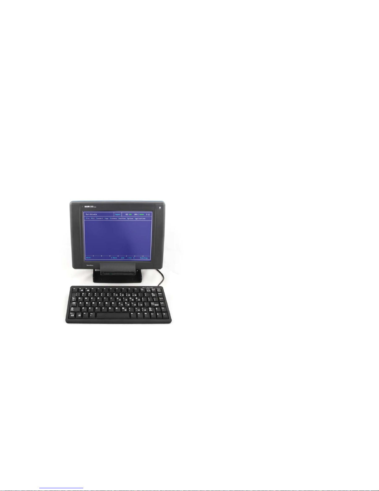
1 Installation
This chapter provides specific information about installation of the
TT-3606E Message Terminal and information about initial
inspection, storage and repacking for shipment.
Figure 1 TT-3606E Message Terminal
19Mar07 Page 1-1
Page 10

Installation Quick system connect and checkout
1.1 Quick system connect and checkout
The following brief outline may be used to get the TT-3606E
Message terminal up and running
• Unpack system components
• Connect the keyboard to the TT-3606E
• Connect a DC power source to the TT-3606E
The TT-3606E should then start the actual application program.
Please refer the manual for the specific application program.
Page 1-2 19Mar07
Page 11

Initial inspection Installation
1.2 Initial inspection
WARNING
To avoid hazardous electrical shock, do not perform electrical
tests if there is any sign of shipping damage to any portion of the
front or rear panel or the outer cover. Read the safety summary
at the front of this manual before installing or operating the
3606E Message Terminal.
Inspect the shipping carton immediately upon receipt for evidence of
mishandling during the transit. If the shipping carton is severely
damaged or water stained, request that the carrier's agent be
present when opening the carton. Save the carton packing material
for future use.
Contents of the shipment should be as listed in the enclosed packing
list. If the contents are incomplete, if there is mechanical damage or
defect, or if the 3606E Message Terminal does not work properly,
notify your dealer.
After you unpack the 3606E Message Terminal, inspect it thoroughly
for hidden damage and loose components or fittings.
Inspect the cable harness for stress, loose or broken wires, or
broken cable tires.
Examine all the components for loose or missing hardware.
Tighten all loose hardware.
19Mar07 Page 1-3
Page 12

Installation Storage
1.3 Storage
The 3606E may be stored or shipped in temperatures within the
limits -40° C to +80° C. It is advisable to protect 3606E from extreme
temperature variation which can cause excessive condensation. It is
recommended that the 3606E is unpacked immediately on delivery.
Page 1-4 19Mar07
Page 13

Repacking for shipment Installation
1.4 Repacking for shipment
The shipping carton for the 3606E has been carefully designed to
protect the Message Terminal and its accessories during shipment.
This carton and its associated packing material should be used
when repacking for shipment. Attach a tag indicating the type of
service required, return address, model number and full serial
number. Mark the carton FRAGILE to ensure careful handling.
If the original shipping carton is not available, the following general
instructions should be used for repacking with commercially
available material.
1. Wrap the 3606E in heavy paper or plastic. Attach a tag indicating
the type of service required, return address, model number and
full serial number.
2. Use a strong shipping container, e.g. a double walled carton of
160 kg test material.
3. Protect the front- and rear panel with cardboard and insert a 7
cm to 10 cm layer of shock absorbing material between all
surfaces of the equipment and the sides of the container.
4. Seal the shipping container securely.
5. Mark the shipping container FRAGILE to ensure careful
handling.
19Mar07 Page 1-5
Page 14

Installation Cabling
1.5 Cabling
For any installation it is required that all attached cables are shielded
and equipped with shielded connectors, which are properly
connected to the shield of the cable. Furthermore every shield
should have a low impedance connection to an electrical ground.
Before using the TT-3606E Message Terminal for the first time
check out that all cables are correctly wired and fastened.
Please notice that the DC-input range applies to the DC voltage
measured at the pin's on the power connector on the 3606E. This
means that the power cable characteristic should be taken into
account. The cable should allow the DC, measured at the input pin's
on the 3606E power connector, to stay within limits even though it
has to carry a current of 3 A.
Please notice, that the wires must be properly connected in the
connector and all pin’s for each power input must be connected to
the respective wire.
A cable using 2 mm2 (AWG 14) wire's of length 4 m fulfils the
requirements.
Please notice, that the cable connections must be properly installed.
Page 1-6 19Mar07
Page 15

Mounting Installation
1.6 Mounting
The TT-3606E Message Terminal may be mounted in several ways.
If the mounting bracket is not used, the TT-3606E Message
Terminal may be flush mounted in a consol by using the 4 screw
holes on the rear.
The mounting bracket may be used either to mount the TT-3606E
Message Terminal on a horizontal surface or a vertical surface. In
both cases the angle can be adjusted in steps of 7.5°. This is done
by loosening the hand wheels slightly and then move the upper part
of the TT-3606E Message Terminal into the wanted angle. Please
remember to tighten the handwheels again.
When assembling the mounting bracket together with the TT-3606E
Message Terminal it is important that the small indications on the
cylinders are in-line with the indications on the rear of TT-3606E
Message Terminal.
When installing the TT-3606E on a vertical surface it is necessary to
mount the mounting bracket opposite the way it is mounted for
horizontal installation.
Please refer to the chapter describing the detailed mechanical
outlines of the TT-3606E Message Terminal and mounting bracket.
19Mar07 Page 1-7
Page 16

Installation Mounting
This page is intentionally left blank
Page 1-8 19Mar07
Page 17

Mounting Description
2 Description
This chapter describes the TT-3606E Message Terminal. This
encompasses specifications as well as provides specific information
about the available features and interfaces.
19Mar07 Page 2-1
Page 18

Description Specifications
2.1 Specifications
Processor 386SX-40MHz
RAM 2 MB
Flash DISK 2 MB
Display 10.4” Color TFT flatpanel, 640x480
Floppy drive 3.5”
Keyboard i/f 5-pin mini-DIN
Parallel printer port 25 pin SubD female connector
Serial port COM1 9 pin SubD male connector, DTE type
Serial port COM2 9 pin SubD male connector, DTE type
Environmental Meets or exceeds all INMARSAT
specifications for the Inmarsat-C Network for
SOLAS with distress call functions. (CN114
and IEC 945 requirements). Meets CE-
marking requirements. Wheelmark approved.
Power Source 10 to 32 V floating DC, 15 pin SubD female
Power Consumption App. 20 Watts, maximum
App. 13 Watts, typical
Fuse Internal automatic recovering poly fuse
Ambient Temperature -20°C to 55°C operating
-40°C to 80°C storage.
Compass safe distance 50 cm
(measured in accordance with the standards
specified in ISO/R 694, Method B)
Dimensions H x W x D 221x 297 x 114.5 mm w/o bracket
256 x 297 x 114.5 mm w bracket at vertical
position
Weight 3.1 kg (including mounting bracket)
Table 1 TT-3606E Message Terminal
Page 2-2 19Mar07
Page 19

Connectors Description
2.2 Connectors
This section describes the functions and pin assignments of
connectors found on the rear of the TT-3606E. Figure 2 shows the
connector part of the TT-3606E Message Terminal.
Figure 2 Rear connectors
2.2.1 Keyboard connector
The figure below indicates the pin assignment of the keyboard
connector as seen from the rear of the TT-3606E Message
Terminal.
N/C
h
g
Clock
+5V
f
e
Ground
N/C
d
c
Data
Figure 3 Keyboard connector
19Mar07 Page 2-3
Page 20

Description Connectors
2.2.2 Power connector
The power input connector is a standard 15 pin SubD male
connector, located on the rear panel of the TT-3606E and the pin
assignments are as indicated below. The Remote ON/OFF input
makes it possible to place an eventual on/off switch at any location.
Pin Name Signal Description
1,2,9,10 + supply 10-32 VDC (Battery Positive input)
4,5,12,13 - supply DC Return (Battery Negative input)
6 Remote ON/OFF ON if connected to “- supply”
OFF if floating
7,8 SGND Chassis (Secondary GND)
Ground GND Shield
3,11,14,15 NC
Table 2 Power connector
Page 2-4 19Mar07
Page 21

Connectors Description
2.2.3 Parallel printer port
The parallel printer port is a standard 25 pin SubD female connector,
located on the rear panel of the TT-3606E and the pin assignments
are as indicated below.
Pin Name Signal Description
1 STRB Strobe
2 DAT0 Data Bit 0
3 DAT1 Data Bit 1
4 DAT2 Data Bit 2
5 DAT3 Data Bit 3
6 DAT4 Data Bit 4
7 DAT5 Data Bit 5
8 DAT6 Data Bit 6
9 DAT7 Data Bit 7
10 ACKN Acknowledge
11 BUSY Printer Busy
12 PE Paper End (out of paper)
13 SEL Printer Selected
14 ALFD Auto Line Feed
15 ERR Printer Error
16 INIT Initialise Printer
17 SLCT Select Printer
18 GND Ground
19 GND Ground
20 GND Ground
21 GND Ground
22 GND Ground
23 GND Ground
24 GND Ground
25 GND Ground
Table 3 Parallel port
19Mar07 Page 2-5
Page 22

Description Connectors
2.2.4 Serial ports
The serial ports are standard 9 pin SubD male connectors, located
on the rear panel of the TT-3606E and the pin assignments are as
indicated below.
Pin Name Direction Signal Description
1 DCD input Data Carrier Detect
2 RxD input Received Data
3 TxD output Transmitted Data
4 DTR output Data Terminal Ready
5 GND Ground
6 DSR input Data Set Ready
7 RTS output Request To Send
8 CTS input Clear To Send
9 RI input Ring Indicator
Table 4 Serial ports
The serial ports comply with the EIA/TIA-232 standard.
For full operating specifications for the serial interface, you are kindly
requested to refer to the CCITT Rec. V24 and the EIA/TIA-232
specifications.
To interface the TT-3606E to any DCE type of device such as for
example the TT-3020C Transceiver or TT-3616C Interconnection
box using a 1:1 RS-232 cable.
Page 2-6 19Mar07
Page 23

Disassembling Service
3 Service
This chapter describes how to disassemble and to service to a level
of changing boards/parts.
3.1 Disassembling
If you have to disassemble the TT-3606E Message Terminal it is
important, that you follow the procedure described in this section.
Otherwise you will find it very difficult and you risk to permanently
damage the Message Terminal.
WARNING
Do not try to disassemble the
TT-3606E Message Terminal
yourself.
This operation must only be
performed by qualified service
personnel.
The unit is assembled out of three parts:
1. Rear plate holding the floppy drive
2. Intermediate plate holding the different PCB’s on the rear side
and the flat panel on the front side.
3. Plastic front holding the display window.
19Mar07 Page 3-1
Page 24

Service Disassembling
To get access to the main PCB, backlight PCB (piggy bag on the
main PCB) and computer board the following steps should be
followed:
WARNING
To avoid hazardous electrical
shock, do not touch the two
high voltage outputs of the
backlight inverter.
1. Make sure the mounting bracket is removed
2. Unscrew the 12 counter sunk screws on the rear and the 8 SubD stays.
3. Gently divide the front part and rear part from each other so that
the flex cable connecting the floppy with the main PCB on the
intermediate plate can be removed by releasing the zeroinsertion force cable connector mounted on the main PCB (J15).
If it is necessary to remove/replace the main PCB it is necessary to
remove the backlight inverter first in order to get access to two of
the screws holding the main PCB.
Page 3-2 19Mar07
Page 25

Configuration Service
3.2 Configuration
The main PCB, which is shown in figure 4, contains the following
jumpers, measurement points and adjustment possibilities:
Reference Factory setting or
value/range
Function
W1 Open If closed the computer is
reset
W2 Closed Connecting/disconnecting
power supply from rest of
circuitry
W3 120 kHz, ± 2 kHz Switch frequency of switch
mode power supply
W4 Pin 2 and 3 closed Select 3606 XP/E backlight
TP1 0 - 3.6 V DC Output of light sensor
R38 120 kHz, ± 2 kHz Adjustment of switch
frequency
Table 5 Configuration
The jumper W2 can be used to remove the connection between the
switch mode power supply and the rest of the circuitry including
computer as well as backlight inverter. The pin assignments for W2
are as follows. Please notice that ground connection can only be
disconnected when the PCB is NOT mounted on the intermediate
plate.
19Mar07 Page 3-3
Page 26

Service Configuration
W2 pin no Function
1 2 + 12 V DC, ± 20 %
3 4
5 6 Ground
7 8
9 10
11 12
13 14 + 5 V DC, ± 10 %
15 16
17 18 No Connection
19 20
Table 6 Jumper W2
The CMOS-setup in the computer may be reset to default by moving
the jumper marked “CLEAR CMOS” on the computer board from
position 1-2 to position 2-3 and then back to position 1-2.
Page 3-4 19Mar07
Page 27

Configuration Service
Figure 4 Main PCB
19Mar07 Page 3-5
Page 28

Service Configuration
This page is intentionally left blank
Page 3-6 19Mar07
Page 29

Detailed specification Technical description
4 Technical description
This chapter gives a detailed description of the TT-3606E Message
Terminal.
4.1 Detailed specification
The hardware platform of TT-3606E Message Terminal is PC compatible. The table below gives a more detailed specification of
the computer part. Whether or not these hardware features are used
dependents on the installed application program.
Processor 386SX-40MHz
Data bus 16-bit
Processing ability 32-bit
Shadow RAM Support for system and video BIOS up to
256 kB in 32 kB blocks
Display memory 512 kB DRAM
IDE HDD interface Supports up to two IDE (AT bus) HDD’s
FDD interface Supports up to two FDDs
Parallel port Bi-directional (SPP/ECP/EPP modes)
Serial ports Two RS-232 (both use 16C550 UART with
16-byte FIFO). Up to 115.200 baud.
Real time clock ALI M6117B internal RTC, battery for up to
10 years data retention
DMA channels 7
Interrupt levels 15
Keyboard interface PS/2
Bus speed 8 MHz
Flash DISK DiskOnChip2000 from M-Systems.
Address: DC000-DDFFF
Table 7 Detailed specification
19Mar07 Page 4-1
Page 30

Technical description Detailed specification
Figure 5 shows the physical outline of the computer board:
Figure 5 Computer board
Page 4-2 19Mar07
Page 31

Special I/O Technical description
4.2 Special I/O
Special I/O ports have been implemented in the TT-3606E Message
Terminal in order to be able to support some extra features
compared to a standard PC. These are
• Disk change signal from floppy
• Backlight control of TFT flat-panel
• Watchdog
• Light sensor
• Reset of external keyboard
The table below indicates the diffent I/O ports
Address Direction Function
302h output light sensor sample and hold
302h input light sensor output
303h output control of
display backlight level
watch dog
keyboard reset
Table 8 Special I/O ports
The light level surrounding the equipment is determined by the light
sensor circuitry. A sample/hold of the light level is done by writing to
this port two times. The sampled value can then be determined by
reading this port afterwards.
An 8-bit A/D-converter is used with a reference level of 5V
(corresponds to A/D value FFh). The linear light sensor gives an
output in the range from 0V to 3,60V, thus the light level is in the
range from 00h to approximately C0h (255*5V/3,75V).
The tables below indicate the precise function of each bit in the
remaining ports.
19Mar07 Page 4-3
Page 32

Technical description Special I/O
The “disk change signal “ is a hardware signal from the floppy drive
which during access to the floppy indicates (goes to 0) whether or
not the floppy has been changed. Can be used in the application
software to only read the FAT-table, when the floppy has actual
changed.
303h Function
0 (LSB) If 0 display backlight off else on
1 N/A
2 N/A
3 If toggled from 1 to 0 to 1 the light level of the
selected backlight(s) is(are) changed 1 unit (out of
100), /INC. Direction depends on bit 4
4 If 0 the light level is decreased when toggeling bit 3
(/DWN) else increased
5 Watch dog toggled when changing this bit
6 If 0 watchdog is disabled else enabled
7 (MSB) External keyboard enabled if 0 and disabled/reset if
1
Table 9 Control port (all 0 except bit 1,2 after power up)
The control port is used to set/reset the different bits in the
connected register. After power up all bits in this register defaults to
“0” except bit 1 and 2 which set to 1. This implies that the the display
backlight is turned on, the watchdog is disabled and the external
keyboard is enabled.
After the unit has booted, the application can enable the watchdog, if
the application program supports a watchdog surveillance circuitry. If
enabled it must be toggled every 0,5 second by changing the
appropriate bit as indicated above otherwise the unit will reset and
reboot.
Page 4-4 19Mar07
Page 33

Special I/O Technical description
The reset possibility of the external keyboard can be used by the
application software for keyboard surveillance purposes.
The display backlight is controlled using electronic potentiometers
controlled using three signals:
CS : Chip Select
/INC: Increment
/DWN: Up/down selection
If CS is “1” the electronic potentiometer is selected and the /INC and
/DWN signals can be used to adjust the electronic potentiometer and
thus the light level. If CS is “0” these two signals will not imply any
change. Every time the /INC-bit is toggled the potentiometer is
adjusted 1/100 of its maximum value. The direction is controlled by
the /DWN-bit. If it is 0 the light level is decreased where as a 1 will
imply an increase when the /INC bit is toggled.
In this way the application can control the potentiometers to obtain
any of its 100 different positions/levels.
The /INC bit may not be changed more often than every 4 µsec.
Both potentiometers can be adjusted simultaneously in the same
direction by setting both CS bits to “1”.
To make sure that the position of the potentiometers are known by
the application software after power up both potentiometers should
be initialised with 100 pulses in either up or down. It is
recommended to decrease both backlights to the minimum level at
power up.
With respect to the display backlight there is a 1:1 relation from
potentiometer position 100 (maximum light) down to approximately
60. Below 60 the display backlight level will not change.
19Mar07 Page 4-5
Page 34

Technical description Special I/O
In order to completely turn off the backlight it is necessary to use the
display backlight on/off bit and set it to 1.
A way to cope with the display backlight characteristic is to have two
display setups/styles: one used during daylight (bright colors, but not
red) and one used during night (red characters and graphics on a
black background).
Page 4-6 19Mar07
Page 35

Special I/O Technical description
This page is intentionally left blank
19Mar07 Page 4-7
Page 36

Page 37

Index
5 Mechanical outlines
This chapter shows the dimensions of the TT-3606E Message
Terminal as well as the mounting stencils for the different ways of
mounting the TT-3606E Message Terminal.
5.1 TT-3606E
Figure 6 and 7 shows the dimensions of the TT-3606E Message
Terminal.
Figure 6 TT-3606E Message Terminal
19Mar07 Page 5-1
Page 38

Mechanical outlines
Figure 7 TT-3606E Message Terminal
Page 5-2 19Mar07
Page 39

Index
5.2 Flush mount
Figure 8 indicates the dimension of the panel cut-out and position of
mounting holes when mounting the TT-3606E Message Terminal in
a consol.
Figure 8 TT-3606E Message Terminal
19Mar07 Page 5-3
Page 40

Mechanical outlines
5.3 Mounting bracket
Figure 9 indicates the position of the mounting holes for the
mounting bracket.
Figure 9 TT-3606E Message Terminal
Page 5-4 19Mar07
 Loading...