

Thrane&Thrane sailor 60, sailor 90, SAILOR 90 Satellite TV World, TT-3055B, TT-3057A Installation Manual
Page 1

i
SAILOR 60 Satellite TV Antenna
INSTALLATION MANUAL
Page 2

ii
SAILOR Satellite TV Antenna
Installation and maintenance manual
SAILOR 60 satellite TV antenna including
Above Deck Unit TT-3054B and Antenna Control Unit TT-3057A
Page 3

iii
Disclaimer:Disclaimer:
Disclaimer:Disclaimer:
Disclaimer:
Any responsibility or liability for loss or damage in connection with the use of this
product and the accompanying documentation is disclaimed by Thrane & Thrane. The
information in this manual is provided for information purposes only, is subject to
change without notice and may contain errors or inaccuracies.
Manuals issued by Thrane & Thrane are periodically revised and updated. Anyone
relying on this information should acquire the most current version e.g. from the
Thrane & Thrane Extranet at http://extranet.thrane.com.
Thrane & Thrane is not responsible for the content or accuracy of any translations or
reproductions, in whole or in part, of this manual from any other source.
Page 4

iv
Page 5

v
TT
TT
T
able of Cable of C
able of Cable of C
able of C
onon
onon
on
tt
tt
t
enen
enen
en
tt
tt
t
ss
ss
s
Chapter 1Chapter 1
Chapter 1Chapter 1
Chapter 1
GenerGener
GenerGener
Gener
al al
al al
al
inin
inin
in
ff
ff
f
oror
oror
or
mm
mm
m
atat
atat
at
ii
ii
i
onon
onon
on
Satellite TV reception, general information, footprints ...........................1
Chapter 2Chapter 2
Chapter 2Chapter 2
Chapter 2
Functional descriptionFunctional description
Functional descriptionFunctional description
Functional description
Description of operation ..................................................................... 6
Calibration ........................................................................................ 6
Satellite search ................................................................................. 6
Tracking............................................................................................ 7
Satellite identification ........................................................................ 7
Polarisation control ........................................................................... 9
Chapter 3Chapter 3
Chapter 3Chapter 3
Chapter 3
InstallationInstallation
InstallationInstallation
Installation
Antenna location .............................................................................. 10
Mounting......................................................................................... 12
Connections ..................................................................................... 13
SAILOR 60 pedestal mounting ........................................................... 15
Radome cable wiring ........................................................................ 17
Control unit connection .................................................................... 20
Choice of tracking and ID-receiver signals .......................................... 21
Alignment of heading indicator .......................................................... 21
Obscured sectors ............................................................................. 22
Start-up procedure ......................................................................... 22
Chapter 4Chapter 4
Chapter 4Chapter 4
Chapter 4
OperOper
OperOper
Oper
atat
atat
at
ii
ii
i
onon
onon
on
Normal use .................................................................................... 23
Menus............................................................................................ 23
Special functions ............................................................................. 23
Page 6

vi
Table of Contents
Chapter 5Chapter 5
Chapter 5Chapter 5
Chapter 5
PP
PP
P
CC
CC
C
pr pr
pr pr
pr
oo
oo
o
grgr
grgr
gr
am, mam, m
am, mam, m
am, m
aa
aa
a
inin
inin
in
tata
tata
ta
inin
inin
in
ing NID-tableing NID-table
ing NID-tableing NID-table
ing NID-table
ss
ss
s
PC software installation .................................................................... 27
Main menu ...................................................................................... 31
Service menu .................................................................................. 32
Calibration menu ............................................................................. 33
Conical scan menu .......................................................................... 34
Log menu ....................................................................................... 34
Satellite menu ................................................................................. 35
Satellite identification menu ............................................................. 36
NID-tables ...................................................................................... 37
Antenna program update .................................................................. 41
Chapter 6Chapter 6
Chapter 6Chapter 6
Chapter 6
SerSer
SerSer
Ser
vv
vv
v
icic
icic
ic
ee
ee
e
, mec, mec
, mec, mec
, mec
hh
hh
h
anan
anan
an
icic
icic
ic
al dral dr
al dral dr
al dr
aa
aa
a
ww
ww
w
inging
inging
ing
ss
ss
s
Service and repair ........................................................................... 43
Replacing CPU ................................................................................. 44
Replacing IMU ................................................................................ 45
Replacing LNB ................................................................................ 46
Replacing elevation motor belt ......................................................... 47
Replacing elevation motor ............................................................... 48
Replacing azimuth motor belt .......................................................... 49
Replacing azimuth motor ................................................................. 49
Replacing polarisation motor ........................................................... 50
Replacing polarisation motor belt ..................................................... 50
Replacing RG179 coaxial connectors .................................................. 51
Chapter 7Chapter 7
Chapter 7Chapter 7
Chapter 7
TT
TT
T
rr
rr
r
oubleouble
oubleouble
ouble
shootshoot
shootshoot
shoot
inging
inging
ing
Error codes ..................................................................................... 52
Troubleshooting chart ...................................................................... 53
Chapter 8Chapter 8
Chapter 8Chapter 8
Chapter 8
TT
TT
T
ecec
ecec
ec
hnhn
hnhn
hn
icic
icic
ic
al specifal specif
al specifal specif
al specif
icic
icic
ic
atat
atat
at
ii
ii
i
onon
onon
on
SAILOR 60 satellite TV antenna ........................................................ 54
Chapter 9Chapter 9
Chapter 9Chapter 9
Chapter 9 Approvals ....................................................................................... 56
Page 7
1
Chapter 1
System Units
General information
Satellite TV reception, general information, footprints
Satellite orbits
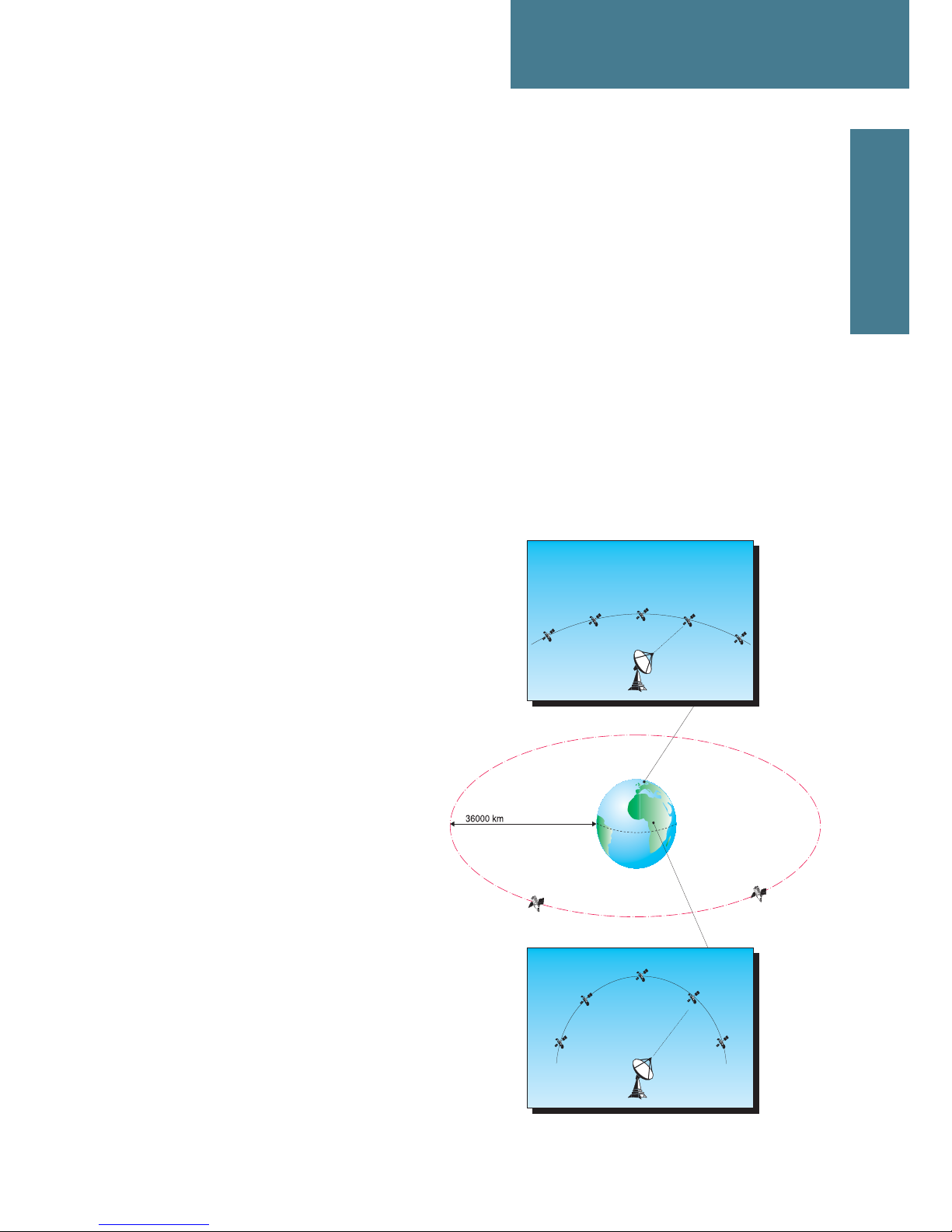
All TV-satellites move in so called geostationary orbit 36.000 km above the
Earth's equator. At this specific altitude their angular velocity matches the
Earth's exactly and make them appear motionless in the sky.
When viewed from the northern hemisphere the satellites appear along an arch
with the satellite due south at the top.
The necessary separation between satellites depends on the frequency and the
size of the antennas and is usually 3°. A large number of satellites can be colocated in the same position as long as
they transmit on different frequencies.
Co-located satellites are allowed to
deviate 0,1 degrees within their position,
which equals to a cube with a side of 73
km. At position 19.2 deg East (Astra 1) for
instance, there are actually 5 satellites
within the same position.
The satellites get their signals from an
uplink station. The satellite that
receives the signal shifts the
frequency down to about 1012 GHz, amplifies it and
transmits it back towards
earth by what is called
transponders. The satellites
electrical power comes from solar
panels, and the satellite is kept in
position by small jet-motors mastered
by ground-control. The actual life-span
of a satellite mainly depends on fuel
left for positioning jets.
Page 8

2
Chapter 1: General information
Antenna and LNB
Transponders
TV-satellites that can be viewed with Satellite antennas transmit in the Ku frequency
band on frequencies between 10.700 and 12.750 MHz. Each satellite typically has
several transmitters or transponders that carry a number of digital TV and/or radio
channels.
Antenna and LNB
When the signals reach the antenna they are focused by the dish and radiated into
the feedhorn and passed along to the LNB (Low Noise Block converter). The LNB
amplifies the signals and transforms them to a lower frequency within the so-called
satellite IF-band. Satellite receivers use the IF band which covers 950-2150 MHz
(2300 MHz in some areas).
Since the Ku-band covers 2050 MHz and the IF-band only 1200 MHz, it is necessary
to divide the incoming signals into a high band and a low band with separate outputs
on the LNB. Low-band IF-signals are shifted 9750 MHz down and high-band IFsignals 10600 MHz down.
Page 9
3
Polarisation
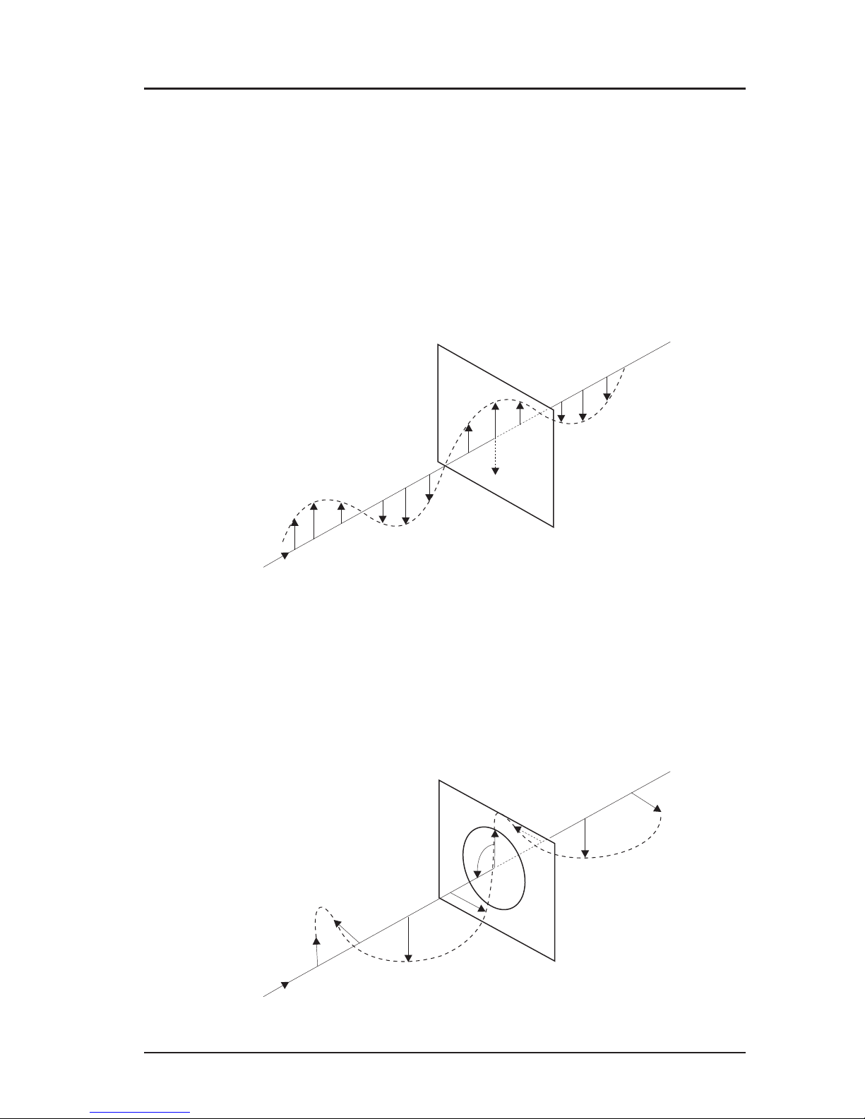
In order to increase the number of channels in each satellite slot the signals are
transmitted with different polarisation. Two kinds of polarisation are used in TV
transmissions: linear and circular.
Linearly polarised signals propagate with their wavefronts aligned either horizontally
or vertically. The receiving LNB can then separate the two polarisations if it is aligned
properly.
Circularly polarised signals propagate with their wavefronts rotating either clockwise
or counter-clockwise
The main advantage with linear polarisation over circular is that the isolation between
the two modes is better. The main advantage with circular polarisation is that the
feedhorn doesn't need to be aligned.
Chapter 1: General information
Polarisation
Page 10
4
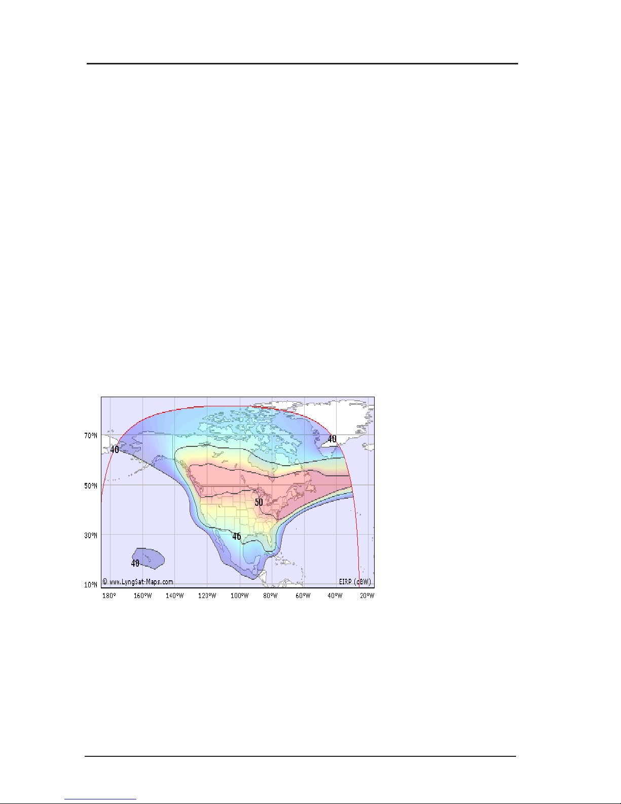
Footprints
The satellite footprint is a map showing a satellite’s fieldstrength or EIRP
(Effective Isotopic Radiated Power). It's not a real unit, but more a practical
model you can use when you graphically view the radiated area.
Every satellite has it's own footprint, and by consulting the footprints and the
conversion table you can estimate the antenna size needed.
One satellite can transmit several beams, where every beam has it's own
footprint and content regarding channels and service providers.
For updated information regarding footprints, frequencies, service providers etc.
we recommend you to consult websites such as www.lyngsat.com,
www.satbeam.com or www.kingofsat.net.
Below you can see a few typical footprints Anik F1R (W107,3), Astra 1H (E28,2)
and NSS6 (E95,0)
Chapter 1: General information
Footprints
Anik F1R Ku band
EIRP
(dBW)
>50
50
49
48
47
46
45
44
43
42
41
40
39
38
37
36
35
34
33
Page 11
5
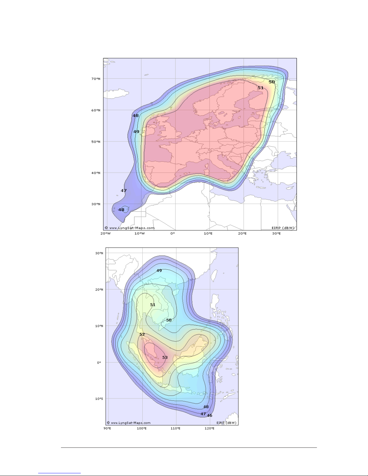
Footprints
Astra 1H
NSS 6
Ku band
EIRP
(dBW)
>50
50
49
48
47
46
45
44
43
42
41
40
39
38
37
36
35
34
33
Page 12

6
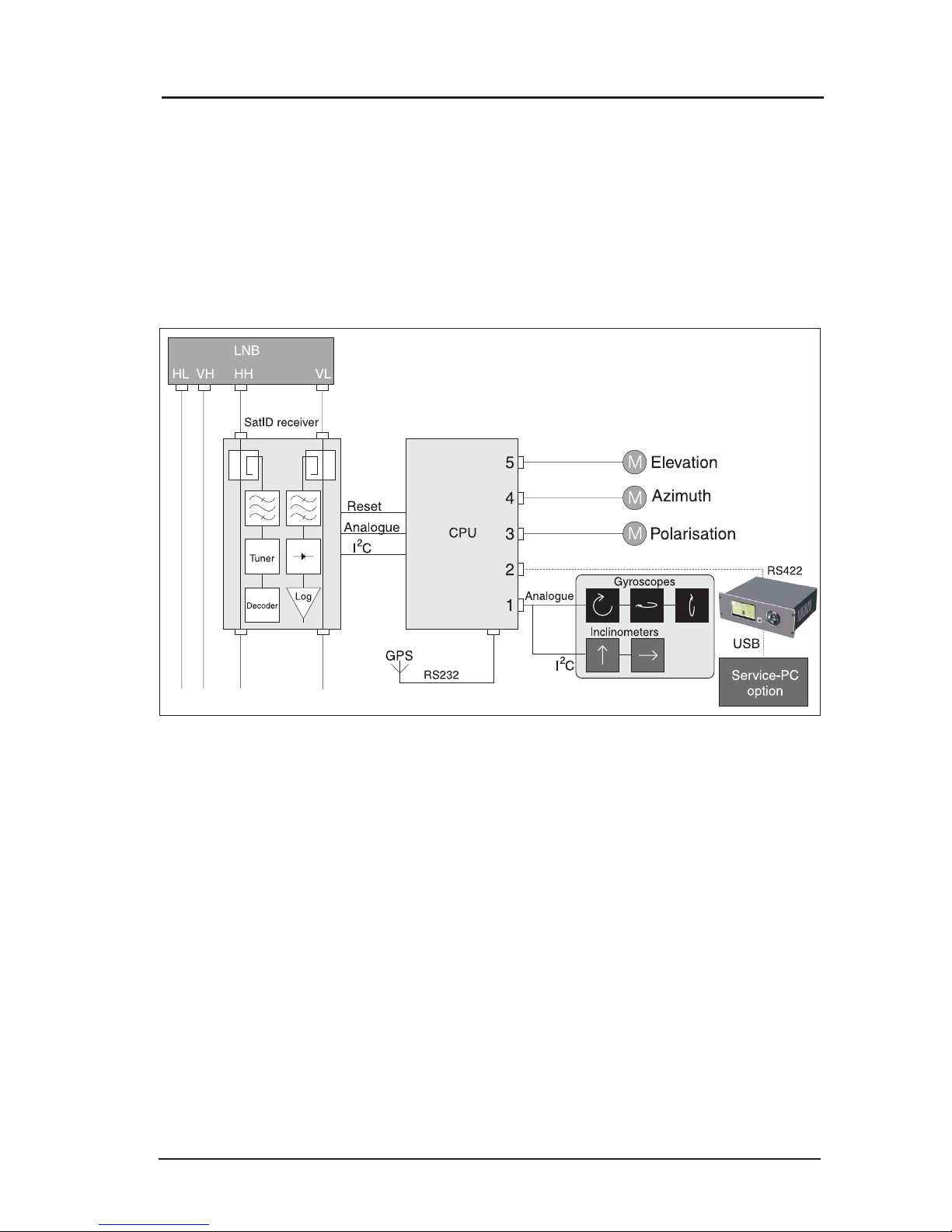
Functional description
Description of operation
After power-up, the antenna performs a self-test and calibration lasting up to five
minutes. It then enters search mode and starts searching for a satellite. The antenna
automatically calculates the elevation of the selected satellite using a built-in GPSreceiver to determine the current position1.
After locking on a satellite, the ID-receiver attempts to identify it and repositions the
antenna if necessary. Polarisation is adjusted automatically when a satellite is
identified.
For a more detailed explanation a satellite identification see sections satellite ID and
satellite ID menu
Calibration
Polarotor turns to counter clockwise mechanical end stop (seen from behind)
Elevation goes down to mechanical end stop
Azimuth turns to counter clockwise mechanical end stop
Elevation goes up then down (test of elevation gyro)
Azimuth goes clockwise-counter clockwise (test of azimuth gyro)
Elevation goes up to 90 degrees (test of inclinometer)
Antenna makes a 45 degree clockwise sweep
Antenna makes a counter clockwise noise sample sweep
After this it goes into search mode, trying to locate a satellite
Satellite search
Two search patterns are used. The large pattern is used when no information is known
about the satellite positions. The antenna then moves in full circles at different
elevation angles. The small pattern is used to reacquire a satellite after loss of
tracking.
If the default tracking mode (Auto) is set in the SatID-menu then the search is made
with a signal detector that receives signals from a selectable part of the satellite IFband.
Chapter 2
Functional description
1
If the antenna has been switched off for a long time, the GPS-receiver may take
up to 20 minutes to initiate. It may then be necessary to enter the ship's position
manually in the service menu.
Page 13

7
In some circumstances it can be useful to carry out the
search using the tuner - the Tuner Tracking Mode.
The antenna will then only lock on a satellite
transmitting a DVB-S signal on the preset frequency
with a certain symbol rate and FEC. These settings are
available from the PC-program only.
Tracking
When the signal level exceeds the threshold level during a search, tracking is
initiated. The antenna then uses a combination of gyroscopes and dish scan to keep
it pointed at the satellite.
The dish scan continuously rotates the antenna in a small angle around its aiming
point to correct for gyroscope drift. The signal is monitored either with a tuner set to
a specific frequency or with a signal detector via a bandpass filter. See section
Tracking mode
Signals from two of the four LNB outputs are tapped off and one fed to the tuner and
the other to the detector. Vertical low is the default LNB output for the detector and
horizontal high for the SatID.
Satellite identification
After locking on a satellite the ID-receiver attempts to identify it by matching the
transponder's network identifier code or NID with the antenna's internal list.
If the identified satellite is another one than selected, the correct position is
calculated and the antenna automatically repositioned. When a correct match is
made, "Confirmed" is written after the satellite name in the display.
Please see section Network IDs.
If the satellite remains unidentified, the antenna tries to acquire another
satellite.
Chapter 2: Functional description
Satellite identification
Page 14

8
Satellite identification
After identification polarisation is adjusted to match the satellite.
The angles are calculated based on the ship's position and the satellite's longitude
assuming a 0° angle in locations on the same longitude. Compensation for
ship´s movements is also performed continuously.
As some satellite’s polarisation is offset, a provision is made to fine-tune it in the SatID
menu of the PC-program.
Page 15
9
Polarisation control
During initial NID-scanning, polarisation is set to 0°. If no identification is made, scans
are executed on -15° and 15° as well.
If the satellite remains unidentified, the antenna tries to acquire another satellite.
Chapter 2: Functional description
Polarisation control
Page 16
10
Chapter 3
Installation
Installation
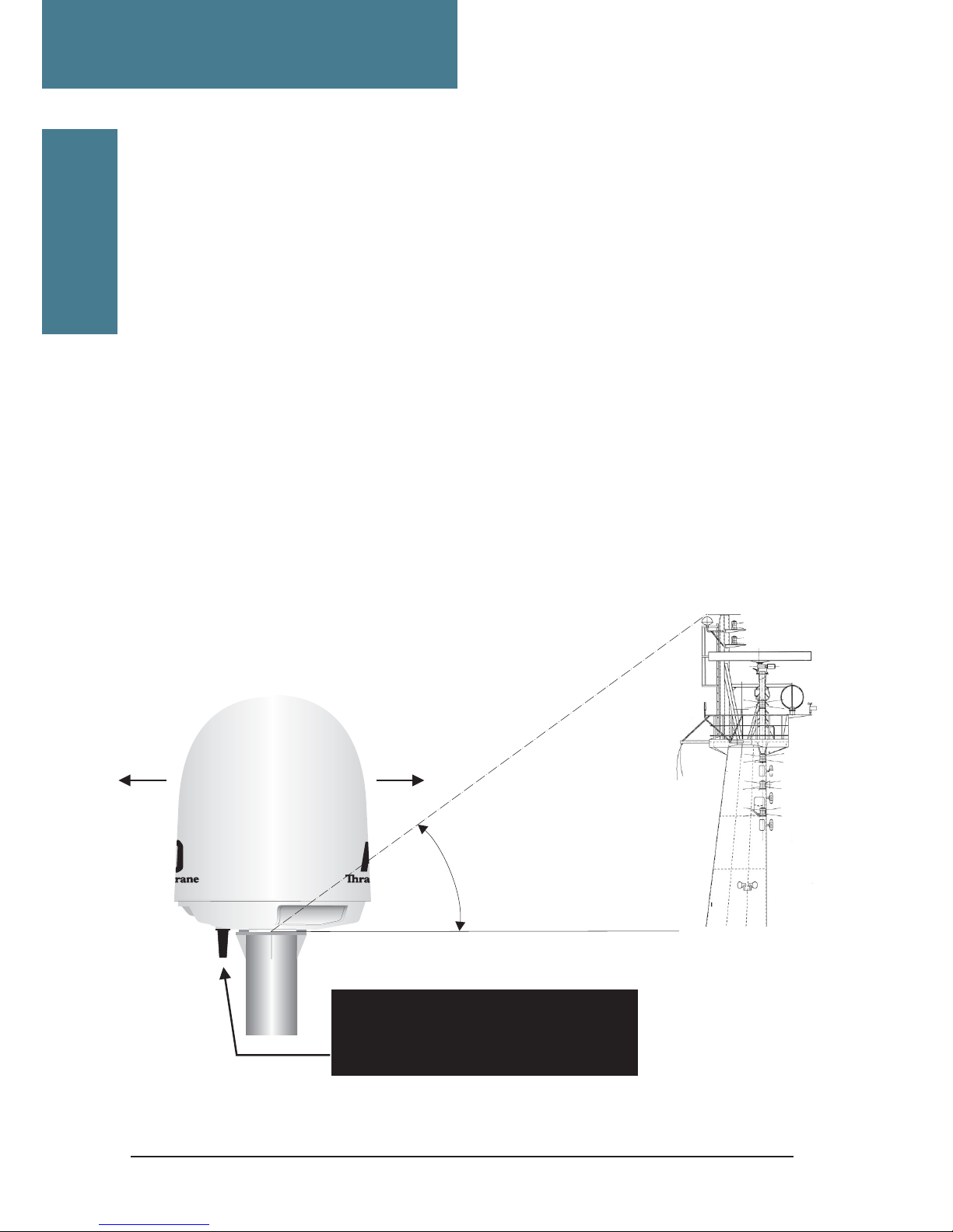
Antenna location
Choose a location that has an unhindered view of the satellite at the point of lowest
elevation. Ideally, a location should be chosen as close to the vessel's centre as
possible while keeping cable lengths to a minimum.
If the antenna is placed on a pedestal, care must be taken that it does not flex
or vibrate.
The satellite TV antenna's LNB is equipped with a radar filter but to avoid damage
to the LNB it is strongly advised that it should not be placed in the path of a radar beam.
It must not be placed in the path of a VSAT antenna.
Installation
RS
®
Obstacle
BOW
NOTE! VERY IMPORTANT
STERN
Drainage tube,
shall be mounted facing rear
end of ship/vessel (stern).
Page 17
11
Installation
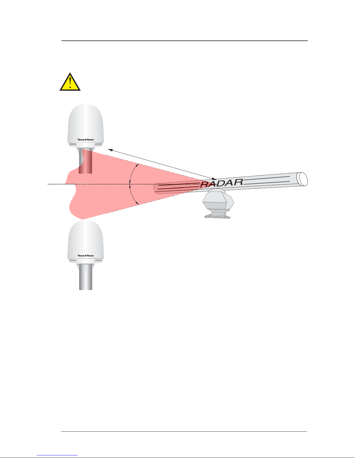
Radar
It is difficult to give exact guidelines for the minimum distance between a radar and
the antenna because radar power, radiation pattern, frequency and pulse length/
shape vary from radar to radar. Further, the antenna is typically placed in the near
field of the radar antenna and reflections from masts, decks and other items in the
vicinity of the radar are different from ship to ship.
However, it is possible to give a few guidelines:
Since a radar radiates a fan beam with horizontal beam width of a few degrees and
vertical beam width of up to +/- 15o, the worst interference can be avoid by mounting
the satellite TV antenna at a different level - meaning that the antenna is installed
minimum 20o above or below the radar antenna. Due to near field effects the benefit
of this vertical separation could be reduced at short distance (below approx. 10 m)
between radar antenna and satellite TV antenna. Therefore it is recommended to
ensure as much vertical separation as possible when the satellite TV antenna has
to be placed close to a radar antenna.
SAILOR
®
SAILOR
®
The satellite TV antenna must be mounted as far away as possible from ship’s
radar and high power radio transmitters (including Inmarsat based systems),
because they may compromise the antenna performance. RF emission from radars
might actually damage the satellite TV antenna.
Preferred placing
Avoid if possible
Min 20
o
d
Min 20
o
Chapter 3: Installation
Page 18
12
Installation
Mounting
Rigid mounting is essential for proper function and parts of the vessel subject to heavy
resonant vibrations are unsuitable for satellite TV antenna installation.
If pedestals higher than 1 m are used utmost care must be taken to ensure rigidity and
that the natural frequency of the pedestal/satellite TV antenna is as high as possible.
Mounting bolts should be tightened with a torque of 20 Nm, and medium or permanent
strength thread-locking fluid applied.
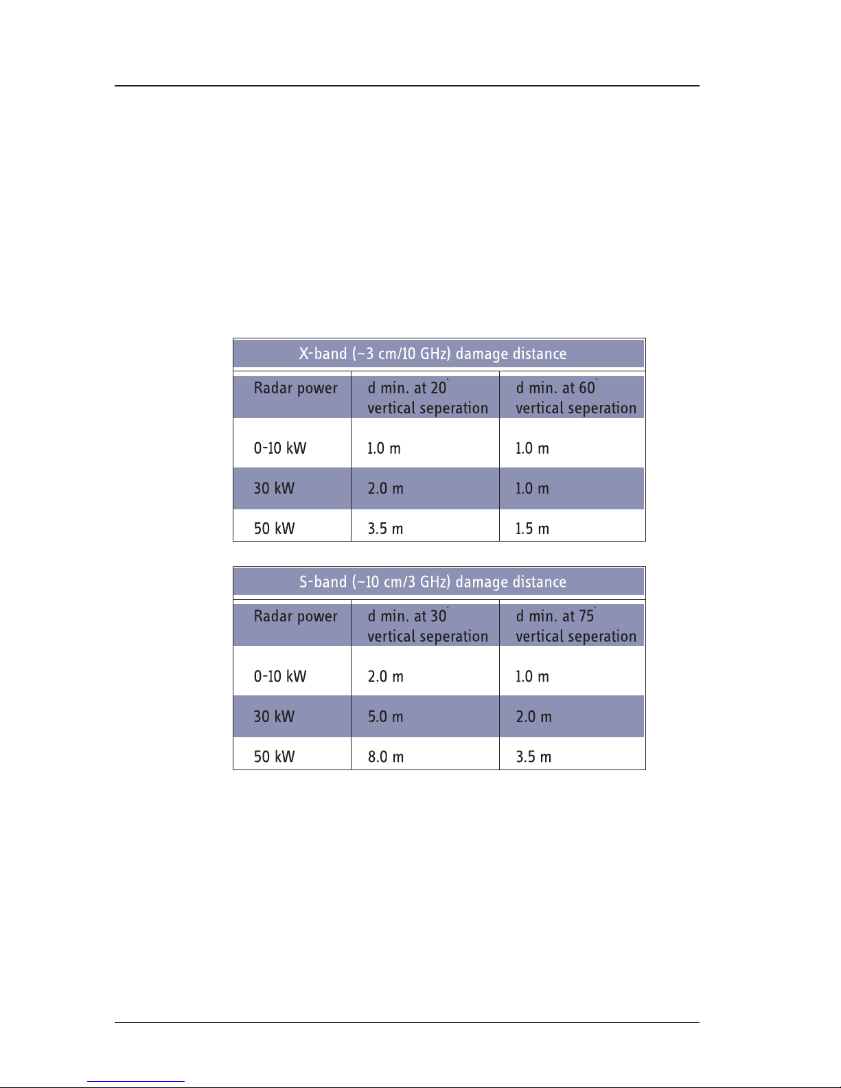
The minimum acceptable seperation (d min.) between a radar and the satellite TV
antenna is determined by the radar wavelength/frequency and the power emitted by
the radar. The tables below show some “rule of thumb” minimum separation
distances as a function of radar power at X and S band. If the d min. separation listed
below is applied, antenna damage is normaly avoided. “d min.” is defined as the
shortest distance between the radar antenna (in any position) and the surface of the
satellite TV antenna.
Radar distance
Compass Safe DistanceCompass Safe Distance
Compass Safe DistanceCompass Safe Distance
Compass Safe Distance: 1 m
Chapter 3: Installation
Page 19
13
Connections
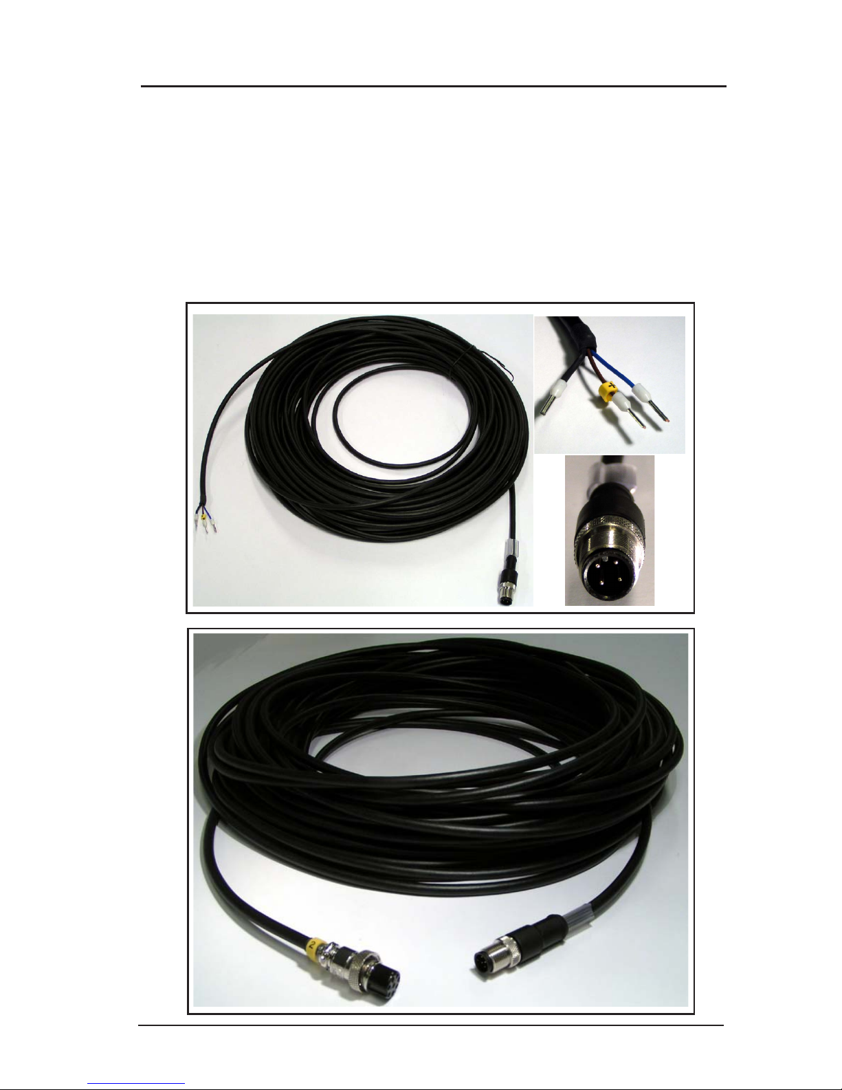
Three kinds of electrical connections are to be made during installation:
1. Power supply 24 V DC, min 5 A, 2 poles. Use prefabricated 25m cable enclosed
in this antenna packaging (se pic 1 below).
2. Control unit, 7 poles + shield, use prefabricated 25m cable (se pic2 below).
3. Four coaxial cables, cables to be marked with ”1”, ”2”, ”3” and ”4”
Chapter 3: Installation
SAILOR 60 pedestal mounting
picture 1
picture 2
Page 20

14
Chapter 3: Installation
SAILOR 60 pedestal mounting
F-splicer socket
Vulcanizing tape
Crimp F-connector for 7 mm coax type
TELASS 110: (KTV 1.1/4.9 CV)
Crimp F-connector for 10 mm coax type RG11 or
75160AF: B004, PPC-Denmark
Cable splicing
For installtions 25 metres and below between satellite TV antenna and satellite
receiver a thinner type of 7 mm:s low loss cable can be used.
For example TELASS 100 or TELASS 110 (KTV1 1/4.9 CV).
For more information regarding these cables please visit
www.coferro.dk
www.bedea.com/pdf/breitband/BK2004_18%2B19
For installations exceeding 25 metres between satellite TV antenna and receiver
a thicker low loss cable must be used.
For example 75160AF or Coax 6. For more information regarding this type
of cable please visit www.belden.com
NOTE: Maximum loss between satellite TV antenna and SAT-receiver 15 dB
Page 21

15
SAILOR 60 deck mounted pedestal example
Satellite TV antenna weight including radome: 49 kg
SAILOR 60 pedestal mounting
VERY IMPORTANT!
Stability calculations (if required)
is owner/shipyard responsibilty
Radomemont-60-A5.CDR
5.0
105.0
66
Tube thickness
min 5 mm
175.0
500-1000
817
687
Bow view
All measurements in mm
8x
4x
4x
10.0
O190
O325
Vessel
Drainage
hole
Rubber drainage tube.
SAILOR
®
Page 22

16
SAILOR 60 deck mounted pedestal example
SAILOR 60 pedestal mounting
O 11.0 (4x)
O 100
200.0
200.0
45
o
Reinforcement
(8x)
VERY IMPORTANT
The satellite TV antenna must be mounted on the pedestal using
and thread locking fluid applied.
The length of the bolts must be such that they engage into the bushings of the
radome with minimum 10 mm and maximum 15 mm.
all 4
M10x20 hex bolts
Radomemont-60-1-A5.CDR
Page 23

17
Radome cable wiring
Chapter 3: Installation
Radome cable wiring
Filterbox
power supply
Shield connection
Female F-connector bulkhead jack
Power supply
connector
ACU
connector
Page 24

18
Chapter 3: Installation
Radome cable wiring
Radome cable wiring
Drainage tube
Stainless
Self tapping
screws (4x)
12x3.5 mm
1
VH
2
VL
3
HL
4
HH
1
2
3
4
Multi switch (option)
Sat reciever
Sat reciever
Sat reciever
Sat reciever
Page 25

19
Cable fixing
Cables shall be fixated with 2 pcs of 368x5 mm cable tie
Use only prescribed tools to strip and
crimp coax cable with F-connector.
TELASS KTV 1.1/4.9 CV
TELASS KTV 1.1/4.9 CV
TELASS KTV 1.1/4.9 CV
7 mm
1 mm
F-connector crimp 1.1/4.9
F-female
Use enclosed shrinking tube
with glue to make a
waterproof connection
Use die cast .319” size to crimp
Chapter 3: Installation
Radome cable wiring
Page 26

20
Chapter 3: Installation
Control unit connection
Control unit connection
Control unit can be mounted with M3 screws after removing rubber pads.
Screws should not extend more than 6 mm inside chassis.
See next page for
cable specification
200
208
O4.5
61.5
69.5
44
163
Fixed mounting of control unit
Bottom view
164.5
105.0
M3 (4x)
PowerFuse
T160 mAL
Antenna
Rear panel on control unit
8-pin
NOTE! Secure all cables
inside pedestal
24V DC
25m
25m
To PSU power
supply +24V DC
To Control unit
PLT
Page 27

21
Choice of tracking and ID-receiver signals
The default connections are horizontal high (HH) to the ID-receiver and vertical low
(VL) to the signal detector. The signal detector can be connected to any LNB output
however (as long as it's not used by the ID-receiver). Another output than the default
can be used to increase the signal-to-noise ratio on a specific satellite.
If the output for the ID-receiver is changed, a corresponding NID-table must be
loaded. See section Satellite identification
Alignment of heading indicator
If the satellite TV antenna is aligned with the ship's bow direction in the CCW endstop, the heading indicator's offset is zero.
If the antenna is positioned otherwise, the offset can be entered in the service menu.
See section Service menu
Chapter 3: Installation
Alignment of heading indicator
PLT
25 metres
25 metres
Shield/black shrink tube
M12 connector IP67
8x0.25mm
Binder male cable
No: 79 5066 xxx 08
2
M12 connector IP67
4x0.34mm
Binder male cable
No: 79 5401 xxx 04
2
Pinout
Pinout
a (+24V DC)
1 (R422-)
4 (T422-)
6 (T422+)
7 (R422+)
3 (GND com)
2 (GND 24V)
5 (NC)
Chassi
1
2
3
4
Chassi
Red
White
Yellow
Pink
Blue
Green
Brown
Grey
Shield
Brown, +24 V
NC
Blue, GND
NC
Shield
22
+
“ Cable CPU - ACU”
“ Cable power supply”
Pinout
1
2
3
4
5
6
7
8
Red
Brown
Pink
Yellow
Green
Blue
White
Grey
+24 V
GND 24V
T422+
T422GND
R422+
R422NC
2
3
4
1
Red
Brown (+)
Black
Blue (GND)
White
Front view
7
1
2
a
5
3
6
Grey
Yellow
Green
Brown
Pink
Blue
White
4
NOTE:View front side
Page 28

22
Obscured sectors
A fixed object that obscures the satellite TV antenna not only precludes reception but
can also cause strong reflections. To prevent the satellite TV antenna from locking
on such signals, obscured sectors can be programmed in the calibration section of
the service menu. See chapter 5.
Start-up procedure
1. If a satellite list with NID-codes is not preinstalled, see section 5.
2. Power up and choose a satellite from the list.
3. If GPS is not yet active, set position.
SERVICE SERVICE
SERVICE SERVICE
SERVICE
⇒⇒
⇒⇒
⇒
SET POSITION SET POSITION
SET POSITION SET POSITION
SET POSITION
4. After calibration, place satellite TV antenna in manual mode, rotate at different
elevations, and adjust tracking threshold to ensure that the antenna
doesn´t lock on reflections from metal structures.
SERVICE SERVICE
SERVICE SERVICE
SERVICE
⇒⇒
⇒⇒
⇒
THRESHOLD THRESHOLD
THRESHOLD THRESHOLD
THRESHOLD
5. Return to automatic mode.
6. If the satellite TV antenna can't maintain tracking, perform a reset.
SERVICE SERVICE
SERVICE SERVICE
SERVICE
⇒⇒
⇒⇒
⇒
RESET RESET
RESET RESET
RESET
Chapter 3: Installation
Page 29

23
Operation
Normal use
In normal operation, choosing a satellite is the
only required action.
When the satellite TV antenna has locked, the
message "Tracking" is displayed and when the
satellite is identified "Confirmed" is shown.
If the option "Adjacent ID" is activated the message
"Confirmed ?" appears if the antenna is unable
to positively identify the chosen satellite.
Menus
The default menu displays a pointing error
indicator, mode of operation, signal strength and
chosen satellite.
To enter the main menu, press ENTER and
navigate using the arrow keys.
Special functions
Manual/Auto
Allows manual control.
Operation
Hotbird E13.O Confirmed
15 dB
Tracking
Chapter 4
Page 30

24
Polarization
Allows manual polarisation control.
SatID
Switching OFF the satellite identification function
allows locking on satellites that do not transmit
Network Identification (NID) code.
Adjacent ID
Allows the satellte TV antenna to identify a
satellite that does not transmit a readable NID
code by identifying a neighbouring satellite and
calculating the angle between it and the selected
satellite. If the function is switched OFF an NID
is required. Default is off.
Set position
Position can be entered manually if the GPS
receiver is inoperable.
Reset
Activating the reset function causes the antenna
to recalibrate gyroscopes and commence a new
satellite search.
Set threshold
Sets the signal level needed to initiate tracking
of a satellite. A larger value may be needed to
keep the satellite TV antenna from tracking on
reflections from different metal structures and a
smaller to track a weak satellite.
SET THRESHOLD
Threshold:
dB
5
Chapter 4: Operation
Special functions
Page 31

25
PC-override
Makes the USB of the control unit transparent for
communication directly between the satellite TV
antenna and a PC.
Display contrast
Allows adjustment of the control-unit display
contrast.
Status
Displays status codes for service purposes.
Regulator
Allows control of the tracking regulator
amplification. Three settings, LOW/NORM/HIGH,
are possible in both elevation and azimuth. A
HIGH setting causes the satellite TV antenna to
react more aggressively to tracking errors but
may cause over-compensation.
A LOW setting makes the antenna move more
smoothly but may cause a pointing error.
Chapter 4: Operation
Special functions
Program update
Allows the operator to upload new software to
the satellite TV antenna via the USB-interface
using a terminal program on the PC. For more
detailed information regarding the
configuration and settings of the terminal
program, see “Antenna program update”
section in chapter 5.
Page 32

26
Overview of control unit commands
Chapter 4: Operation
Overview of control unit commands
CHOOSE SATELLITE
MANUAL/AUTO
POLARIZATION
SATID
SERVICE
ASTRA-2 E28.2
ASTRA-1 E19.2
HOTBIRD E13.0
..
..
AUTO MANUAL
AUTO MANUAL
ON OFF
SET POSITION
RESET
SET THRESHOLD
PC OVERRIDE
DISPLAY CONTRAST
STATUS
ADJACENT LOCK
ON OFF
N55 E013
05
10
REGULATOR
PROGRAM UPDATE
WARNING!
AUTHORIZED
PERSONNEL ONLY
ELEV AZIM
LOW LOW
NORM NORM
HIGH HIGH
NO YES
Page 33

27
PC program,
maintaining NID tables
PC program, maintaining NID-tables
PC software installation
Insert CD - installation should start automatically. If not, run file "SatTV-ver.1.6.2.EXE".
Default installation folder is C:\Program\Satellite TV
Install USB drivers by "clicking" on shortcut "SatelliteTV-USB driver" located on PC
desktop.
The USB driver for the SAILOR Satellite TV system is a standard USB Driver from Silicon
Laboratories Inc.
After the installation of the USB driver is finished connect the USB port of the SAILOR
Satellite TV ACU to the USB port of the PC. Now investigate which COM port the ACU
has been allocated by MS Windows OS. This is done by going to: CONTROL PANEL
- HARDWARE - DEVICE MANAGER and expand Ports (COM & LPT). See figure 1 below.
Chapter 5
Figure 1: USB Driver in Device Manager
On figure 1 above it can be seen that the driver was installed to use COM20.
The Satellite TV PC program only supports COM ports up to COM16. If the USB driver
has chosen a COM port above COM16 it has to be changed to an unused COM port
number below COM17. Otherwise just skip this part.
Change the COM port number by Double-Clicking the Silicon Labs driver shown in
figure 1 above and the window in figure 2 will appear:
Changing COM port for the USB Driver
PC software Installation
Page 34

28
PC software Installation
Figure 2: USB Driver Properties
Now click the pane Port Settings and window will look like figure 3 below.
Figure 3: USB Driver Port Settings
Now click the Advanced button to show the window in figure 4 below.
Page 35

29
PC software Installation
The SatTV configuration file
Figure 4: Advanced Settings for COM20
Change the COM Port Number to an unused COM port below COM17.
Configure the port number in the file "SatTV.ini" located in the default directory
C:\Program\Satellite TV or the directory chosen for the installation to correspond to
the USB-port allocated to the USB driver. See figure 5 below:
[Serial]
Port=1
[Controls]
UserMode=1
[Month]
CurrrentMonth=1
Figure 5: SatTV.ini file
In addition to the COM port number, the configuration file "SatTV.ini" contains a setting
called UserMode. When set to "0" some calibration features are disabled. It is
recommended that UserMode is set to "0" after satellite TV antenna installation.
Save the ini-file with the new setting.
Switch on the SAILOR Satellite TV Antenna Control Unit (ACU) and use the keys on
the front to set the ACU in PC Override mode. This is done by pressing OK button to
enter the Main Menu, scroll down and select Service Menu and then select PC
Override. PC Override simply connects the USB interface on the ACU to the RS-422
connection to the ADU.
Page 36

30
PC software Installation
Start the SatTV PC Program. If the COM port and USB driver is configured correctly
the SatTV PC Program should show a screen similar to the one in figure 6 below.
Figure 6: SatTV PC Program
The SatTV PC Program is now ready to be used to configure the SAILOR Satellite TV
antenna with new satellite lists etc.
Page 37

31
Main menu
The main menu displays general information about the system such as signal
strength, pointing error and elevation. Some functions i.e. manual control are
available from other menus as well.
1. Antenna elevation.
2. Status window.
3. Obscured sectors.
4. Antenna heading indicator.
5. Ship’s heading indicator. Active only after satellite has been identified.
6. Satellite indicator. Active only after a satellite has been identified.
7. Tracking error.
8. Tracking threshold.
9. Signal strength in dB above noise level.
10. Polarization control.
1 2 9 10
5
7
6
83 4
Chapter 5: PC program, maintaining NID-tables
Main menu
3
Page 38

32
Service menu
The service menu contains settings for calibration and setup. Some factory settings
are available only if ”User mode” is set to 1.
1. Load/save settings from/to PC.
2. Restart antenna.
3. Terminal window and program update.
4. Ship's position.
5. Tracking regulator settings.
6. Tracking threshold.
7. Filter mode band selector, H, M or L.
8. Angle between bow and the antenna’s CCW end stop. This value affects
indicator only.
9. Signal strength in dB above noise level.
10. Tracking error.
11. LNB offset. Difference between mechanical and electrical angle.
User mode 1User mode 1
User mode 1User mode 1
User mode 1
12. IMU calibration and obscured sectors.
13. Polarization control.
Chapter 5: PC program, maintaining NID-tables
Service menu
1 2
3
65 7
4
9
128
10
11 13
Page 39

33
Chapter 5: PC program, maintaining NID-tables
Calibration menu
Calibration menu
The calibration panel contains factory settings for the Inertial Measurement Unit.
A recalibration should be performed only if the IMU is replaced.
Up to three zones can be defined in the obscured sectors panel.
Page 40

34
Conical scan menu
The conical scan menu displays the same tracking error indicator as in the main- and
service menus, but traces are maintained for diagnostic purposes.
Log menu
The log records the operations of the antenna such as tracking, unwinding and
calibrating. Data is recorded only when a PC is docked to the control unit.
Chapter 5: PC program, maintaining NID-tables
Log menu
Page 41

35
Satellite menu
The satellite menu contains a list of available satellites with their elevations and
azimuth angles. Elevations and angles for a different position can be calculated by
entering it in the field "Calculate this position". The list is not editable, see section
Satellite identification menu
Chapter 5: PC program, maintaining NID-tables
Satellite menu
Page 42

36
Satellite identification menu
The satellite identification menu is where the satellite list is edited. New satellites
can be added by entering a name and orbital position. The satellite can then be
scanned for NID-codes and corresponding frequencies, see below.
Tracking mode is selected for each satellite.
1. Satellite name.
2. Orbital position.
3. Polarization offset.
4. Trackable satellites.
This box should be checked if
the satellite is within range.
5. Satellite selection. Check marked
satellites are made available in the
satellite list.
6. Tracking mode.
7.
Transponder frequency in MHz.
8.
LNB oscillator frequency in MHz.
9. Symbol rate.
10. FEC, forward error correction.
11. Network identification code.
12.
Scan selected satellites for
NID’s.
13. Scan for new satellites. Use
only at standstill.
14. Edit larger satellite and
transponder files.
Chapter 5: PC program, maintaining NID-tables
Satellite identification menu
10
7 98
11
12 13614
2
1
4 5
3
Page 43

37
Tracking modes
Each satellite can be assigned a single letter code for tracking mode.
Filter Mode (F)
If the selected satellite is marked F in the NID-table, signal detection is made with
a level detector sensitive for signals in the low/mid/high part of the IF-band. Default
is mid-band but the setting can be changed in the tracking section of the service menu.
This mode should only be used in special circumstances e.g. if a particular satellite
does not have any transponders in the frequency band connected to the tuner input.
Tuner Mode (T)
In mode T, the built-in satellite tuner is used for level detection. The tuner only locks
on to signals with the correct frequency, symbol rate and FEC and is suitable if the
NID table contains only one or very few satellites.
Auto Mode (A)
In mode A, the Filter Mode is used during satellite searches and Tuner Mode for
tracking. Provided that the NID-list contains most of the trackable satellites, this is
the preferred mode.
NID-tables
The network identifier or NID-code is a number between 1 and 65535 embedded in
the digital data stream. Each transponder has an NID assigned to the network
provider.
The satellite TV antenna uses the NID in combination with symbol rate, frequency and
FEC (Forward Error Correction) to identify satellites.
Ideally all satellites in the antenna's range should be identifiable to keep search times
to a minimum.
Keeping a database of all the world's satellites is possible but unpractical as scanning
times would be very long. It is therefore useful to limit the number of satellites to those
that are within range, either by using satellite lists specific to a geographical area
or by selecting appropriate satellites in the SatID menu i.e. check marking "In View".
As many satellites have beams directed at different areas, it is possible to enter
several codes and frequencies per satellite. Using a large number increases the
Chapter 5: PC program, maintaining NID-tables
NID-tables
Page 44

38
probability of a correct identification under difficult reception conditions but prolongs
the scanning time as well. It is recommended to limit the number of frequencies/NID's
to 5 per satellite.
Scanning a satellite for NID-codes
Altering the satellite list can be done either by loading a new file or editing the existing
in the SatID menu.
If the ID receiver is connected to a low-band LNB-output, set LNB frequency to 9750
MHz. If it is connected to a high-band output, set LNB frequency to 10600 MHz.
Enter a new satellite by typing name and longitude in the fields below the satellite
list. Check "In view", "Usable" and select tracking mode "A", click "New".
Select the satellite by clicking on its name and enter frequencies, symbol rates and
NID's in the same manner. If no NID's are known, the satellite can be scanned as
follows:
Chapter 5: PC program, maintaining NID-tables
NID-tables
Page 45

39
1. Disable the SatID function in the SatID menu.
2. Select the satellite in the satellite menu and lock on it manually.
3. Return to the SatID menu and click "Scan Sat".
4. When scan is completed, select frequencies to be used and click "Add".
5. Enable SatID again.
To assist in frequency selection the BER or bit error rate is displayed in the list. A lower
value indicates a better signal. A BER of 1E-2 (0.01) or higher is poor and a BER of
1E-3 (0.001) or lower is very good.
In most cases it is best to limit the satellite search to transponders with a symbol rate
greater than 15 Msymb/s. A rate setting down to 3 Msymb/s is possible but scans will
become slower with decreasing rates.
Satellite list editing
Additions and deletions in the satellite- and transponder list can be made
directly in the SatID-menu. To facilitate editing of larger files an editing tool can
be accessed from the "Edit Satfile" button.
Chapter 5: PC program, maintaining NID-tables
NID-tables
Page 46

40
Scan-all function
A search of the entire sky for satellites can be made using the "Scan All" function.
A provision for its use is that the satellite TV antenna can track one satellite using
filter mode and that it can be identified. The ship also has to be at standstill during
the scan.
Upon activation the satellite TV antenna first scans the original satellite for NID's and
then automatically proceeds to search for other satellites. When the scan is completed
the resulting file can be saved and edited using the editing function.
Chapter 5: PC program, maintaining NID-tables
NID-tables
Page 47

41
Antenna program update
Upload new software by clicking the ”Terminal” button in the service menu.
Activate the ”Program Update” function in the ACU service menu and switch power
off and on again.
Select file and click ”Program”
A command line interface allows specialized diagnostics.
Chapter 5: PC program, program update
Program update
Page 48

42
Chapter 5: PC program, program update
Program update
Page 49

43
SerSer
SerSer
Ser
vv
vv
v
icic
icic
ic
e and re and r
e and re and r
e and r
epep
epep
ep
aa
aa
a
irir
irir
ir
IntroductionIntroduction
IntroductionIntroduction
Introduction
ElectricalElectrical
ElectricalElectrical
Electrical
Check all external cables for wear
Check for corrosion of coaxial connectors
MechanicalMechanical
MechanicalMechanical
Mechanical
Check screw tension ofCheck screw tension of
Check screw tension ofCheck screw tension of
Check screw tension of (tighten if necessary)
CPU/motordriver box
Base plate
Motor mounts
Subreflector
Belt pulleys
LNB
Elevation arm
Azimuth bearing nut
Check belt tension Check belt tension
Check belt tension Check belt tension
Check belt tension (tighten if necessary)
For correct tightening of bolts and timing belts please consult section 6.0 in this manual.
We do not recommend repairing the antenna control unit on board the ship. Replace the
defective unit and have it repaired at a qualified workshop on shore.
Some of the modules in the SAILOR 60 satellite TV antenna can be replaced. See list below
Order no.
CPU/steppermotor unit See Thrane&Thrane Extranet Eshop
IMU See Thrane&Thrane Extranet Eshop
LNB See Thrane&Thrane Extranet Eshop
Azimuth motor See Thrane&Thrane Extranet Eshop
Antenna control unit ACU See Thrane&Thrane Extranet Eshop
Elevation motor SAILOR 60 See Thrane&Thrane Extranet Eshop
Polarotor motor See Thrane&Thrane Extranet Eshop
For more detailed information see chapter 6.0 in this manual.
The SAILOR 60 satellite TV antenna systems are designed to operate without preventive
routine maintenance.
Although the system is designed and built very service friendly, we strongly recommend
that any acting service technician is trained specifically on the product. Repair or repair
attempts performed by unqualified personnel may limit the warranty. The warranty on the
system is defined and outlined by the distributor that supplied the system. For further
information and downloading of manuals, you may also use the Thrane & Thrane Extranet
at http://extranet.thrane.com. We recommend that your distributor who made the installation makes annual checks of below items.
Service, mechanical drawings
Chapter 6
Service and repair
Page 50

44
Service, mechanical drawings
Medium strength thread-locking fluid should be applied on all screws and
bolts that are not mounted with nylon locking nuts.
Replacing CPU
1. Save satellite list from the SatID menu and operational settings from the
service menu.
2. Disconnect cables and replace unit.
3. Reload the satellite list and settings
Signal out from detector
GPS
Signal in from LNB
+ 24 V DC in
PLT-connector
CPU
Z1 Z2 Z3 Z4 Z5
Elevation
Azimuth
Polarrotor
Control unit
IMU
HH
VH
HL
VL
Sat receiver
Cable marking
Det.
SatID
1
H
L H
H
V
L
V
H
4
3
2
4
2
2143
3
1
Chapter 6: Service, mechanical drawings
Replacing CPU
Page 51

45
Replacing IMU
1. Disconnect cable and remove
lid.
2. Unscrew the hexagonal socket
bolts and replace unit.
3. Calibrate the new unit as per
enclosed instructions.
Chapter 6: Service, mechanical drawings
Replacing IMU
Antennas with program version 6.61 and higher can be fitted with IMU type 250.919
(black label) or type 250.927 (red label). It is
criticalcritical
criticalcritical
critical that the PCB-connector is
positioned as pictured below or the IMU will be permanently damaged.
No: 250927
IMU
Inertial measurement unit
X
Y
Z
NavSat
Naval no: 250.919
Inclinometer/gyroscope
X
Y
Z
Page 52

46
Chapter 6: Service, mechanical drawings
Replacing LNB
*
* Medium strength thread locking fluid
*
* Low strength thread locking fluid
*
6. Unscrew LNB mounting
screws (F) and replace. Make
sure the O-ring is in place.
7. Mount the LNB and bottom part
of feedhorn with connectors
pointing to the motor.
8. Press LNB firmly and mount
locking-ring.
9. Mount subreflector and outer
part of feed horn.
10. Tighten belt as shown in
belttension figure and tighten
screws.
11. Connect cables.
Replacing LNB
1. Note the four cables (B)
mounting order and disconnect.
Remove cable tie (A).
2. Loosen motor mounting plate
screws (D).
3. Remove sub-reflector and outer
part of feed horn.
4. Remove locking-ring (E) on
feedhorn.
5. Pull out LNB and bottom part of
feedhorn.
Page 53

47
Replacing elevation motor belt
1. Loosen motor screws.
2. Remove belt from guide pulley
and replace.
3. Tighten belt as shown in belt
tension figure and tighten
screws.
Chapter 6: Service, mechanical drawings
Replacing elevation motor belt
Page 54

48
1. Disconnect cable.
2. Open cable holder and remove
cable.
3. Remove motor screws and
replace motor.
4. Tighten belt as shown in belt
tension figure and tighten
screws.
5. Reconnect motor and snap
cable into toroid plastic cover.
6. Strap cable.
Replacing elevation motor
Replacing elevation motor
Min 150 Hz
Max 170 Hz
Min 240 Hz
Max 280 Hz
Min 120 Hz
Max 150 Hz
Elevation beltAzimuth beltPolarotor belt
Belt tension
Acoustic belt tensioner
The appliance is immediately ready for data collection as soon as it
is switched on. After the tensioned belt has been made to vibrate,
either by striking it with a finger or other object, the sensor head is
to be positioned above the belt that is to be measured.
Chapter 6: Service, mechanical drawings
Page 55

49
Replacing azimuth motor belt
1. Remove inner mounting bolts.
2. Cut away old belt.
3. Loosen belt tensioner.
4. Loosen mounting bolts ”A”.
5. Slide belt under bottom plate
and on to pulleys.
Replacing azimuth motor
1. Remove inner mounting bolts.
2. Disconnect cable from cable
holder and CPU-box.
3. Loosen belt tensioner.
4. Remove screws marked ”A”
and motor screws and replace
motor.
5. Tighten belt as shown in
belt tension figure, and tighten
screws.
6. Reconnect motor and strap
cable.
Chapter 6: Service, mechanical drawings
Replacing azimuth motor
Inner mounting bolts (4x) inside radome should be tightened with a torque of not more
than 14 Nm in order to avoid damage on the radome. Tightening these bolts are not
necessary in a normal installation.
Inner mounting
bolts through here (4x)
* Medium strength thread locking fluid
*
6. Tighten belt as shown in
belt tension figure, and tighten
screws.
7. Tighten inner mounting bolts
with a torque of 14 Nm. A higher
torque can damage the radome.
”A”(4x)
Shim washer
RB5.3X10.0X1.0
Shim washer
RB5.3X10.0X1.0
Page 56

50
Replacing polarization motor belt
1. Loosen motor mounting plate
screws.
2. Replace belt.
3. Tighten belt as shown in belt
tension figure and tighten
screws.
Replacing polarization motor
1. Disconnect cable from cable
holder and CPU-box.
2. Loosen motor mounting plate
screws.
3. Remove motor mounting
screws and replace motor.
4. Tighten belt as shown in belt
tension figure and tighten
screws.
5. Reconnect motor and strap
cable.
Chapter 6: Service, mechanical drawings
Replacing polarization motor
Page 57

51
Chapter 6: Service, mechanical drawings
2. Strip cable.
3. Solder centre pin.
4. Slide the connector body under the shield.
5. Slide the crimp ferrule over the shield.
6. Crimp with a 3.25 mm (0.128 inch) crimp die.
Replacing RG179 coaxial connectors
1. Slide crimp ferrule onto cable.
Replacing RG179 coaxial connectors
Page 58

52
Troubleshooting
Error codes
In the control unit, error codes are presented as a four-digit hexadecimal number
representing up to 11 fault conditions. I.e. 0070 = failure of all gyroscopes (codes 0010
+ 0020 + 0040).
The error codes are also displayed in the PC-program service menu.
0001 Elevation motor failure
0002 Elevation motor failure, belt tension
0004 Azim uth mo tor fa ilur e
0008 Azimuth motor failure, belt tension
0010 Azimuth gyro failure
0020 Elevation gyro failure
0040 Roll gyro failure
0080 Gyro offset limits exceeded
0100 Inclinometer communication failure
0200 Inclinometer failure
0400 SatID communication failure
Chapter 7
Troubleshooting
Page 59

53
Troubleshooting chart
Chapter 7: Troubleshooting
Troubleshooting chart
Page 60

54
Technical specification
SAILOR 60 satellite TV antenna
Physical dimensions
Antenna diameter 600 mm
Focal length 250 mm
Radome height 817 mm
Radome diameter 687 mm
Weight incl. radome 49 kg
Performance data
Elevation range -10° to 120°
Azimuth range 630°
Azimuth angular velocity 50°/s
Azimuth angular acceleration 40°/s
2
Elevation angular velocity 50°/s
Elevation angular acceleration 40°/s
2
Polarrotor range ±90°
LNB frequency 10.70-12.75 GHz
LNB noise figure 0.3 dB
Minimum EIRP level (FEC 2/3) 46 dBW
Polarization Simultaneous vertical/horizontal
Ship's motions
Roll/pitch range ±30°
Roll/pitch angular velocity 40°/s
Roll/pitch angular acceleration 25°/s
2
Yaw/turn angular velocity 40°/s
Yaw/turn angular acceleration 25°/s
2
Maximum antenna elevation 70°
1)
Minimum antenna elevation -10°
Chapter 8
Technical specification
1)
Tracking capability is progressively diminished at elevations
(satellite elevation+ship´s roll/pitch) above 70
o
SAILOR 60 satellite TV antenna
Page 61

55
Electrical
Voltage 24 VDC +20%/-10%
Current 3 A
Starting current 6 A
LNB osc. frequency, low bands 9750 MHz
LNB osc. frequency, high bands 10600 MHz
Environmental
Temperature -25 to 55°C
Humidity 0-100% RH
Wind speed 50 m/s
EMC
EN60945
Safety
EN60950
Chapter 8: Technical specification
SAILOR 60 satellite TV antenna
Page 62

56
Chapter 9
Approvals
Approvals
Page 63

viii
Thrane & Thrane A/S Thrane & Thrane A/S
Thrane & Thrane A/S Thrane & Thrane A/S
Thrane & Thrane A/S
••
••
•
info@thrane.com info@thrane.com
info@thrane.com info@thrane.com
info@thrane.com
••
••
•
TT98-132056 Version 1.6
 Loading...