

Thrane&Thrane SB5006 Operation Manual

OPERATION MANUAL
SB5006 Service Tool

Introduction
The SB5006 is a service tool used for maintenance and configuration of the VHF 5000
equipment. The tool provides a standardized HTML based access from a PC to configuration
areas in the VHF radio and peripheral devices.
Note: The tool can be used for VHF 5000 series equipment only.
The service tool is delivered with the following components:
• The SB5006 Service box (part no.: 8050060007)
• A crossed Ethernet cable (part no.: 77.154)
• A SPARC II connection cable (part no.: 56.111)
Before using the service tool for the first time, it is strongly recommended to read this manual
and familiarize with the terms used in it
Notice: There may be some minor differences in the graphic layout of the product in the
manual compared to the actual physical unit.
Abbreviations used in this Manual
ATIS Automatic Transmitter Identification System
BI Channel mode when sailing on European rivers
CU Control Unit
DSC Digital Selective Calling
LAN Local Area Network
MMSI Maritime Mobile Service Identification
RX Receive/r
TX Transmit/ter
Please note
Any responsibility or liability for loss or damage in connection with the use of this product and
the accompanying documentation is disclaimed. The information in this manual is provided
for information purposes only, is subject to change without notice, may contain errors or
inaccuracies, and represents no commitment whatsoever. This agreement is governed by
the laws of Denmark.
Doc. No.: B5006COM Issue: C/0725
ii

Contents
Introduction .............................................................................................................................. ii
Abbreviations used in this Manual ...................................................................................... ii
1 The Devices that are Subject to Configuration and Maintenance with the SB5006
Service Tool ........................................................................................................................ 3
2 Physical Connection ......................................................................................................... 4
2.1 Physical Connection for CU5000 Software upload.................................................... 5
2.2 Alternative Connection ............................................................................................... 6
3 Using the Service Interface .............................................................................................. 7
4 Use Scenarios .................................................................................................................... 9
4.1 Configuration Level..................................................................................................... 9
4.2 Service Level ............................................................................................................ 19
4.3 Printer Configuration on an LB5007 LAN Box ......................................................... 21
5 Appendix – Troubleshooting .......................................................................................... 23
5.1 Preparing the Service PC .........................................................................................23
5.2 Connecting the PC.................................................................................................... 23
5.3 Logical Connection ................................................................................................... 23
5.4 Service Tool Software update .................................................................................. 29
6 Known Bugs and Limitations in the Service Tool ....................................................... 31
6.1 Physical Connection Issues ..................................................................................... 31
6.2 Logical Connection Problems................................................................................... 32
6.3 Use configuration scenarios ..................................................................................... 33
5
0546
1

2
0520
1 The Devices that are Subject to
Configuration and Maintenance with
the SB5006 Service Tool
This service tool is equally well suited for use in the workshop, as well as for on-board
configuration and maintenance of the VHF 5000 series products.
With the SB5006 it is possible to configure the devices described in the following:
VHF 5000 series radio
• Updating to new software versions.
A single file containing everything is
distributed.
• Configuration
- Change MMSI number
- Change ATIS code
(inland waters only)
- Program channel mode for specific
regions (International, US, BI)
- Configure AUX relays
- Programming of private channels
- Program contact list
• Workshop Service/Maintenance
- Program scan behaviour
- Program serial number after repair
- Simplex or duplex profiling after repair
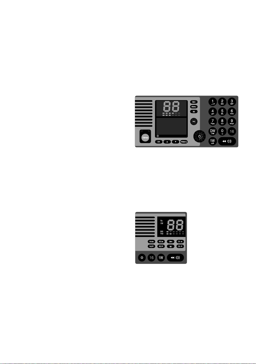
Alarm
Call
DW
1W
SQ
Vol
Int
US
BI
Tx
0191 - 05
CU5000 remote control unit
• The remote unit CU
may be updated with new software.
SB5006 Service tool
• The Service tool itself
can be updated with:
- New software
• The service tool may be configured with:
- New IP address
- Subnet address
- Default gateway address
- Ethernet speed
- IP assignment method
- SPARC II communication settings
- (Logical name settings)
0546
3
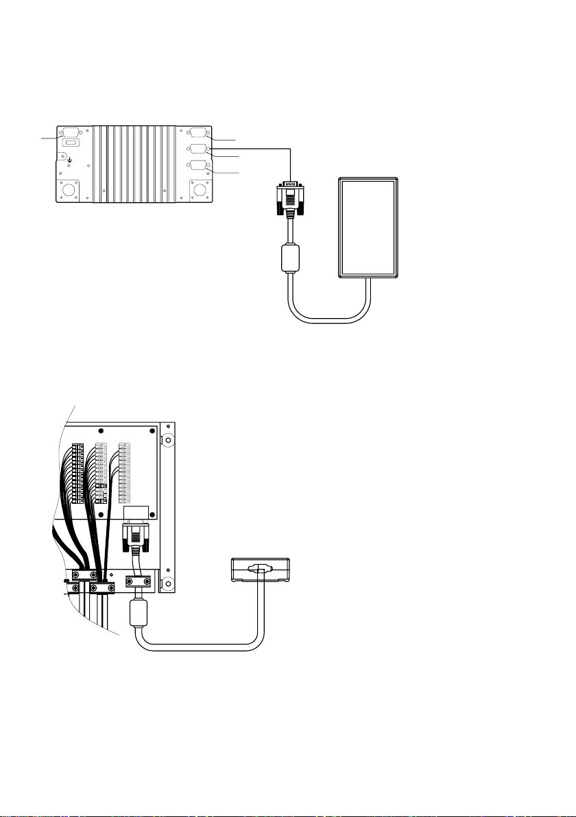
2 Physical Connection
The SB5006 is physically connected to the VHF equipment via the SPARC II bus. The VHF
radio is powering all components – including the SB5006 - via the SPARC II bus connection,
and must always be powered when operating the service tool.
RT5022/RT5020
Power
connector
FUSE
12-24V DC
Main Antenna DSC Antenna
40034A
Figure 2.1: The SB5006 service tool is connected to the VHF 5000 Series radio directly with the
The SB5006 may be connected directly to the SPARC II bus connector at the rear of the
VHF (see Figure 2.1).
SPARC II cable (15 pin Sub-D) delivered with the SB5006 service tool.
IF CU IS CONNECTED TO
EB/CU TERMINALS THEN
X5 X6
EXT /
1
CU LS
2
3
4
5
6
7
8
9
10
11
12
13
14
15
CONNECTIONS
EB/CU
REMOVE J1 & J2 FOR X4
AND J3 & J4 FOR X5
EXT
+12.5V
DATA+
DATA-
TX AF+
TX AF-
GND
+12.5V
RX AF+
RX AF-
+12.5V
EXT LS2
EXT LS2
GND
Line out+
Line out-
LAN
INTERFACE
X7
X4
EXT /
CU LS
SPARC II BUS
EB/CU
Option
Sparc II Bus
Handset
15-pin
sub D male
15-pin
sub D female
9 pin
sub D female
Sparc-bus
SB5006
SB5006
Sparc-bus
40035
Figure 2.2: The SB5006 service tool is connected to the VHF 5000 series in a fixed installation
using the connection box instead.
Alternatively the SPARC II bus is accessible at connector X7 in the connection box, if
installed (see Figure 2.2).
Note: Before connecting the SB5006 to the VHF system, power down the VHF radio.
4
0546
SB 5006
SPARC II
Ethernet
40253
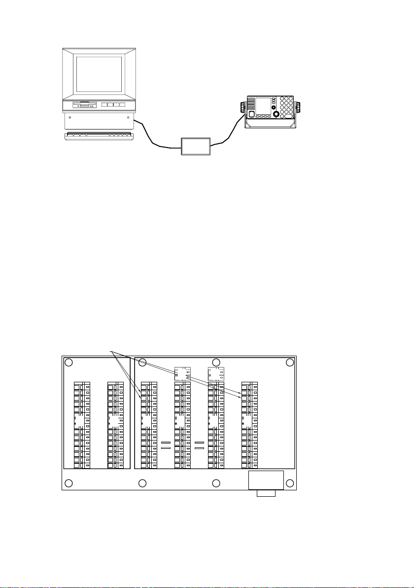
Figure 2.3: A fully connected system with the service tool.
The connection of SB5006 to the service PC is done using the crossed Ethernet cable
(delivered with the SB5006).
2.1 Physical Connection for CU5000 Software
upload
Software upload to a CU5000 in an installation requires data connection to a particular
CU5000 being established exclusively, i.e. the SPARC II bus data lines for all other units on
the bus must be disconnected during this upload process. This includes the VHF itself, the
AP4365/AP1003 Alarm panel, if installed and a second CU5000, if installed (this second
CU5000 may simply be switched off during the upload process). See also fig. 2.4
Note: Remember to restore connection, after the uploads have been made and verify system
operation.
Disconnect
EB/CU
EB/CU
X8
X8
RT50XX
OPTIONS
X1
1
2
3
4
5
X1
6
7
8
9
10
11
12
13
14
15
OPTIONS
OPTIONS
X2
VDR+
VDR-
AUX2
AUX2
AUX1
X2
AUX1
INT LS+
INT LS-
CALL
CALL
GND
NMEA+
NMEA-
ALARM
ALARM
CONNECTIONS
EXT /
RT50XX
CU LS
SPARC II
1
1
2
2
3
3
4
4
5
5
X3
6
6
7
7
8
8
9
9
10
10
J1
11
J2
12
13
13
14
14
15
15
SPARC II BUS
EXT /
CU LS
X4X3
1
2
3
4
5
X4
6
7
8
9
10
J3
J4
13
14
15
CONNECTIONS
40036
Figure 2.4: Inside view of the CB5009 connection box. Lift/disconnect the lines DATA+ and DATA-
(X3 pin 2 and 3) in the terminal connecting any device not being part of the update e.g
the VHF radio and the optional Alarm Panel, as indicated.
IF CU IS CONNECTED TO
EB/CU TERMINALS THEN
X9
X9
REMOVE J1 & J2 FOR X4
AND J3 & J4 FOR X5
1
2
3
4
5
6
7
8
9
10
11
12
13
14
15
X7
LAN
INTERFACE
EXT
X6
+12.5V
DATA+
DATA-
TX AF+
TX AF-
X6
GND
+12.5V
RX AF+
RX AF-
+12.5V
EXT LS+
EXT LS-
GND
Line out+
Line out-
X7
X5
X5
0546
5
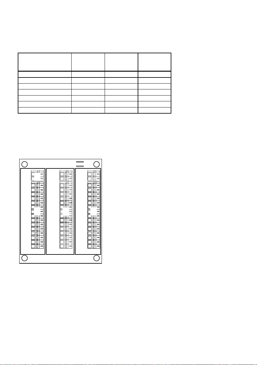
2.2 Alternative Connection
In fixed installations where only an extension box (EB5008) is used a cable may be made up
to provide access to the SPARC II bus through the EB5008 X2 terminals (refer to Tabel 1).
This cable is not part of the SB5006 service toolkit.
VHF SPARC-II
connector 15-pin D-sub
female
Pin1 12.5VDC+ Red/White X2-1
Pin 2 DATA_+ Yellow X2- 2
Pin 3 DATA_- Yellow/ Bla c k X2-3
Pin 6 GND Orange/Red X2-6
Pin 7 12.5VDC+ Orange/ W hite X2-7
Pin 10 12.5VDC+ Black/White X2-10
Pin 13 G ND Black X2-13
Tabel 1: If you do not have access to a 15 pole D-Sub SPARC II connector in the installation, a
cable can be created to get access to the terminals in the extension box. The table
shows only the necessary connections.
SPARC II cable P/N 56.114 may be used for this purpose cutting back wires not used (refer
also to Tabel 1).
Signal
Designation
Cable p/n
56.114
Extension box
terminals
X6:
J1 & J2 MOUNTED = EXT LS
J1 & J2 NOT MOUNTED = CU LS
X4
CU LS+
CU LS-
X1
1
2
3
4
5
X1
6
7
8
9
10
11
12
13
14
15
CU
39817B
X4
X5
EXT LS+
EXT LS-
X2
+12.5V
DATA+
DATA-
TX AF+
TX AF-
GND
+12.5V
RX AF+
RX AF-
+12.5V
EXT LS+
EXT LS-
GND
Line out
Line out
CB/RT50XX
J1
J2
X6
X5
X2
EXT/CU
LS+
EXT/CU
LS-
X3
X6
1
2
3
4
5
X3
6
7
8
9
10
11
12
13
14
15
EB/CU
Figure 2.5: Inside view of EB5008 extension box
6
0546

3 Using the Service Interface
Once the cable connections between the VHF equipment, the SB5006 Service tool and the
PC has been established, call up the HTML browser and type the IP address defined for the
Service tool (factory set default http://169.254.86.86 or lanbox) in the address field. The
Service Interface index page should appear (see Figure 3.1).
Figure 3.1: The index page is the common link for the service tool user interface. The index page
is the menu list in the left area, always available regardless of the page loaded.
The page shown is the front page that will always be displayed when “lanbox” or numeric IP
address is entered in the browser address field, or when the system reboots after a software
upload.
The “VHF Radio” field contains the following information of the VHF 5000 series radio:
• Line 1 – Software Main Release version
• Line 2 – Boot monitor version (only pre-programmable from factory)
• Line 3 – DSP code version (sub-version of the main release)
This information is also available from the menu system in the radio. If the version information does not appear in the “VHF Radio” field after 20 seconds, the connection may have
been lost. Please refer to Appendix – Troubleshooting.
0725
7
The “Service Tool” field contains the following information of the SB5006:
• Line 1 – Current logical name
• Line 2 – Current IP address
• Line 3 and 4 – Software version
The service tool user interface is created as a collection of individual HTML pages managed
by a HTTP server in the SB5006 service tool. The HTML pages that form the service tool
user interface are distributed between the SB5006 service tool memory and the VHF radio
memory.
The pages residing in the service tool are general pages. These pages can always be
reached even if the data connection to the VHF radio is lost.
Pages that are used for direct configuring of the VHF are physically placed in the VHF
memory. This is to ensure the pages always match the current version of the radio software.
No other components in the system (e.g. CUs) hold HTML service pages.
Selecting a page by clicking one of the available buttons/links on the current page, will
request the page from its physical location, request any parameter values that correspond to
the page, and display the page in the browser.
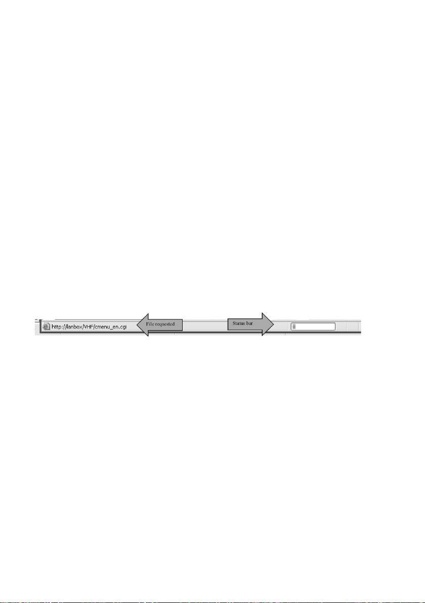
The physical communication interface between the SB5006 and the VHF radio is 9600 Baud
(some pages may take a while to load). While the page and values are fetched from the radio
the activity is indicated in the bottom of the browser window.
Note: It is recommended to wait for the currently requested page to appear, before another
page is request.
Figure 3.2: Activity indicators
8
0546
4 Use Scenarios
This section describes the users interactions required to configure the VHF 5000 series
system.
4.1 Configuration Level
The SB5006 service tool is only required for dealers/service workshops that are required to
do service and/or configuration of VHF 5000 series systems. The service tool is not compatible with other Sailor VHF products (such as VHF2000, VHF3000 and VHF4000 series).
4.1.1 Setting DSC Parameters
Selecting the DSC Parameters menu item on the left side of the index page will bring up the
following page:
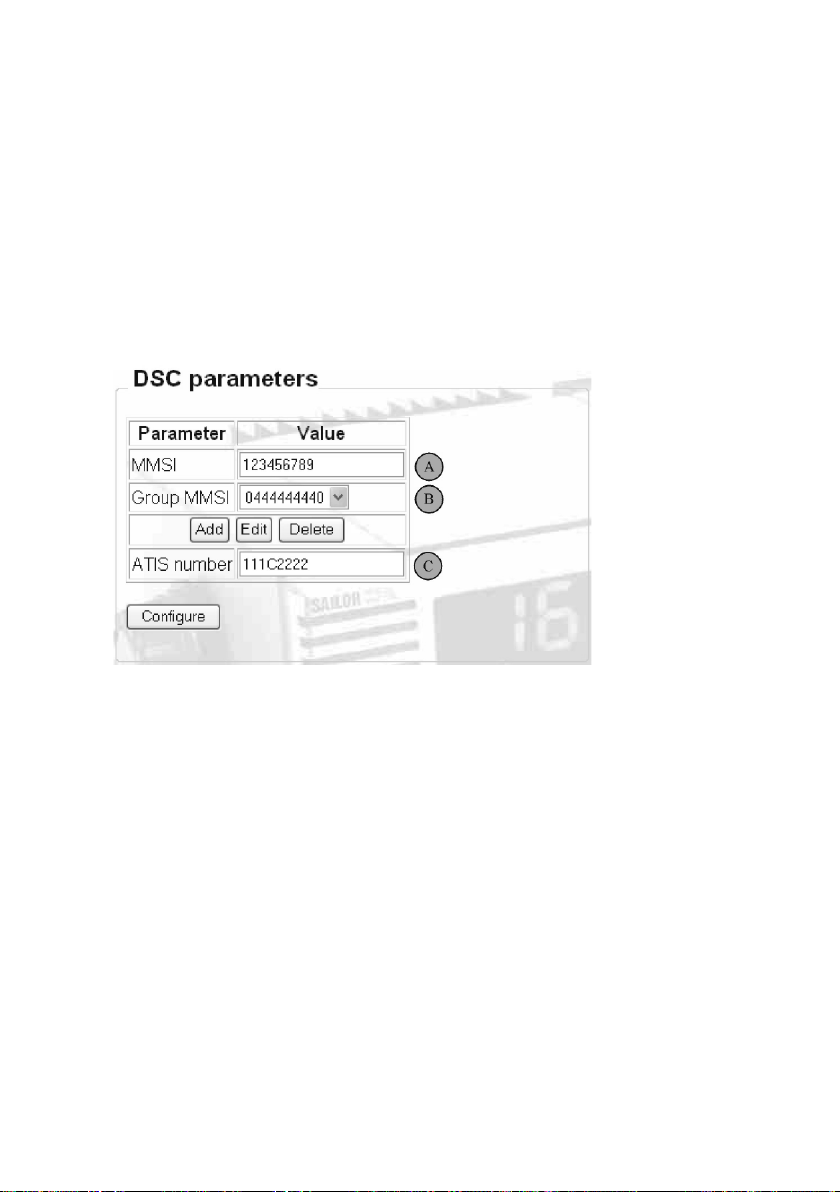
Figure 4.1: DSC relevant parameters.
A - The MMSI number can be changed any time just by entering a new number in the MMSI
field. The following values are valid for MMSI number entry:
• Enter the 9-digit MMSI number.
• Enter a 10-digit MMSI number, where the 10
used to distinguish between multiple radios on the same vessel (range: 0-9).
• Clear the MMSI by removing all digits. Allows the user to program a new MMSI
number one time only from the radio front.
B - Up to 10 MMSI group numbers can be programmed (added, edited or deleted) from the
Group MMSI section. The radio will respond to group calls addressed to one of these
numbers.
C - For radios configured to inland waters (BI) operation, an ATIS code must be applied. The
ATIS number is entered or cleared by simply typing or deleting it from the ATIS number field.
0546
th
digit is a sub-address digit that can be
9
Example: A Dutch (MID-number 244) ship with call sign SP1234, should be programmed
with the following number (letter digit must be capital):
244P1234
4.1.2 Software upload
If new software releases are made available from Thrane & Thrane for the VHF 5000 series
system, such a software file will be made available for download from the Thrane & Thrane
extranet.
To perform the software update the downloaded software file must be stored on the PC
connected to SB5006.
Click the Update software menu item in the left area of the index page.
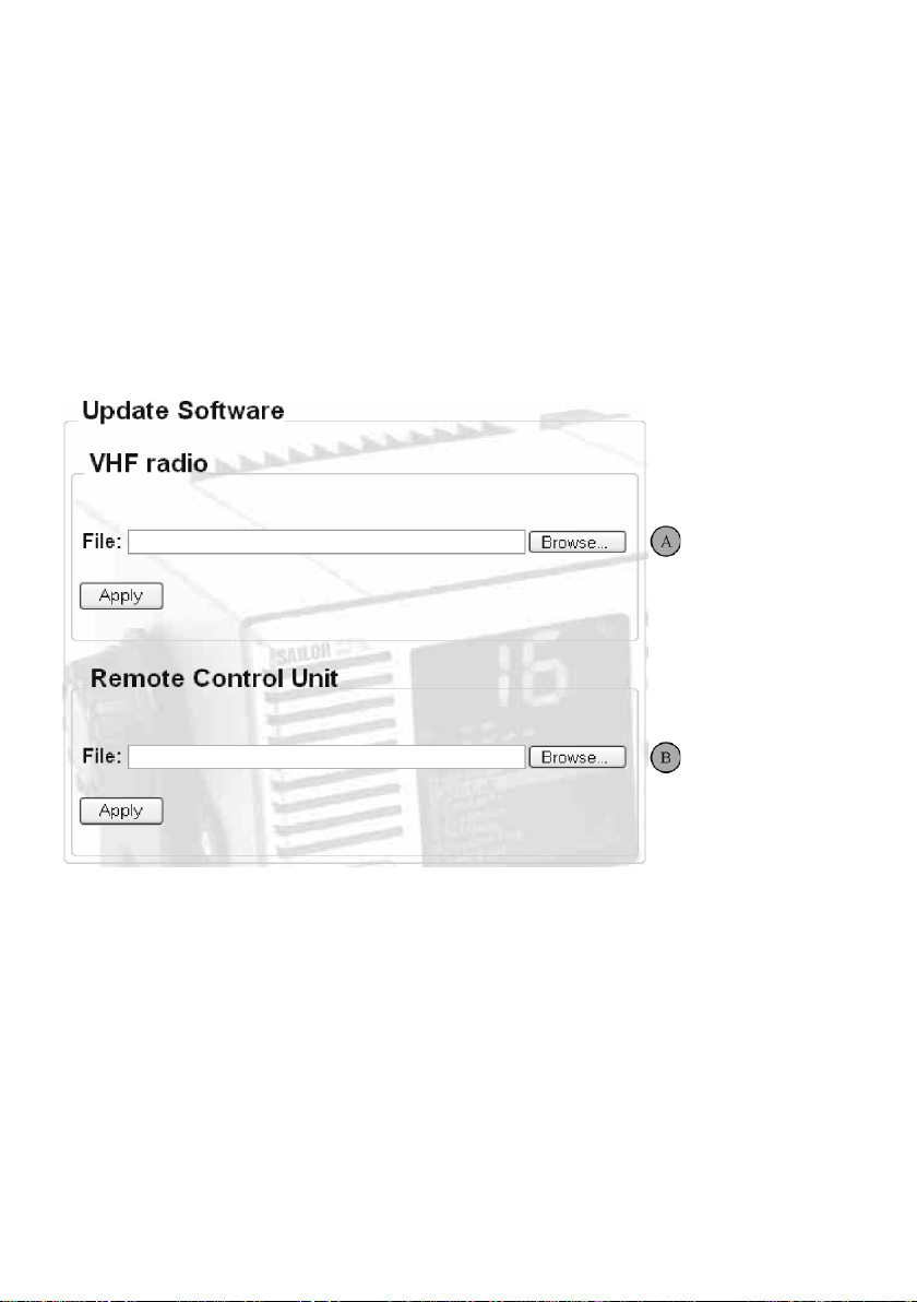
Figure 4.2: The Update Software page is physically located in the SB5006.
A – The VHF software file is simply programmed by clicking the browse button, select the
acquired file and click on Apply.
Note: Any CU5000 in the system must be turned off during VHF software upload.
During the software upload sequence the VHF radio will indicate the software upload
progression by a pattern in the VHF channel display (Figure 4.3).
10
0546
 Loading...