

Thrane&Thrane SAILOR TT-3000E mini-C GMDSS System Installation Manual

TT-3000E mini-C GMDSS System Installation Manual
SAILOR®
by Thrane & Thrane
TT-3000E mini-C GMDSS System
Installation Manual
Copyright© Thrane & Thrane A/S
ALL RIGHTS RESERVED
2006, Thrane & Thrane A/S
Information in this document is subject to change without
notice and does not represent a commitment on the part of
Thrane & Thrane A/S.
Document number: 98-122414 Revision: B
Release Date: 18
th
of July 2007
1/97

TT-3000E mini-C GMDSS System Installation Manual
This page is intentionally left blank
2/97

TT-3000E mini-C GMDSS System Installation Manual
SAFETY SUMMARY
The following general safety precautions must be observed
during all phases of operation, service and repair of this
equipment. Failure to comply with these precautions or with
specific warnings elsewhere in this manual violates safety
standards of design, manufacture and intended use of the
equipment.
Thrane & Thrane A/S assumes no liability for the customer’s
failure to comply with these requirements.
MICROWAVE RADIATION HAZARDS
During transmission this unit radiates microwaves f
rom the
antenna. This radiation may be hazardous if exposed directly
to humans close to the antenna. Make sure that nobody is
closer than the recommended minimum safety distance of 1 ft.
(0.3 meters) during use of the transceiver.
KEEP AWAY F
ROM LIVE CIRCUITS
Operating personnel must not remove equipment covers.
Only qualified maintenance personal must make component
replacement and internal adjustment. Under certain
conditions, dangerous voltages may exist even with the cable
removed. To avoid injuries, always disconnect power and
discharge circuits before touching them.
3/97

TT-3000E mini-C GMDSS System Installation Manual
This page is intentionally left blank
4/97

TT-3000E mini-C GMDSS System Installation Manual
List of Contents:
1 Introduction ...................................... 11
1.1 Initial Inspection.....................................................11
1.2 Storage...................................................................11
1.3 Repacking for shipment..........................................12
1.4 Additional manuals.................................................12
1.5 Abbreviations.........................................................13
2 System Description............................. 14
2.1 TT-3026C mini-C Transceiver.................................15
2.2 TT-3616C Interconnection Box................................16
2.3 AP5042 Inmarsat-C Alarm Panel.............................16
2.4 TT-3042C Remote Alarm/Distress Box....................17
2.5 AP5065 Alarm Panel ...............................................19
2.6 TT-3606E Message Terminal...................................21
2.7 TT-3608A Hard Copy Printer...................................22
2.8 N163S Power Supply...............................................23
2.9 TT-3606E Opt. 003 NMEA Adapter.......................... 24
2.10 Accessories.........................................................25
3 Registration ...................................... 26
4 System Installation............................. 29
4.1 Power requirements..............................................30
4.1.1 Fuses ...............................................................30
4.2 Compass Safe Distance...........................................32
4.3 TT-3026C mini-C Transceiver Installation...............33
4.3.1 Mounting options.............................................33
4.3.1.1 Drilled holes on a flat surface....................33
4.3.1.2 Pole mount 1” ...........................................33
4.3.1.3 Adjustable Pole/Railing Mount..................34
4.3.2 Antenna Mounting Conditions..........................35
4.3.3 Safety Distance for Antenna Units.....................37
4.3.4 Wiring the TT-3026C Mini-C Transceiver.........37
4.3.5 Grounding.......................................................37
4.3.6 Power Connection ...........................................37
4.3.7 Power Requirements........................................38
4.3.8 General Purpose I/O Ports...............................38
4.4 TT-3616C GMDSS Interconnection Box...................40
4.4.1 Mounting of TT-3616C......................................41
5/97

TT-3000E mini-C GMDSS System Installation Manual
4.4.2
Handling of wire terminals in TT-3616C........... 44
4.4.3 Connecting power to TT-3616C....................... 44
4.4.4 Connecting TT-3026C to TT-3616C.................. 46
4.4.5 Connecting TT-3606E to TT-3616C.................. 50
4.4.6 Connecting TT-3042C to TT-3616C.................. 51
4.4.7 Connecting AP50xx to TT-3616C..................... 52
4.4.7.1 T-Port wiring ............................................ 53
4.4.7.2 Direct wiring ............................................ 54
4.4.7.3 Direct wiring - AP5042 powered from TT3616C 55
4.5 TT-3606E Message Terminal.................................. 57
4.5.1 Connectors...................................................... 57
4.5.1.1 Power connector ...................................... 58
4.5.1.2 Communication port................................. 59
4.5.1.3 Printer port............................................... 59
4.5.2 TT-3601E keyboard......................................... 59
4.5.3 Mounting......................................................... 60
4.6 TT-3608A Hard Copy Printer.................................. 62
4.6.1 Mounting plate................................................ 63
4.6.2 Roll Paper Stand.............................................. 63
4.6.3 Mounting......................................................... 64
4.7 AP5042 Inmarsat-C Alarm Panel............................. 65
4.7.1 Mounting......................................................... 65
4.7.1.1 Bracket Mount .......................................... 66
4.7.1.2 Flush mount.............................................. 68
4.7.2 Grounding....................................................... 70
4.7.3 Connecting AP5042......................................... 70
4.7.3.1 AP5042 Power Connection........................ 71
4.7.3.2 AP5042 Network Address Configuration... 72
4.7.3.3 AP5042 Service Interface.......................... 72
4.7.4 AP5042 Initial check and configuration............ 73
4.8 TT-3042C Remote Alarm/Distress Box.................... 75
4.8.1 Mounting......................................................... 76
4.8.2 Cable Connection........................................... 77
5 Test of the system ...............................78
5.1 Basic system verification........................................ 78
5.1.1 DC in LED........................................................ 78
5.1.2 3026 on LED .................................................... 79
5.1.3 3616C OK LED................................................. 79
6/97

TT-3000E mini-C GMDSS System Installation Manual
5.1.4
3026 OK LED....................................................79
5.1.5 SSAS OK LED ...................................................80
5.1.6 GMDSS OK LED ...............................................80
5.2 Distress Button Test ................................................81
5.2.1 TT-3042C Remote Alarm/Distress Box.............81
5.2.2 TT-3042CP Remote Alarm/Distress Box...........82
5.2.3 AP5042 Inmarsat-C Alarm Panel ......................82
5.3 Link test..................................................................83
5.4 Test of backup supply.............................................83
6 Maintenance guidelines...................... 85
6.1 Handling Precautions .............................................85
7 Appendix A........................................ 86
7.1 Mounting stencil.....................................................86
8 Appendix B........................................ 87
8.1 TT-3026C Cable Information...................................87
9 Appendix C ....................................... 88
9.1 TT-3026C Specifications .........................................89
9.2 TT-3606E Specifications..........................................91
9.3 TT-3042C Specifications .........................................92
9.4 TT-3616C Specifications .........................................93
9.5 AP5042 Specifications.............................................94
10 Appendix D ....................................... 95
7/97

TT-3000E mini-C GMDSS System Installation Manual
List of Figures:
Figure 1 TT-3000E mini-C GMDSS System overview............ 14
Figure 3 TT-3616C GMDSS Interconnection Box.................. 16
Figure 4 AP5042 Inmarsat-C Alarm Panel............................. 17
Figure 5 TT-3042C Remote Alarm/Distress Box ................... 18
Figure 6 AP4365 Alarm Panel............................................... 19
Figure 7 TT-3606E Message Terminal.................................. 21
Figure 8 TT-3608A Hard Copy Printer.................................. 22
Figure 9 N163S Power Supply.............................................. 23
Figure 10 Page 1 of the Service Activation Registration Form27
Figure 11 1" Pole mounting.................................................. 34
Figure 12 Vertical and Horizontal adjustable pole mount..... 34
Figure 13 Viewing Angle to the Horizon............................... 36
Figure 14 Mounting near pole or funnel (overhead view) .... 36
Figure 15 Outside view of TT-3616C.................................... 40
Figure 16 Inside view of TT-3616C....................................... 40
Figure 17 Recommended free space around TT-3616C........ 41
Figure 18 Drill template. All measures in mm...................... 42
Figure 19 Grounding using 4mm2 wire. ............................... 43
Figure 21 Power cable connections..................................... 45
Figure 22 Transceiver cable preparation............................. 46
Figure 23 Preparation for grounding of the cable screen..... 47
Figure 24 Fixation of the transceiver cable in TT-3616C....... 48
Figure 25 Mounting of transceiver cable wires.................... 49
Figure 26 RS232 cable connection. ...................................... 50
Figure 28 Preparation of cable for alarm panels .................. 51
Figure 29 Mounting of cables for alarm panels .................... 52
Figure 30 Location of connector J302 ................................... 53
Figure 31 Alarm panels on RS485 bus – T-Port wiring. ......... 53
Figure 32 Alarm panels on RS485 bus – direct wiring........... 54
Figure 33 Powering AP5042 directly from TT-3616C............ 55
Figure 35 TT-3606E Message Terminal................................ 57
Figure 36 TT-3606E Rear Connectors................................... 58
Figure 37 Mounting holes for TT-3606E................................ 60
Figure 38 TT-3606E Mounting Bracket................................. 61
Figure 39 TT-3608A Hard copy printer................................. 62
Figure 40 TT-3608A Paper Roll Stand................................... 63
Figure 41 Mounting holes for TT-3608A (Unit is mm)............ 64
Figure 42 AP5042 Inmarsat-C Alarm Panel........................... 65
8/97

TT-3000E mini-C GMDSS System Installation Manual
Figure 43 Outline & dimensions - bracket mount..................66
Figure 44 Drilling template - bracket...................................67
Figure 45 Outline and dimensions - flush mount...................68
Figure 46 Drilling template - flush mount.............................69
Figure 47 Flush mount assembly..........................................69
Figure 48 RS232 Adapter Cable for Service Interface...........73
Figure 49 System detected, unit ready.................................74
Figure 50 TT-3042C Remote Alarm/Distress Box..................75
Figure 51 TT-3042C Mounting stencil...................................76
Figure 52 TT-3042C connector label ....................................77
Figure 53 TT-3616C LED's and fuses locations......................78
Figure 54 Mounting stencil...................................................86
Figure 55 DeviceNet cable cross section - Thick ..................96
Figure 56 Rockwell DeviceNet T-Connector.........................96
Figure 57 Field installable DeviceNet connector..................97
9/97

TT-3000E mini-C GMDSS System Installation Manual
List of Tables:
Table 1 Accessories............................................................. 25
Table 2 Answers to selected questions in SARF.................... 28
Table 3 System component power requirements................. 30
Table 4 TT-3000E mini-C GMDSS System Fuses................... 31
Table 5 Compass Safe Distance........................................... 32
Table 6 Antenna Safe Distance............................................. 35
Table 7 Radiated intensity.................................................... 37
Table 8 Typical cable resistance.......................................... 44
Table 9 Actual wire colour codes......................................... 52
Table 10 TT-3606E Power Connector................................... 58
Table 11 TT-3606E Std. power cable coding........................ 58
Table 12 Pinout of "Inm-C" connector on AP5042................. 70
Table 13 Pinout of "Power" connector on AP5042................. 71
Table 14 Node ID adressing................................................. 72
Table 15 TT-3026C cable pin assignment............................. 87
Table 16 TT-3026C Technical Spectifications....................... 90
Table 17 TT-3606E Message Terminal Specifications........... 91
Table 18 TT-3042C Technical Specifications........................ 92
Table 19 TT-3616C Technical Specifications........................ 93
Table 20 AP5042 Technical Specifications............................ 94
Table 21DeviceNet color code definition for TT-3000E. ....... 95
Table 22 DeviceNet cable size definition. ............................ 95
10/97

TT-3000E mini-C GMDSS System Installation Manual
WARNING
1 INTRODUCTION
This manual provides instructions for installing a TT-3000E
mini-C GMDSS System.
1.1 I
NITIAL INSPECTION
Inspect the shipping carton immediately upon receipt for
evidence of damage during the transport. If the shipping
carton is severely damaged or water stained, request the
carrier's agent to be present when opening the carton. Save
the carton packing material for future use.
To avoid hazardous electrical shock, do not perform
electrical tests if there is any sign of shipping damage
to any portion of the outer cover. Read the safety
summary at the front of this manual before installing or
operating the TT-3000E mini-C GMDSS System.
Contents of the shipment should be as listed in the enclosed
packing list. If the contents are incomplete, if there is
mechanical damage or defect, or if the system components do
not work properly, notify your dealer.
After you unpack the system please:
• Inspect it thoroughly for hidden damaged, loose
components or loose fittings.
• Inspect the cable harness for stress, loose or broken
wires, or broken cable ties.
• Examine all the components for loose or missing
hardware.
• Tighten all loose hardware.
1.2 S
TORAGE
The TT-3000E system components may be stored or shipped
in temperatures within the limits -40° C to +80° C. It is
11/97

TT-3000E mini-C GMDSS System Installation Manual
recommended that the system is unpacked immediately on
delivery.
1.3 R
EPACKING FOR SHIPMENT
The shipping carton for the TT-3000E mini-C GMDSS System
has been carefully designed to protect the equipment during
shipment. The carton and its associated packing material
should be used when repackaging for shipment. Attach a tag
indicating the type of service required, return address, model
number and full serial number. Mark the carton FRAGILE to
ensure careful handling.
If the original shipping carton is not available, the following
general instructions should be used for repackaging with
commercially available material.
• Wr ap the equipment in heavy paper or plastic. Attach a
tag indicating the type of service required, return
address, model number and full serial number.
• Use a strong shipping container, e.g., a double-walled
carton made of 160 kg test material.
• Seal the shipping container FRAGILE to ensure careful
handling.
1.4 A
DDITIONAL MANUALS
Ref. T&T number Title
[1] TT 98-122464 TT-3000E mini-C GMDSS System
User Manual
[2] TT 98-116080 TT-3026 Software Interface
Reference Manual.
[3] TT 98-122650 TT-3000E SSAS Installation
Manual.
[4] TT 98-109638 TT-3606E Installation and Service
Manual.
[5] TT 98-124401 TT-3606E Opt. 003 NMEA Adapter
Installation Manual.
12/97

TT-3000E mini-C GMDSS System Installation Manual
1.5 A
BBREVIATIONS
AA Accounting Authority
GMDSS Global Maritime Distress and Safety System
GPS Global Positioning System
HPA High Power Amplifier (radio transmitter)
ISN Inmarsat Serial Number of the mini-C
ISP Inmarsat Service Provider
LED Light Emitting Diode
LES Inmarsat-C Land Earth Station
LESO Inmarsat-C Land Earth Station Operator
LNA Low Noise Amplifier (radio receiver)
MES Mobile Earth Station
NCS Inmarsat-C Network Coordination Station
NMEA National Marine Electronics Association
Opt. Short for option
PSA Point of Service Activation
PVT Performance Verification Test
SARF Service Activation Registration Form
SCADA Supervisory Control And Data Acquisition
SSAS Ship Security Alert System
13/97
TT-3000E mini-C GMDSS System Installation Manual
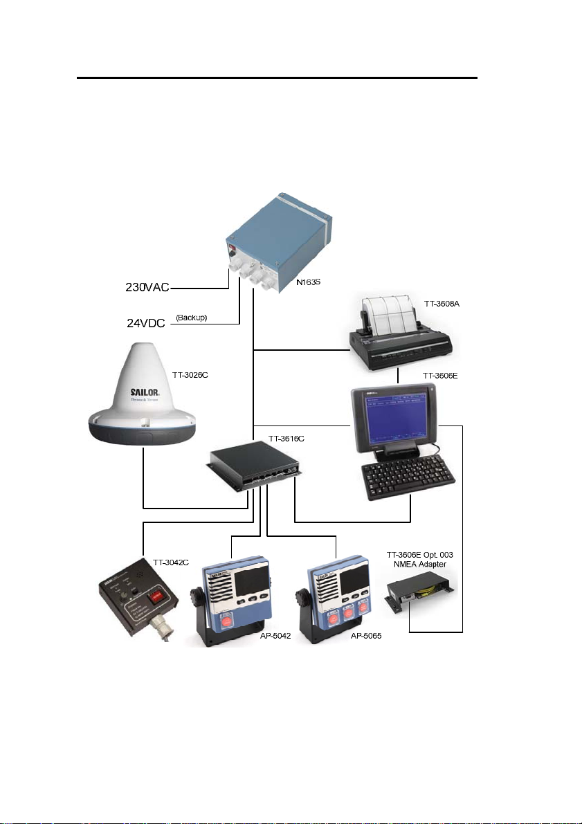
2 SYSTEM DESCRIPTION
An overview of the complete GMDSS system is shown in
Figure 1. The individual products are briefly introduced in
this section. For detailed information about installation please
refer to the following sections.
Figure 1 TT-3000E mini-C GMDSS System overview
A general introduction to the Inmarsat C network is given in
the User Manual [1].
14/97
TT-3000E mini-C GMDSS System Installation Manual
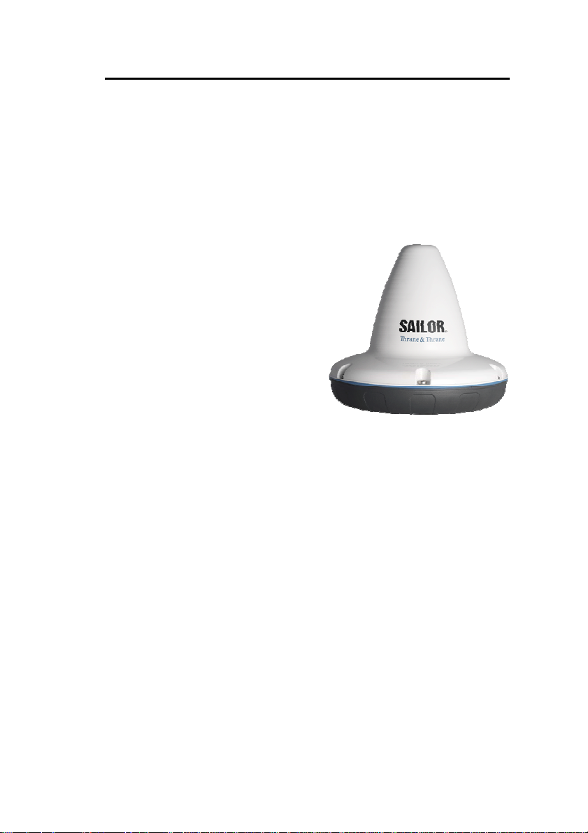
2.1 TT-3026C
MINI-C TRANSCEIVER
The TT-3026C mini-C Transceiver is a complete Inmarsat
mini-C transceiver with built-in LNA/HPA electronics and an
omni-directional antenna designed to operate on vessels. The
housing is sealed and contains no user serviceable parts.
The TT-3026C mini-C
Transceiver is very compact and
is designed to operate in a
corrosive environment and in
extreme weather conditions
without any service.
The TT-3026C mini-C
Transceiver is designed to
operate when the satellite is
visible over the horizon and no
signal path blockage is present.
The TT-3026C mini-C
Figure 2 TT-3026C miniC Transceiver
Transceiver antenna has an
elevation angle of -15° ensuring perfect reception in sea area
A3 (Inmarsat) even when the vessel has pitch and roll
movements due to rough weather.
The TT-3026C mini-C Transceiver has a built-in GPS module,
capable of tracking up to 12 GPS satellites.
15/97
TT-3000E mini-C GMDSS System Installation Manual
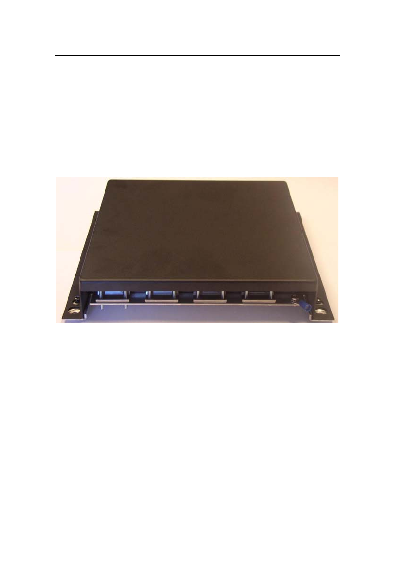
2.2 TT-3616C
INTERCONNECTION BOX
The TT-3616C GMDSS Interconnection Box is designed to
facilitate a simple and robust interconnection of the various
system components. It is designed to be mounted anywhere
inside a vessel and to be located up to 50 meters away from
the TT-3026C mini-C Transceiver and up to 20 meters away
from the TT-3606E Message Terminal.
Figure 3 TT-3616C GMDSS Interconnection Box
2.3 AP5042
INMARSAT-C ALARM PANEL
A mandatory part of a TT-3000E mini-C GMDSS System is the
installation of a distress alarm panel. The AP5042 Inmarsat-C
Alarm Panel is intended specifically for this purpose.
AP5042 can be used as a supplement or replacement for TT3042C Remote Alarm/Distress Box.
The design line of AP5042 matches the design line of the 5000
series radios from Thrane & Thrane.
16/97

TT-3000E mini-C GMDSS System Installation Manual
Figure 4 AP5042 Inmarsat-C Alarm Panel
Up to four AP5042 Inmarsat-C Alarm Pan els can be connected
to a TT-3000E mini-C GMDSS System.
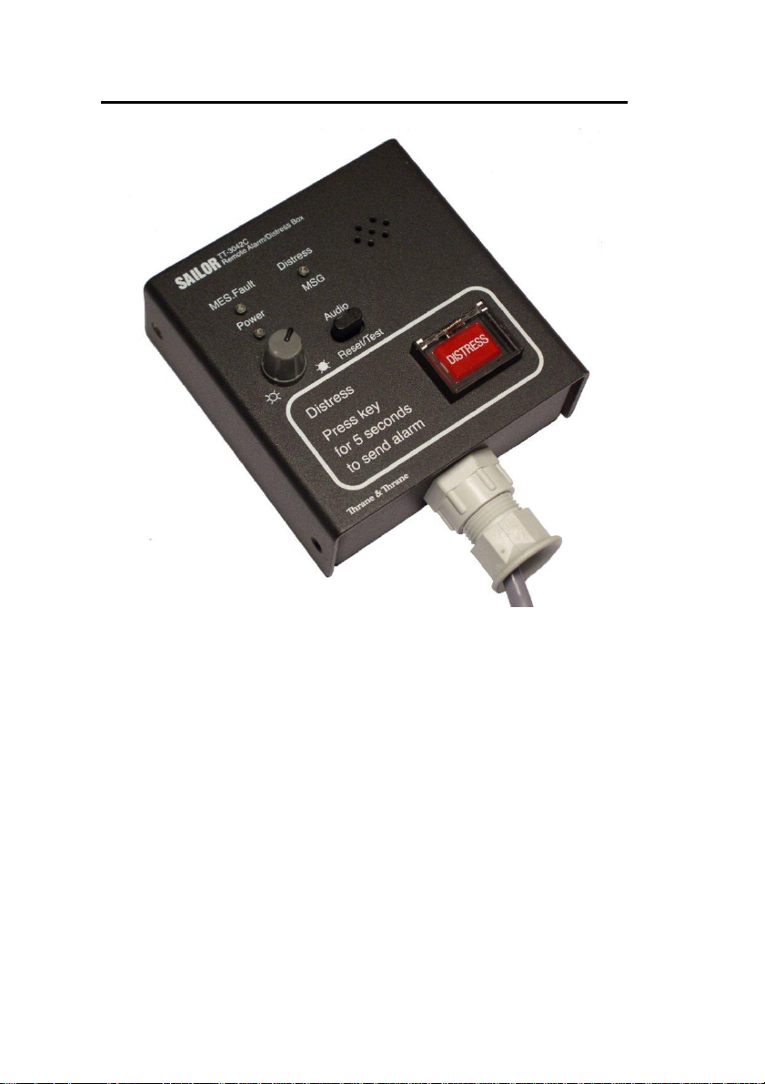
2.4 TT-3042C
REMOTE ALARM/DISTRESS BOX
A mandatory part of a TT-3000E mini-C GMDSS System is the
installation of a distress alarm panel. The TT-3042C Remote
Alarm/Distress Box is designed specifically for this purpose.
17/97
TT-3000E mini-C GMDSS System Installation Manual
Figure 5 TT-3042C Remote Alarm/Distress Box
Up to three TT-3042C Remote Alarm/Distress Boxes can be
connected to a TT-3000E GMDSS System.
The TT-3042C comes in a special modular version for bridge
systems. It has the exact same functionality, but a different
mechanical design.
18/97
TT-3000E mini-C GMDSS System Installation Manual
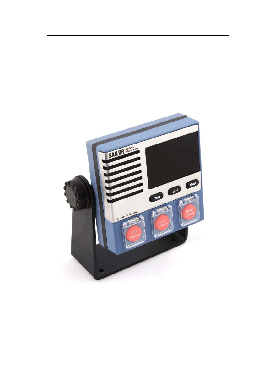
2.5 AP5065
ALARM PANEL
The AP5065 Alarm Panel can be used where a common
interface towards different Thrane & Thrane GMDSS
installations is needed. It can interface towards two InmarsatC GMDSS Systems, two VHF GMDSS Systems and one MF/HF
GMDSS system.
Figure 6 AP4365 Alarm Panel.
AP5065 Alarm Panel is designed to be installed at the cunning
position. For ships with more than one position from where
19/97

TT-3000E mini-C GMDSS System Installation Manual
the ship is normally navigated, it’s possible to interconnect up
to three AP5065 Alarm Panels.
The AP5065 Alarm Panel has an interface towards 3
rd
party
monitoring systems. The relevant alarm statuses for all
attached GMDSS systems are constantly transmitted on a
RS422 line. On another RS422 line it is possible for 3
rd
party
equipment to issue a mute command in order to silence all
GMDSS systems.
For installation of AP5065, please refer to the installation
manual delivered with the unit.
20/97
TT-3000E mini-C GMDSS System Installation Manual
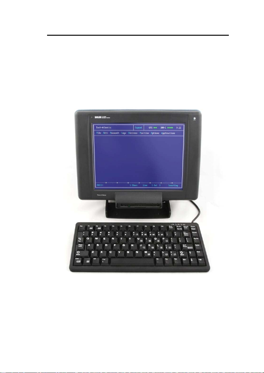
2.6 TT-3606E
MESSAGE TERMINAL
The TT-3606E is a GMDSS approved Message Terminal for the
TT-3000E mini-C GMDSS System. It provides means to send
and receive messages, monitor system status, change the
configuration and test the system.
Figure 7 TT-3606E Message Terminal
21/97

TT-3000E mini-C GMDSS System Installation Manual
2.7 TT-3608A
Figure 8 TT-3608A Hard Copy Printer
HARD COPY PRINTER
The physical installation of the printer is covered by this
manual, section 4.6.
Usage and maintenance of the printer is covered by the
manual provided with the printer.
22/97
TT-3000E mini-C GMDSS System Installation Manual
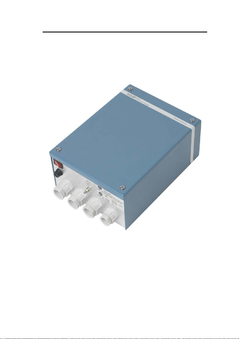
2.8 N163S
POWER SUPPLY
The N163S is an AC/DC power supply designed to
automatically switch from mains to battery supply in case of
mains dropout.
Figure 9 N163S Power Supply
Use of the N163S is optional, but it is a requirement of IMO
that the GMDSS installation is made such that it is operational
both from the ships main source of energy and from an
alternative source of energy.
Please refer to the installation manual delivered with N163S
for further installation information.
23/97
TT-3000E mini-C GMDSS System Installation Manual
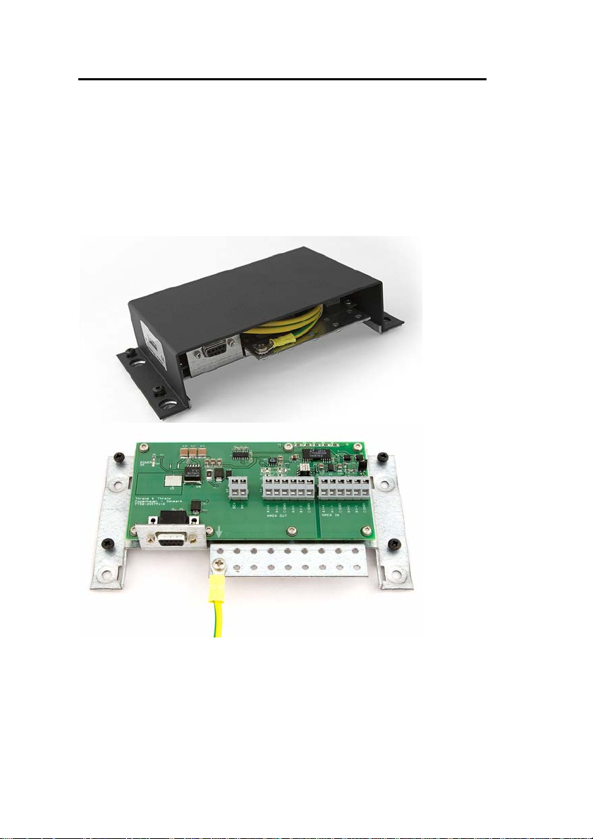
2.9 TT-3606E
OPT. 003 NMEA ADAPTER
In case the position information generated by the build in GPS
receiver in the TT-3026C mini-C Transceiver is needed by
external equipment like VHF radios etc., the TT-3606E Opt.
003 NMEA Adapter is needed to translate the information into
proper NMEA signal levels.
Please refer to the installation manual delivered with the TT3606E Opt. 003 NMEA Adapter for further installation
information (TT 98-124401).
24/97
TT-3000E mini-C GMDSS System Installation Manual
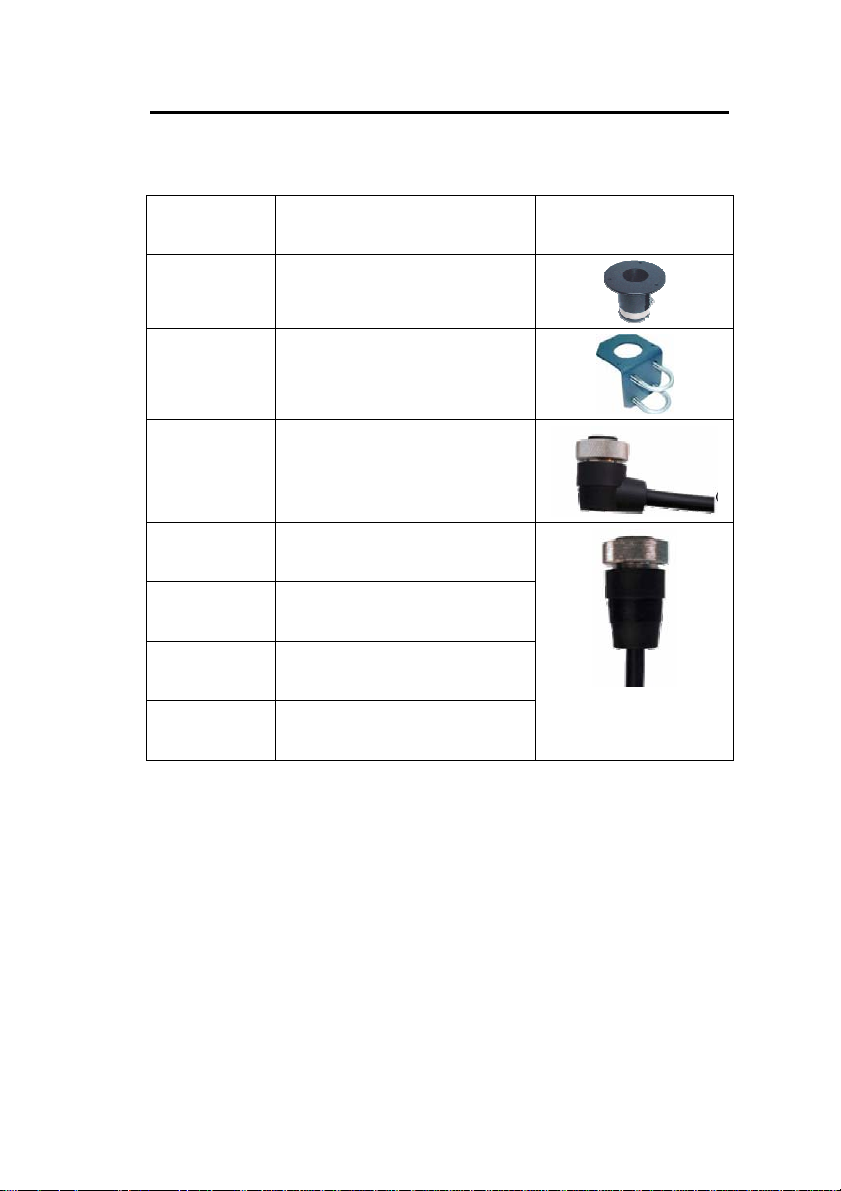
2.10 A
Product
CCESSORIES
Product description Picture
number:
Opt. 101 Standard 1” pole mount kit
Opt. 103 Adjustable pole/railing
mount kit
Opt. 940 Connection cable, 5
meters, with 90° angular
plug
Opt. 941 Connection cable, 5
meters
Opt. 942 Connection cable, 10
meters
Opt. 943 Connection cable, 20
meters
Opt. 946 Connection cable, 50
meters
Table 1 Accessories
25/97

TT-3000E mini-C GMDSS System Installation Manual
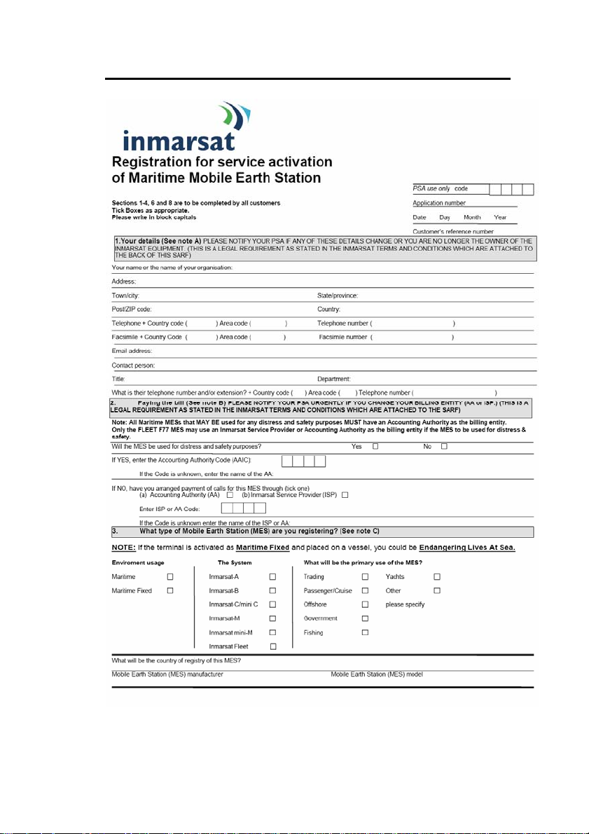
3 REGISTRATION
Before use of the TT-3026C mini-C transceiver on the
Inmarsat-C system it must be registered to the system, which
involves a little paper work. This is done using the SARF
(Service Activation Registration Form) supplied with the miniC MES. Page 1 of the SARF is shown in Figure 6.
The SARF for registration of Maritime MES can also be found
on
www.inmarsat.org (CUSTOMER SUPPORT -> SERVICE
ACTIVATION). The site also contains notes on how to
complete the maritime form.
The Service Activation Registration Form contains different
abbreviations that will be explained here.
The mini-C MES must be registered at either a PSA company
or directly to the ISP. A PSA is a company handling the
activation of Inmarsat mobiles and is short for Point of Service
Activation. ISP is the company that provides the Inmarsat
service and is short for Inmarsat Service Provider. In many
cases the PSA and ISP is the same company that also operates
a Land Earth Station (LES). The local PSA or ISP can be
obtained by following the guidelines in the registration form.
The Service Activation Registration Form also includes
information needed to find out how to pay the bill for the
Inmarsat-C service. This payment will be done directly to the
Accounting Authority. In many cases the Accountin g Auth or it y
(AA) is also the same company as the Inmarsat Service
Provider (ISP).
In addition to the general information like name, address, etc.
the ISN of the mini-C MES must be specified. The ISN is
located on the Delivery Note and in the bottom of the mini-C
MES.
Refer to Table 1 for answers to selected SARF questions.
26/97
TT-3000E mini-C GMDSS System Installation Manual
Figure 10 Page 1 of the Service Activation Registration Form
27/97

TT-3000E mini-C GMDSS System Installation Manual
Question in SARF Answer
Will the MES be used for distress and safety
purposes?
The System?
Mobile Earth Station (MES) manufacturer Thrane & Thrane A/S
Mobile Earth Station (MES) model
Yes
Inmarsat-C/mini C
TT-3026C
Table 2 Answers to selected questions in SARF
When the mini-C MES is registered at the ISP it is ready to be
used on the Inmarsat-C network. The ISP has returned a
Mobile Number for the mini-C MES and prior to operating the
mini-C MES it must be configured with this Mobile Number.
The mobile number can be entered using the TT-3606E
Message Terminal:
1. Choose Options, Configuration, Terminal mode (Alt, O, C,
T) and wait for the blinking cursor to appear. This may
take a while if the transceiver and the Message Handling
program are communicating.
2. Press Enter to see the prompt ' :' on the screen.
3. Type se -u xxxxxxxxx <enter>, where xxxxxxxxx is
the mobile number.
4. Press Esc to leave the Terminal Mode when you're done to
ensure the functionality of your system.
For further information on the terminal interface please refer
to the Software Interface Reference Manual [2].
28/97

TT-3000E mini-C GMDSS System Installation Manual
4 SYSTEM INSTALLATION
This chapter provides specific information enabling you to
install the TT-3000E mini-C GMDSS System with a minimal
effort. The default, or factory configuration, is described
together with procedures for altering this configuration.
The GMDSS system components covered in this section are:
TT-3026C Mini-C Transceiver
TT-3616C GMDSS Interconnection Box
TT-3606E Message Terminal
TT-3601E Keyboard
TT-3608A Hard Copy Printer
TT-3042C Remote Alarm/Distress Box
AP5042 Inmarsat-C Alarm Panel
Please note that installation of N163S Power Supply and
AP5065 Alarm Panel are covered by separate manuals
provided with the units.
IMPORTANT: DO NEVER TEST THIS INSTLLATION BY
SENDING AN ALERT ON-AIR. ALSO BE CAREFUL NOT TO
SEND FALSE ALERTS DURING INSTALLATION. Any distress
alerts coming through the Inmarsat-C network will be taken
seriously by the receiving authorities.
If a false alert is sent by accident – despite all precautions – it
is important to inform the relevant authorities before a rescue
operation is initiated. See the User’s Manual for more
information about this [1].
29/97

TT-3000E mini-C GMDSS System Installation Manual
4.1 P
A TT-3000E mini-C GMDSS System operates on either 115
VAC, 230 VAC or a 24 V floating DC (nominal value)
OWER REQUIREMENTS
1
. The
N163S provides automatic switch over to the DC supply in
case a drop out occurs on the mains.
The total power consumption varies primarily due to system
activities. As a guide-line, please note the power consumption
of the following equipment:
Power requirements Receive
TT-3026C mini-C Transceiver.
Floating DC (10.5-32V).
TT-3616C GMDSS Interconnection Box.
Floating DC (10.5-32V).
TT-3606E Message Terminal, incl. Keyboard.
Floating DC (10.5 - 32V)
TT-3608A Printer 220AC or option 010 DC
supply floating (10.5 - 32V)
AP5042 (8 - 32V) 0.3W 0.8W
AP5065 (21 - 32V) 1W 3W
TT-3042C Remote Alarm/Distress Box 0.2 W
Total: 50W 92W
mode
1.8W Max. 32W
1W 2W
13W
average
33W 33W
standby
Transmit
mode
20W
peak
1W
Table 3 System component power requirements
4.1.1 F
USES
In case you experience that a fuse needs replacement, please
check that the equipment has not been exposed to physical
damage before fuse replacement takes place.
As a guide-line, please note the equipment fuse location given
in Table 4.
1
The system can be operated from a DC supply down to 12V
provided the cable lengths are limited, please refer to section
4.4.3.
30/97
 Loading...