


Thrane & Thrane A/S
SAILOR Fleet77
TT-3084A
&
SAILOR Fleet55
TT-3086A
User Manual
Copyright© Thrane & Thrane A/S
ALL RIGHTS RESERVED

Information in this document is subject to change without
notice and does not represent a commitment on the part of
Thrane & Thrane A/S. It is recommended to download the
latest version of the manual from the Thrane Extra net or
request this from the distributor.
© 2005 Thrane & Thrane A/S. All rights reserved. Printed
in Denmark.
Trademark Acknowledgements:
WinPoET is a trademark of iVasion, a RouterWare Company.
Document no. TT98—116874-F.
Release date: 26 May 2005.
Safety Summary
The following general safety precautions must be observed during all phases
of operation, service and repair of this equipment. Failure to comply with
these precautions or with specific warnings elsewhere in this manual violates
safety standards of design, manufacture and intended use of the equipment.
Thrane & Thrane A/S assume no liability for the customer's failure to co mply
with these requirements.
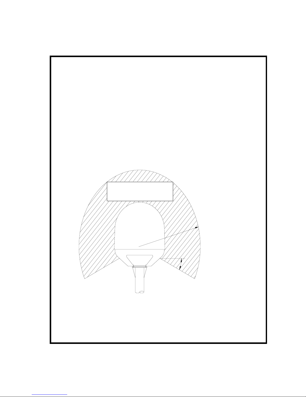
Microwave Radiation Hazards
During transmission the antenna in this system radiates Microwave Power.
This radiation may be hazardous if exposed directly to humans, close to the
antenna. During transmission, make sure that nobody gets closer than the
recommended minimum safety distance. The minimum safety distance to the
antenna on the focal line, is 4m.
4.0m (Fleet77)
2,0m (Fleet55)
25°
MICROWAVE RADIATION
NO PERSONNEL WITHIN 4 m (Fl eet 77)
NO PERSONNEL WITHIN 2 m (Fl eet 55)
GROUND THE EQUIPMENT
To minimize shock hazard, the equipment chassis and cabinet must be
connected to an electrical ground.

DO NOT OPERATE IN AN EXPLOSIVE ATMOSPHERE
Do not operate the equipment in the presence of flammable gases or
fumes. Operation of any electrical equipment in such an environment
constitutes a definite safety hazard.
KEEP AWAY FROM LIVE CIRCUITS
Operating personnel must not remove equipment covers. Component
replacement and internal adjustment must be made by qualified
maintenance personnel. Do not replace components with the power cable
connected. Under certain conditions, dangerous voltages may exist even
with the power cable removed. To avoid injuries, always disconnect power
and discharge circuits before touching them.
DO NOT SERVICE OR ADJUST ALONE
Do not attempt internal service or adjustments unless another person,
capable of rendering first aid resuscitation, is present.

Table of Contents
Table of Contents
1
About the Manual...................................................... 1
2 Introduction ............................................................. 3
2.1 Abbreviations..................................................... 3
2.2 The Inmarsat Fleet Service .................................. 5
2.3 The SAILOR Fleet77 system ................................. 9
2.4 The SAILOR Fleet55 system ............................... 12
2.5 Hardware Interfaces.......................................... 15
2.5.1 Two Cradle/Handset interfaces.................. 16
2.5.2 Three Analogue RJ11 interfaces ................ 16
2.5.3 ISDN interface........................................ 17
2.5.4 RS-232 interface..................................... 19
2.5.5 NMEA 0183/2000 interface....................... 19
2.5.6 Discrete I/O interface .............................. 20
2.5.7 USB Interface......................................... 20
2.5.8 Ethernet Interface................................... 21
2.5.9 Power Connector..................................... 21
2.6 The Handset .................................................... 22
2.6.1 LCD/LED................................................ 23
2.6.2 Function Buttons..................................... 26
2.6.3 Alpha-Numeric Buttons............................ 30
2.7 Distress Cradle................................................. 32
3 Getting started ....................................................... 35
3.1 Get ready to make a call.................................... 35
3.1.1 How to power on the system. ................... 35
3.1.2 How to power down the system. ............... 38
3.2 Use of PIN codes. ............................................. 39
3.3 Normal calls..................................................... 40
3.3.1 Call from handset.................................... 40
3.3.2 Calling the terminal................................. 41
3.4 Distress call..................................................... 42
3.4.1 How to make a Distress call...................... 42
May 2005 i

Table of Contents
3.4.2 Distress call failure...................................43
3.4.3 Distress and Priority call to the ship............43
3.5 MPDS connection...............................................44
3.5.1 Call waiting.............................................45
3.6 ISDN Connection...............................................46
4 Operation................................................................49
4.1 Menu System....................................................49
4.1.1 Phonebook..............................................50
4.1.2 Area.......................................................52
4.1.3 LES........................................................53
4.1.4 Mailbox ..................................................54
4.1.5 Help Desk...............................................55
4.1.6 Alarm Log...............................................56
4.1.7 Status....................................................57
4.2 Call functions.................................................... 59
4.2.1 Call using phone book ..............................59
4.2.2 Call from handset connected to RJ11 ..........60
4.2.3 Call from an ISDN phone ..........................60
4.2.4 Fax call ..................................................61
4.2.5 Priority calls............................................62
4.2.6 Internal calls...........................................63
4.3 Super User functions..........................................64
4.3.1 Call Logs ................................................64
4.3.2 Routing ..................................................66
4.3.3 Data setup..............................................68
4.3.4 Contrast .................................................69
4.3.5 Ring setup ..............................................70
4.3.6 Key Beep................................................70
4.3.7 Set UTC Time..........................................71
4.3.8 Set UTC Date ..........................................71
4.3.9 Disclose Pos............................................72
4.3.10 NMEA.....................................................72
4.3.11 Allowed Dial ............................................73
4.3.12 Ph.Book Dial ...........................................74
4.3.13 Auto Prefix..............................................75
4.3.14 BarServiceIn...........................................75
ii May 2005

Table of Contents
4.3.15 BarServiceOut ........................................ 76
4.3.16 LED Dimm ............................................. 77
4.3.17 Antenna Setup........................................ 77
4.3.18 DistressTest........................................... 79
4.3.19 Alarm log............................................... 80
4.3.20 Warning Log........................................... 81
4.3.21 Help Desk.............................................. 81
4.3.22 PIN codes .............................................. 82
4.3.23 Mailbox.................................................. 83
4.3.24 RJ11 Setup ............................................ 84
4.3.25 LES Configuration ................................... 85
4.3.26 Additional Features ................................. 87
4.3.27 Data Limits ............................................ 88
4.3.28 Call Waiting Notification ........................... 89
5 PC programs .......................................................... 93
5.1 System Set-up using FleetCP.............................. 93
5.1.1 The Map ................................................ 94
5.1.2 Pin Codes .............................................. 95
5.1.3 Phonebook............................................. 96
5.1.4 Satellite Setup........................................ 97
5.1.5 Routing ................................................. 98
5.1.6 Setting up Time and Date......................... 99
5.1.7 Barring Services ....................................100
5.1.8 Settings................................................101
5.1.9 Antenna ...............................................102
5.2 Set-up of data equipment .................................103
5.2.1 Set-up for MPDS over RS-232..................103
5.2.2 Set-up for ISDN.....................................109
5.2.3 Set-up for 64 kbit/s UDI using USB ..........114
5.3 Set-up using Ethernet/PPPoE.............................125
5.3.1 Windows XP with Built-in PPPoE Client ......125
5.3.2 Windows 2000 WinPoET PPPoE Client........127
6 Troubleshooting.....................................................131
6.1 List of Error messages......................................131
6.1.1 Inmarsat defined alarms.........................131
6.1.2 Non Inmarsat Alarms..............................145
May 2005 iii

Table of Contents
7 Index ...................................................................151
Appendix A - Menu Tree.................................................153
iv May 2005

Abbreviations About the Manual
1
1 About the Manual
Congratulations on purchasing your SAILOR Fleet product.
Whether you have chosen a TT-3084A SAILOR Fleet77 or a
TT-3086A SAILOR Fleet55, the system makes it possible for
you to communicate from virtually any ocean region i n the
world using the Inmarsat Fleet service established by
Inmarsat. Both systems supports high-speed data (64
kbit/s circuit switched and packet data) and high quality
voice as well as inexpensive voice services. In addition the
SAILOR Fleet77 optionally supports 128 kbit/s data servi ce.
This manual has the following chapters:
Chapter 2 Introduction - an overview of the Inmarsat
Fleet system and its services.
Chapter 3 Getting started- a description of how to make
and receive calls and the use of PIN codes.
Chapter 4 Operation- a detailed description of the menu
system in the terminal.
Chapter 5 PC programs- a description of how to use the
accompanying configuration PC software (FleetCP) and to
setup the PC for data connections.
Chapter 6 Troubleshooting – a description of the most
common errors, how to deal with them and how to get
further help if necessary.
Chapter 7 Index- a subject index
Appendix A - Menu Tree
May 2005 1


Abbreviations Introduction
2
2 Introduction
2.1 Abbreviations
ACU Antenna Control Unit
ADU Above Deck Unit
AORE Atlantic Ocean Region East
AORW Atlantic Ocean Region West
BDU Below Deck Unit
FEU Front End Unit
GPS Global Positioning System
IMN Inmarsat Mobile Number
ISDN Integrated Services Digital Network
ISN Inmarsat Serial Number
IOR Indian Ocean Region
ISP Inmarsat Service Provider
LCD Liquid Crystal Display
LED Light Emitting Diode
LES Land Earth Stations
MES Mobile Earth Station
MMI Man Machine Interface
MPDS Mobile Packet Data Service
MSN Multiple Subscriber Number
NCS Network Co-ordination Station
NSR Network Status Record
PIN Personal Identification Number
PABX Private Automatic Branch Exchange
PUK Personal Unblocking Key
POR Pacific Ocean Region
PSTN Public Services Telephone Network
RCC Rescue Co-ordination Center
STE Secure Telephone Equipment
STU Secure Telephone Unit
May 2005 3

Introduction Abbreviations
2
T&T Thrane & Thrane A/S
TNID Terrestrial Network ID
UDI Unrestricted Digital Information
USB Universal Serial Bus
4 May 2005

The Inmarsat Fleet Service Introduction
2
2.2 The Inmarsat Fleet Service
The Inmarsat Fleet service is based on 4 Geo-stationary 3rd
generation satellites situated above the equator. Geostationary means that the satellites are always located in
the same position, i.e. they rotate at the same speed as
that of the earth. Each satellite covers a certain area
(footprint) and supports a number of powerful spot-beams
making the service available in virtually all ocean regions
on the earth between approximately 70°N and 70°S.
The 4 Geo-Stationary Inmarsat Satellites
The satellites are your connection to the worldwide
networks, and they are managed by the Network Coordination Stations (NCSs), run by Inmarsat. The primary
functions of the NCSs are to constantly keep track of which
terminals are logged on to the system, and assign a free
channel whenever a call is made.
The gateway between the public network and the satellites
are operated by Land Earth Stations (LES). The LES are run
by different operators around the world.
The Fleet services are prepared for operation with the next
generation of Inmarsat satellites (Inm-IV) expected in
2005.
May 2005 5
Introduction The Inmarsat Fleet Service
2
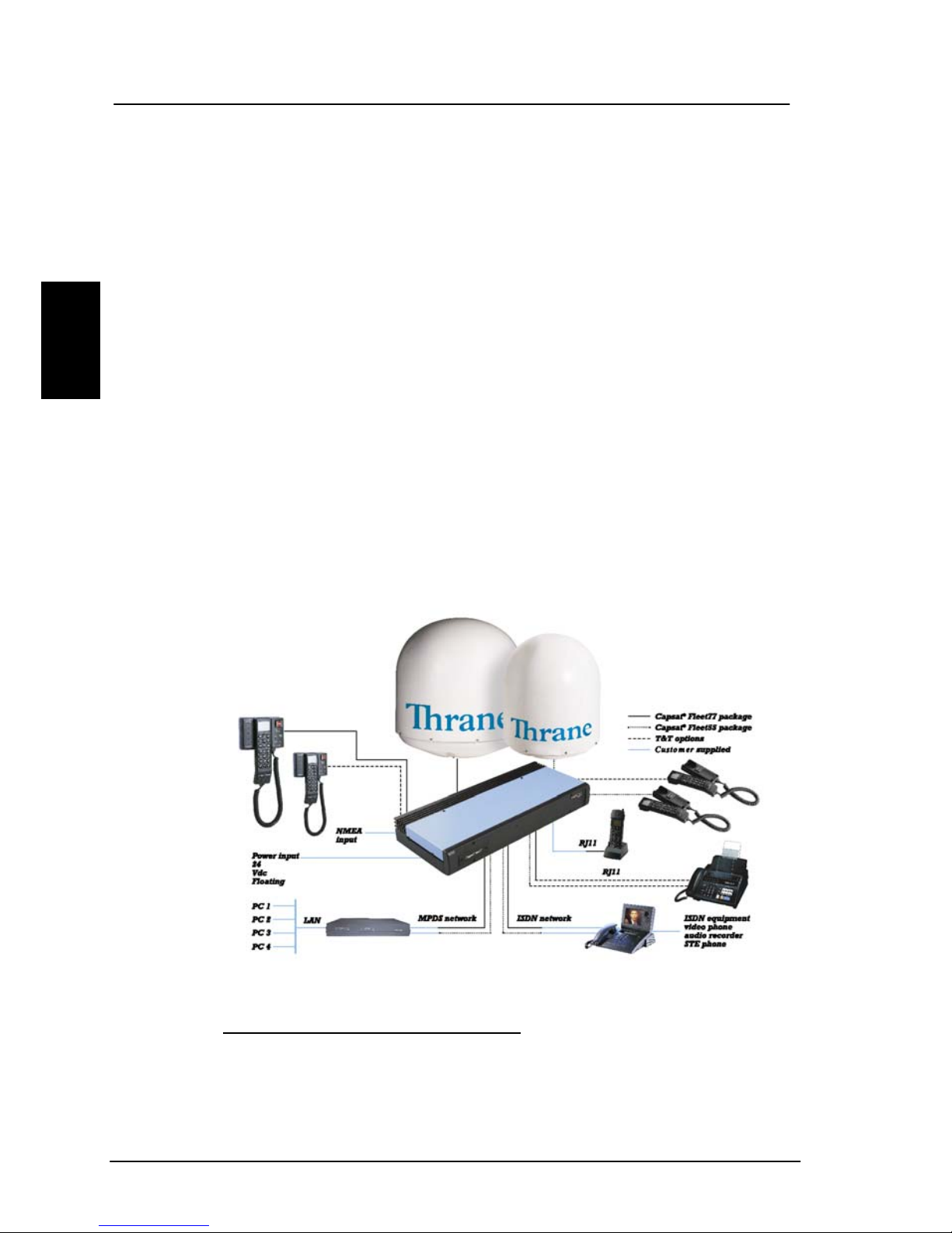
The services supported by the Inmarsat Fleet encompass:
• High speed services
• 2 x 64 / 2 x 56 kbit/s data
1
• 64 kbit/s data
• 56 kbit/s data
• Speech
• 3.1 kHz audio
• MPDS
• Low speed services
• mini-M voice
• 9.6 kbit fax
For a detailed description of each service see the last
section of this chapter. The above-mentioned services
allow for a wide range of applications. Examples are shown
below.
1
128 kbit/s is only available on new F77 systems
6 May 2005

The Inmarsat Fleet Service Introduction
2
Important notice: Before a terminal can be used on the
network, it has to be commissioned by one of the Inmarsat
Service Providers (ISP’s). In order to use the different
Inmarsat Fleet services it is necessary to have at least one
Inmarsat Mobile Number (IMN) for each of the above
mentioned services. In case all 8 services are
commissioned on your terminal, you will have 8 IMN
numbers.
Calling an Inmarsat Fleet terminal corresponds to making
international calls. If the satellite region/area is not known
for the terminal the “country” code for a terminal is 870.
When you dial up to an Inmarsat Fleet terminal through
the public network, you have to dial the IMN number in
addition to the international access code for Inmarsat, e.g.:
+870 600 555 555
Making calls from an Inmarsat Fleet terminal corresponds
to making international calls as the country code always
has to be dialed.
Service explanation:
The low speed services have a lower tariff than the high
speed services, as these are high quality audio or high
speed data services and thus require more bandwidth.
The 128 kbit/s UDI (Unrestricted Digital Information)
service enables 2 x 64 kbit/s or 2 x 56 kbit/s bi-directional
transmission of data to and from terrestrial ISDN networks
The 64 kbit/s UDI (Unrestricted Digital Information)
service enables the bi-directional transmission of data to
and from terrestrial 64 kbit/s ISDN networks. The 56
kbit/s UDI service is similarly used to make a connection
to 56 kbit/s ISDN networks, which are primarily used in
North America.
May 2005 7

Introduction The Inmarsat Fleet Service
2
The Speech and 3.1 kHz audio services make it possibl e
to establish high quality analogue connections with quali ty
equal to terrestrial analogue connections via digital
networks/switches. The Speech service is used for high
quality voice connections, whereas 3.1 kHz audio can be
used to transfer analogue signals between fax machines
and modems with an analogue 2-wire interface. The 3.1
kHz audio service is transparent, and is suitable for all
analogue applications including secure telephones.
The MPDS service is a packet data service where the tariff
depends on the amount of data sent and received. This
service is a more cost-effective solution for web browsing,
and other applications where there is no need for constant
transmission of data in both directions. It is also suitable
for applications where a constant connection is required,
because the user is no longer charged the “per minute
rate”.
The mini-M voice service is only for voice transmission.
The voice transmitted over the satellite is subject to a
compression process that reduces the bandwidth to 4.8
kbit/s and subsequently the cost.
The 9.6 kbit Fax allows you to send and receive faxes
using a standard office fax machine. This service replaces
the previous Mini-M fax service. Using this service is
usually more cost effective compared to the 3.1 kHz audio
service.
8 May 2005
The SAILOR Fleet77 system Introduction
2
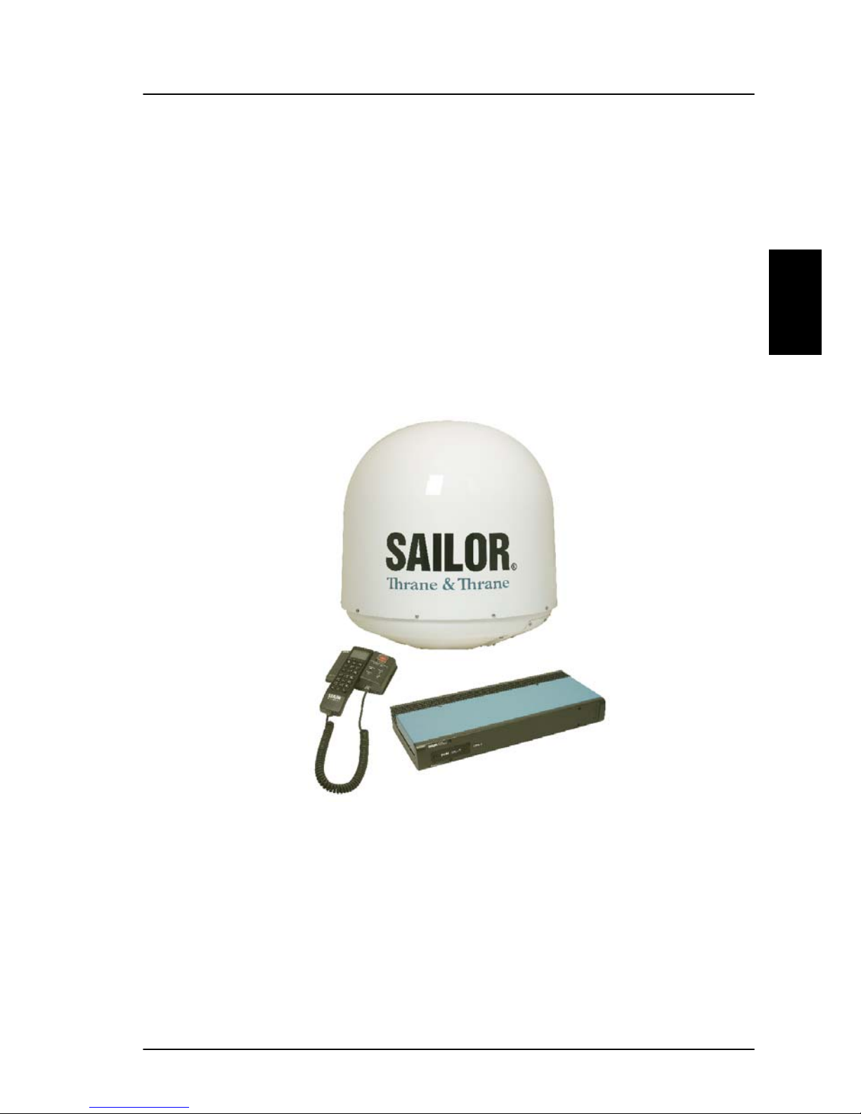
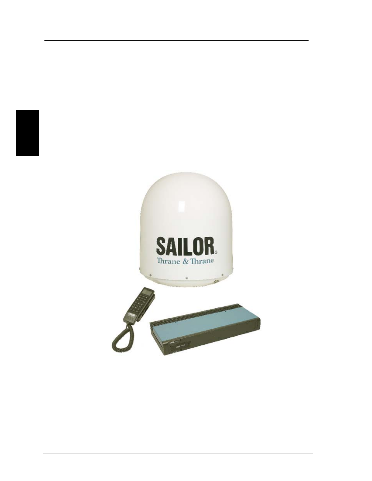
2.3 The SAILOR Fleet77 system
The SAILOR Fleet77 System includes the following system
components:
• TT-3008C SAILOR Fleet77 Antenna (ADU)
• TT-3038C SAILOR Fleet77 Electronics Unit (BDU)
• TT-3622B SAILOR Fleet77 Distress Cradle
• TT-3620F SAILOR Fleet Control Handset (4 wire)
Accessories (manual, software, etc.)
Instructions on how to assemble the system, wiring and
specification, can be found in the Installation Manual.
May 2005 9
Introduction The SAILOR Fleet77 system
2
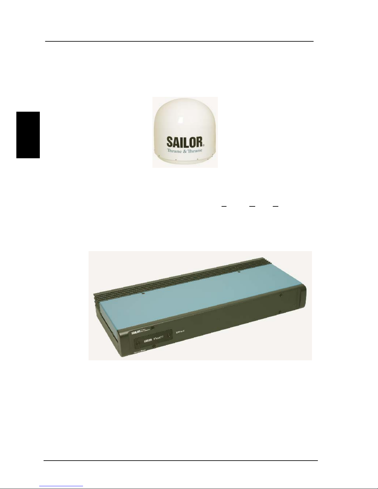
TT-3008C Antenna
The TT-3008C antenna or ADU (
Above Deck Unit) is a
stabilized high-gain antenna. The antenna has built-in all
functions for satellite tracking including a GPS system.
TT-3038C-128 SAILOR Fleet77 Electronics Unit (BDU)
All connectors for external equipment are placed on the
rear of the terminal (BDU). On the front a configuration
module is attached. This module stores all system
10 May 2005

The SAILOR Fleet77 system Introduction
2
configuration data. It contains all necessary data to recover
the system after a replacement of the BDU.
TT-3622B SAILOR Fleet Cradle with Distress and
TT-3620F SAILOR Fleet Control Handset (4 wire)
The Handset is primary used to make telephone calls.
Furthermore it can be used to configure the system. For a
detailed description of the handset see section 2.6.
The Cradle has a distress button, a stop button and three
LED's. The distress button, which is protected by plastic
glass, is used to initiate a distress call. The stop button can
be used to abort a distress call. The three LED's indicates,
power, distress test and priority calls. For a detailed
description of the cradle see section 2.7.
May 2005 11
Introduction The SAILOR Fleet55 system
2
2.4 The SAILOR Fleet55 system
The SAILOR Fleet55 System includes the following system
components:
• TT-3008F SAILOR Fleet55 Antenna (ADU)
• TT-3038C SAILOR Fleet55 Electronics Unit (BDU)
• TT-3622C SAILOR Fleet Cradle without Distress
• TT-3620F SAILOR Fleet Control Handset (4 wire)
Accessories (manual, software, etc.)
Instructions on how to assemble the system, wiring and
specification, can be found in the Installation Manual.
12 May 2005

The SAILOR Fleet55 system Introduction
2
TT-3008F SAILOR Fleet55 Antenna
The TT-3008F antenna or ADU (Above Deck Unit) is a
stabilized high-gain antenna. The antenna has built-in all
functions for satellite tracking including a GPS system.
TT-3038C SAILOR Fleet55/77 Electronics Unit (BDU)
All connectors for external equipment are placed on the
rear of the terminal (BDU). On the front a configuration
May 2005 13
Introduction The SAILOR Fleet55 system
2
module is attached. This module stores all system
configuration data. It contains all necessary data to recover
the system after a replacement of the BDU.
TT-3622C SAILOR Fleet Cradle without Distress
TT-3620F SAILOR Fleet Control Handset (4 wire)
The Handset is primary used to make telephone calls.
Furthermore it can be used to configure the system. For a
detailed description of the handset see section 2.6.
14 May 2005
Hardware Interfaces Introduction
2
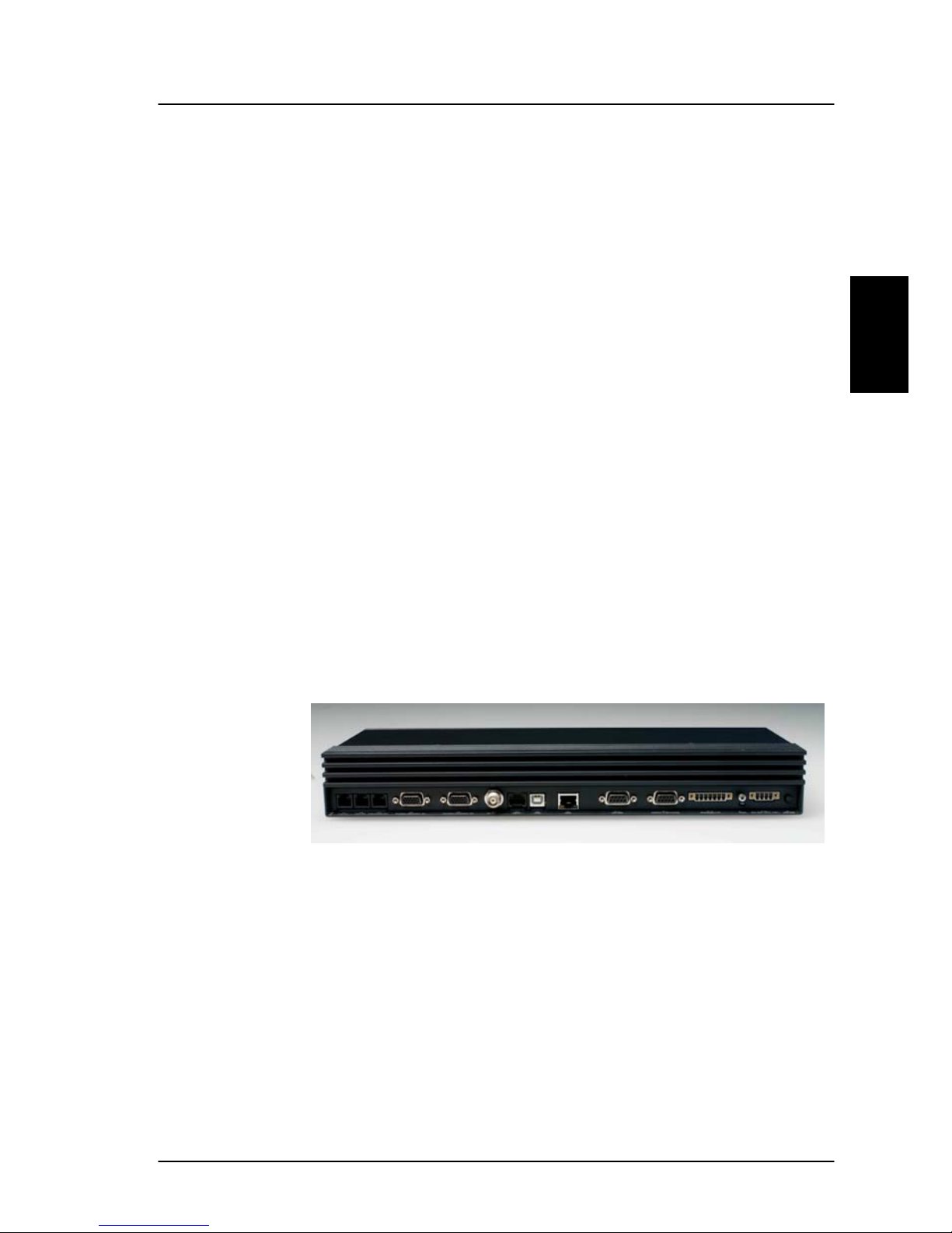
2.5 Hardware Interfaces
The Electronic Units of the SAILOR Fleet77 and the SAILOR
Fleet55 has the following hardware interfaces:
• Analogue RJ11 number 1 (X1)
• Analogue RJ11 number 2 (X2)
• Analogue RJ11 number 3 (X3)
• Handset 1 (X4)
• Handset 2 (X5) (For future use)
• ISDN ( Integrated Services Digital Network) (X7)
• USB (Universal Serial Bus) (X8)
• Ethernet (X9)
• Serial connector 1 (X10)
• NMEA 0183/2000 (X11) (For future use)
• 4 Discrete I/O (X12) (For future use)
• Power Connector (X13)
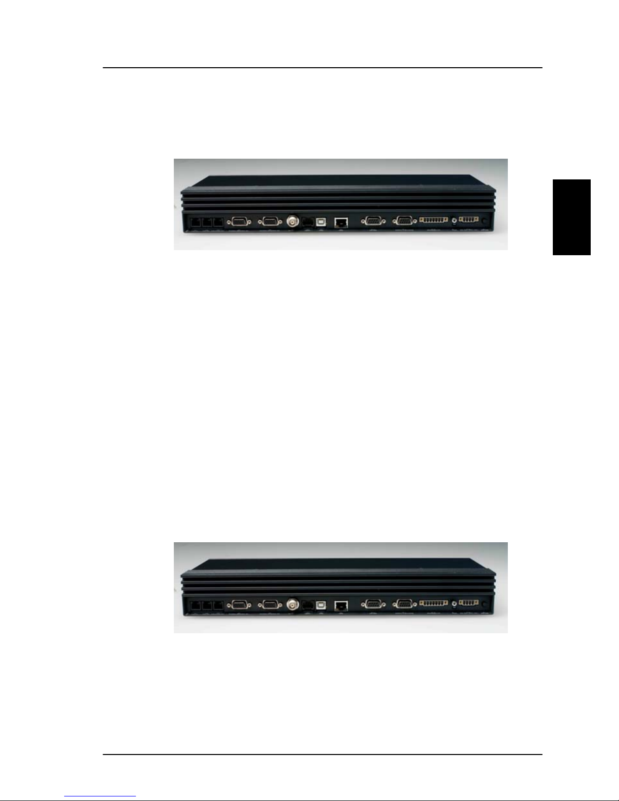
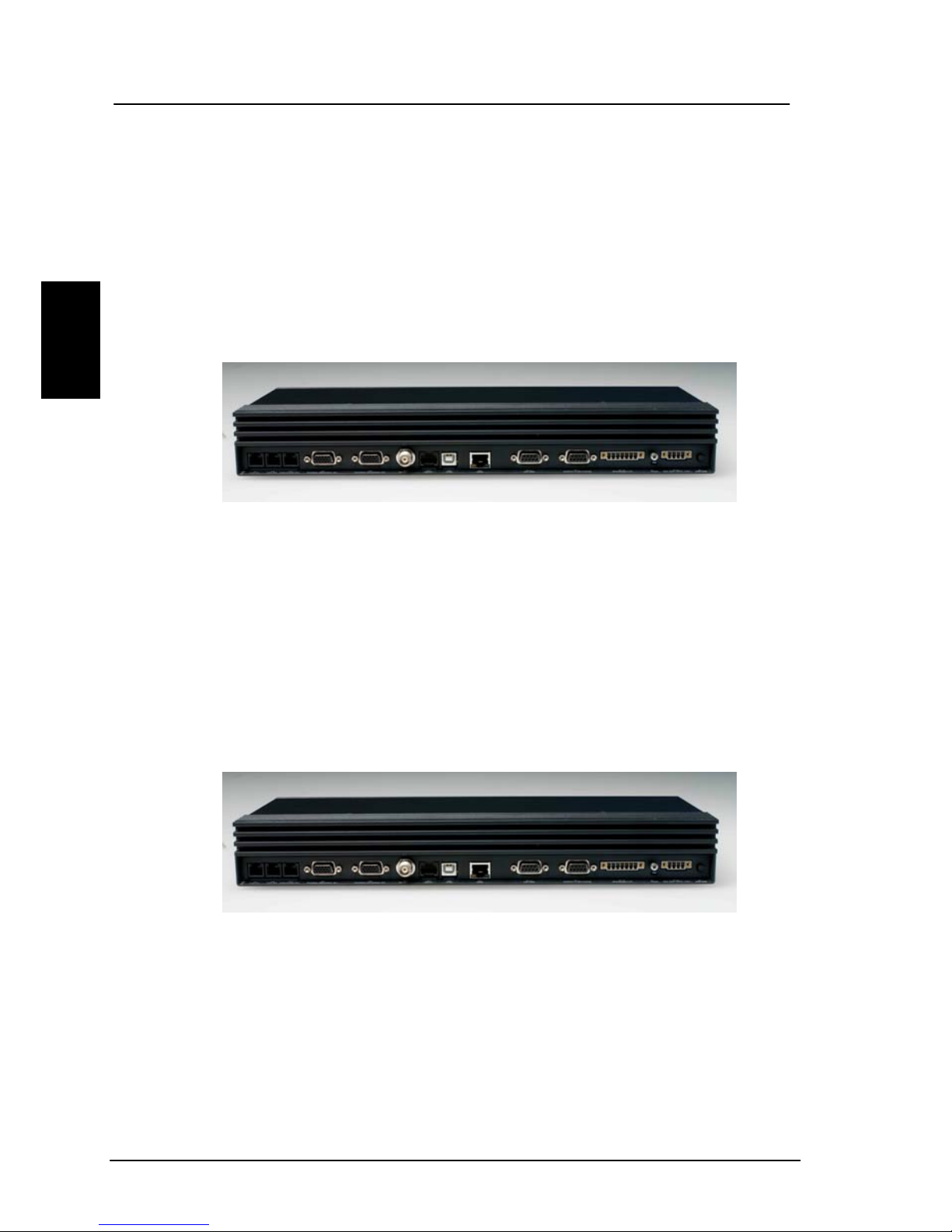
All connectors for these interfaces are found on the rear of
the Electronic Unit:
These interfaces can be used for the different Inmarsat
Fleet services.
X1 X2 X3 X4 X5 X6 X7 X8 X9 X10 X11 X12 X13
May 2005 15
Introduction Hardware Interfaces
2
2.5.1 Two Cradle/Handset interfaces
The BDU has two 4 wire handset ports with RS-485 data
control. Each Handset can be used to set-up the terminal
and it can be used to make or receive phone calls utilizing
one of the following services:
Cradle / Handset
• Speech
• 3.1 kHz audio
• mini-M voice
• Distress call
Note: At present only one port (X4) is operational.
2.5.2 Three Analogue RJ11 interfaces
The RJ11 ports as shown above can be used for connection
of analogue phones. For all interfaces the following services
can be used:
RJ11
16 May 2005

Hardware Interfaces Introduction
2
• Speech
• 3.1 kHz audio
• mini-M voice
• 9.6 kbit/s fax
The type of service used on each interface is independent
of each other and can be configured in the Routing menu.
2.5.3 ISDN interface
This interface can be used for connection of ISDN
equipment – data as well as voice/picture based equi pment
(phones, modems, terminal adapters, audio codecs, video
conferencing equipment, STE secure voice, etc.).
On F55 only one B-channel (1 x 64 kbit/s D ata) and one Dchannel (control) is used.
The F77 optionally supports two B-channels (2 x 64 kbit/s
Data ). In order to enable this service you need to enter a
special PIN code. Please contact your supplier to retri eve a
pin code. As with other services the terminal needs to be
commissioned to this service (see section 2.2).
The terminal does not support dynamic switching between
one and two B-channels. The user needs to decide to use
one or two channels before establishing the call.
ISDN
May 2005 17

Introduction Hardware Interfaces
2
Please ensure when using only one B-channel that your
ISDN equipment is configured to support one B-channel
only.
The following services may be used on the ISDN interface:
• 128 kbit/s UDI (option on F77)
• 64 kbit/s UDI
• 56 kbit/s UDI
• Speech
• 3.1 kHz audio
• mini-M voice
Like the terrestrial ISDN network the terminal offers the
possibility to have more than one device connected to this
interface. Each device can be individually addressed when
called and the service type can be selected individually.
This requires that the attached equipment supports MSN
(Multiple Subscriber Number). Depending on the brand of
equipment it may be possible to program the equipment
with more MSN's. If a device should respond to a certain
IMN number, it must be programmed in the ISDN
equipment using the IMN as MSN. Note that the equipment
will only react if both MSN as well as service type (speech,
3.1 kHz audio, 128 kbit/s, 64 kbit/s or 56 kbit/s) fit the
ISDN equipment.
Please note: When not using the 128 kbit/s service the
ISDN interface supports data transmission of one Bchannel at 64 or 56 kbit/s as opposed to two B-channels at
64 or 56 kbit/s available on the terrestrial ISDN network.
When using satellite equipment a delay is introduced due
to the satellite link. Not all standard ISDN devices are
equally good at coping with this.
18 May 2005
Hardware Interfaces Introduction
2
2.5.4 RS-232 interface
The RS-232 interface is a standard 9-pin serial ports, with
a maximum port speed of 115.2 kbit/s. The interface
supports the following service types:
RS-232
• MPDS service
• Configuration of the terminal via FleetCP software (See
section 5.1)
• Connection of a IP Router
• 64 kbit/s UDI using RS-232
When using the FleetCP program, the PC must be
connected to the RS-232 interface.
2.5.5 NMEA 0183/2000 interface
The NMEA 0183/2000 is a Gyro and Navigation interface. It
serves as a backup, if an alternative antenna without selfsteering, has to be installed.
NMEA 0183/2000
May 2005 19
Introduction Hardware Interfaces
2
Note: Interface is currently not supported.
2.5.6 Discrete I/O interface
The transceiver also has a discrete I/O interface, containing
4 configurable input/output.
Note: Interface is currently not supported.
Discrete I/O
2.5.7 USB Interface
USB - Universal Serial Bus – is an interface that allows a
single universal plug to connect PCs. USB replaces the
different serial and parallel PC connections with one
standard plug´n play port. Please note that the USB
USB Interface
20 May 2005
Hardware Interfaces Introduction
2
interface only supports the 64 kbit/s UDI service at present
time.
2.5.8 Ethernet Interface
The Ethernet interface is a RJ45 connector. It can be used
for the MPDS service. Connect a computer through a switch
or hub or connect directly using a crossover cable.
Ethernet RJ45
2.5.9 Power Connector
For connection of power, see Installation Manual.
Power Connector
May 2005 21

Introduction The Handset
2
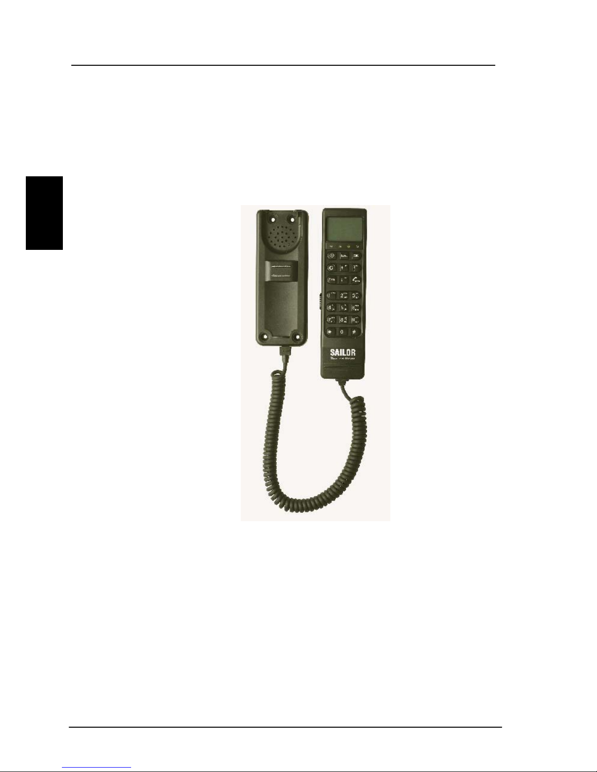
2.6 The Handset
The Handset is the primary interface for the SAILOR Fleet
system. It enables the user to dial numbers, it displays
error and status messages, and it can be used to configure
the transceiver.
The Handset is divided into 3 distinct and inter-working
sections.
1. The first is the Liquid Crystal Display (LCD) and Light
Emitting Diodes (LED) section. This section gives the
user visual indications about the operation and status
of the system.
2. The second is the Function buttons section. This
section enables the user to interact with the software
menu system of the transceiver.
3. The third is the Alpha-Numeric section. This section
enables the user to dial and perform data entry
functions into the transceiver.
In the following these sections will be described in details.
22 May 2005

The Handset Introduction
2
2.6.1 LCD/LED
As shown in the picture above, the top of the handset
contains the LCD for displaying information to the user. It
can be adjusted for contrast and is backlit for viewing in
dimly lit areas or night operations. The LCD display is
graphically shown below:
IOR:LESNAME
Ready
Te
Are
xt
a
Scroll
n
Secondary
Functions
Enabled
Dow
Alphabetic
Entry Enabled
Locked
More Options
Available
Handset
Off hook
Speaker
Enabled
Scroll Up Mailbox Signal Strength
May 2005 23

Introduction The Handset
2
The display contains a set of symbols which together with
the 4 indicators situated below the display gives continuous
indication of current status.
There are four LED’s under the LCD display (see below).
From left to right they are Power (GREEN) – Alarm (RED) –
Connected (AMBER) – Synchronization (GREEN).
POWER LED (GREEN): The Power LED indicates that the
system has power.
ALARM LED (RED): The Alarm LED will illuminate when the
system detects a fault. If the LED is lit the error can be
examined in the Alarm log. See section 4.1. 6.
CONNECTION LED (AMBER): The Connection LED will flash
when a call is ringing at the receiving end and will
illuminate steady when a connection is made.
SYNCHRONIZATION LED (GREEN): The synchronization
LED will illuminate when the system has synchronization
with a satellite.
Power
Synchronization
Alarm Connection
24 May 2005

The Handset Introduction
2
Symbol Meaning
More menu entries above.
More menu entries below
Turned on when the key has been
pressed.
Turned on when the keypad is in alpha mode.
Alpha mode is used to enter letters (for
example names in the phone book).
The value in a menu must be selected
between certain predefined values by means
of the
and keys.
The speaker. The user can turn the external
speaker on and off by pressing
. The
symbol is displayed in the LCD when on.
Short message stored at a LES – see section
4.1.4 and 4.3.23 Mailbox for further
information
The number of bars () following this antenna
symbol indicates received signal strength. Up
to 5 bars. The number of displayed bars, may
fluctuate during a call. This is due to a power
reduction, negotiated between the terminal
and the LES.
May 2005 25

Introduction The Handset
2
The handset is off hook
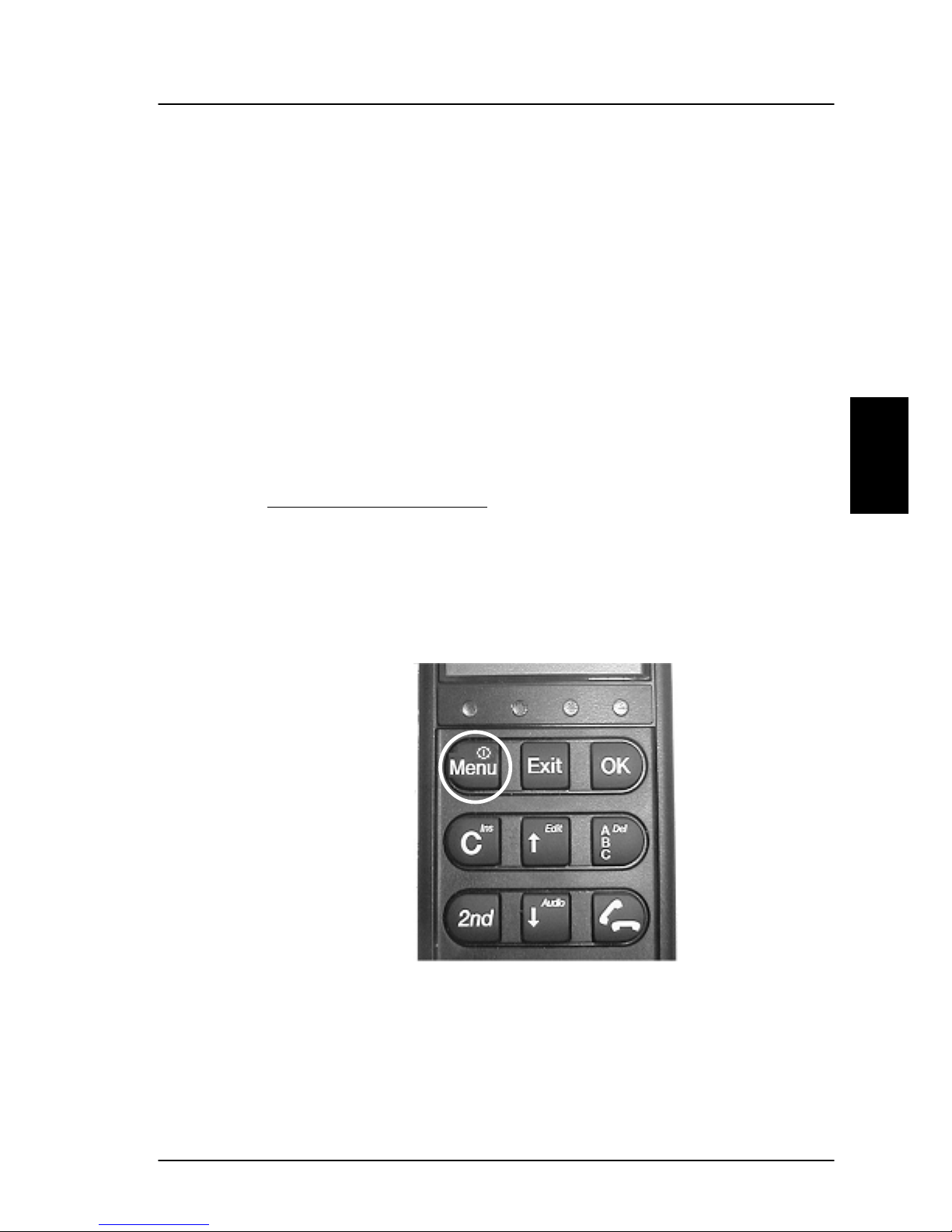
2.6.2 Function Buttons
The Function buttons, as shown above, enables the user to
enter the menu system of the transceiver and change
various settings. Each button is described in detail below.
Symbol Meaning
Enter the top level of the menu system. See
section 4.1 Menu System.
The button can also be used to switch the
terminal on and off.
To switch on the terminal press the button
shortly.
To switch off the terminal press the button for
26 May 2005

The Handset Introduction
2
a while and check that the LCD display counts
down to zero before releasing the button.
The EXIT Button: Similar in function to the
Esc-key on a PC. While in the Menu system,
pressing Exit will bring the user back one level
until the Menu is completely exited. When
asked YES or NO by the system, pressing Exit
will be interpreted as a NO response. When
entering data into the transceiver, depressing
exit will cancel the entry.
The OK button: is the inverse of the Exit
button. It is similar in function to the Enter
key on a PC. When in the main screen
display, pressing OK will enter the menu
system. While in the menus, pressing OK will
enter the selected menu. When entering data,
such as phone numbers or PIN codes, pressing
OK will accept the entry.
The Clear button: This is a dual function
button. The primary function is to clear the
last entered digit. It is similar in function to
the backspace key on a PC.
Secondary function: INSERT. This function is
accessed by first pressing and releasing the
Button and then pressing the .The
insert function is used to insert new Inmarsat
Mobile Numbers (IMN’s) into the terminal,
insert Phonebook entries, etc.
SCROLL UP button: Also a dual function
button. The primary function is to enable the
user to scroll up to menu items not shown on
the 2-line display of the LCD.
May 2005 27

Introduction The Handset
2
Secondary function: Edit. Allows users to edit
previously entered information in the
transceiver.
Toggles between normal mode and alpha
numeric mode.
Secondary function: Delete. Allows users to
delete previously entered information.
When browsing in the menu system this
button can also be used to toggle the short
codes on/off. This feature also includes
toggling displaying of the short codes on/off.
These codes can be used as shortcut to a
given menu item by pressing the short code
number using the numeric keys.
The 2nd function will be applied to the next
key. See below.
SCROLL DOWN button: Is used to scroll down
to menu items not shown on the 2-line display
of the LCD.
Toggles between on hook and off hook.
A number of keys have a 2
nd
function. A total overview of
these is given in the following table.
Key Function
Recalls the last dialed number.
28 May 2005

The Handset Introduction
2
Not used
Shortcut to the area selection submenu, see
section 4.1.2 Area.
Not used.
Not used.
Not used.
Turn speaker in the cradle on/off.
Shows C/No “signal strength” in the display.
Pressing returns to the previous state.
Sets the brightness of the LED's. See section
4.3.16 below LED Dimm.
Short cut to the Help desk menu. See section
4.1.5 below Help Desk.
Insert an entry (for example in phone book)
Edit an existing entry (for example in phone
book)
Delete an existing entry (for example in
phone book)
May 2005 29

Introduction The Handset
2
2.6.3 Alpha-Numeric Buttons
The keypad can be in normal (numeric) mode or alpha
mode. Normal mode is used to enter digits (phone
numbers) whereas alpha mode is used to enter letters
(names in the phone book). The
is used to switch
between the two modes and the display indicates if in
alpha mode. In alpha mode each of the numeric keys (plus
) can be used to select between subsets of the alphabet
(and certain special characters) by pressing the key a
number of times until the wanted letter/character is shown
on the display. To insert the letter C it is necessary to press
3 times in alpha mode. Below is an overview of the
relevant keys in alpha mode. When browsing in the menus
can be used to toggle short codes on/off. These codes
can be used as shortcut to a given menu item by pressing
the short code number using the numeric keys.
Key Toggles between when pressed in alpha mode
- ? ! , . : ’ $ ( ) + / 1
A B C 2
30 May 2005

The Handset Introduction
2
D E F 3
G H I 4
J K L 5
M N O 6
P Q R S 7
T U V 8
W X Y Z 9
Move cursor (forced)
<space>
May 2005 31

Introduction Distress Cradle
2
2.7 Distress Cradle
NOTE: The Distress cradle is only available with the
TT-3084A SAILOR Fleet77 system.
Besides being the base for the handset, the Distress cradle
is also where a Distress call is initiated or ended. A speaker
for hand free operation is located in the lower left side of
the cradle. Press
to toggle the speaker on/off.
The cradle includes 3 LED’s ant two buttons.
Distress button: The Distress button, protected by plastic
glass, is used to initiate a Distress call. See section 3.4.1
How to make a Distress call.
Distress Stop button: Is used to abort a distress call
before the connection is established.
Power On LED: Indicates that the system is powered on.
Priority Call LED: Is lit whenever a priority call is in
progress (distress, safety or urgency). See section 4.2.5
32 May 2005

Distress Cradle Introduction
2
Priority calls.
Distress Test LED: Is lit when a distress test is
performed. See section 4.3.18 Distress Test.
May 2005 33

Get ready to make a call Getting started
3
3 Getting started
3.1 Get ready to make a call
3.1.1 How to power on the system.
The system can be powered on from the BDU or from the
handset.
Power on from Handset
:
The handset power button is placed in the upper left corner
of the handset. See the figure below. To power on the
system just press the button.
May 2005 35

Getting started Get ready to make a call
3
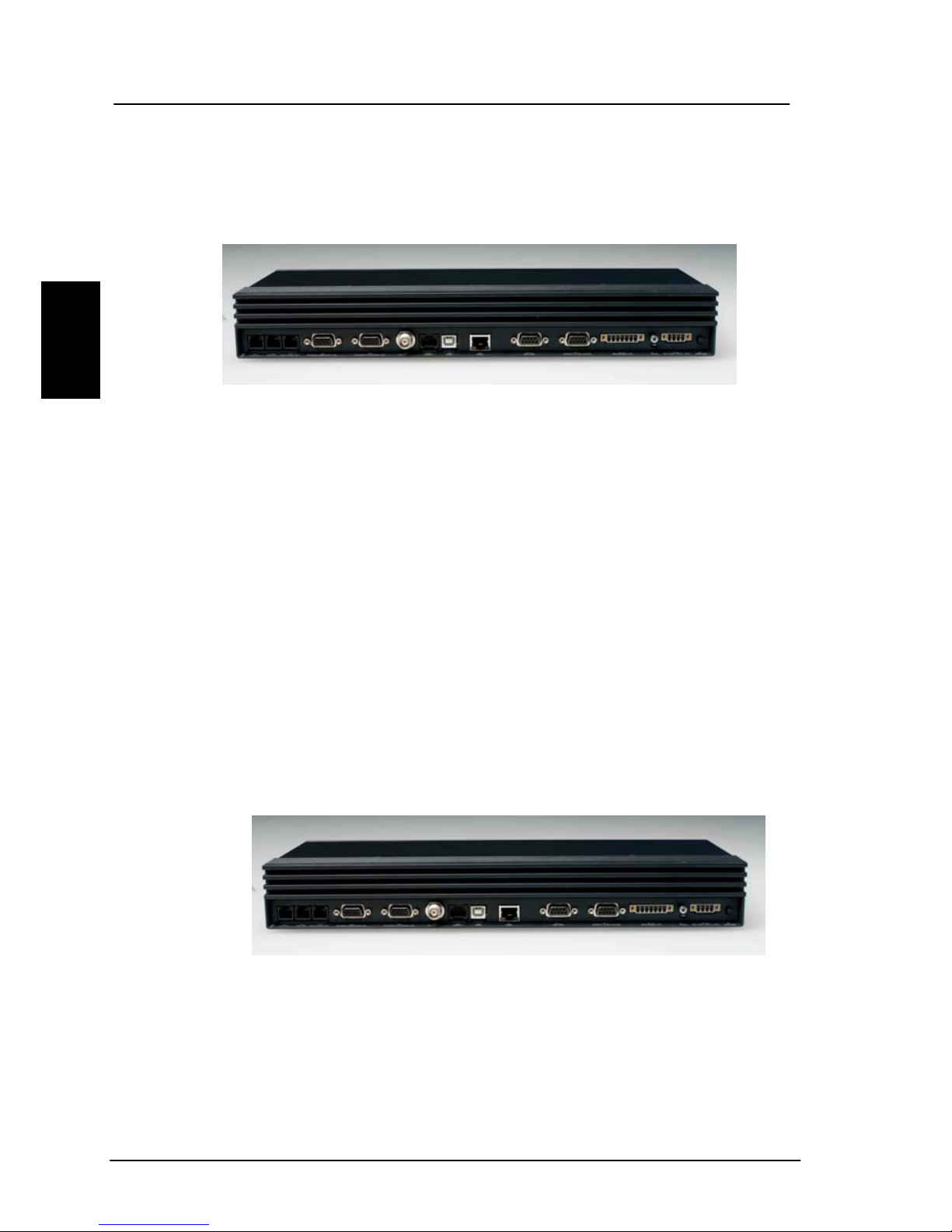
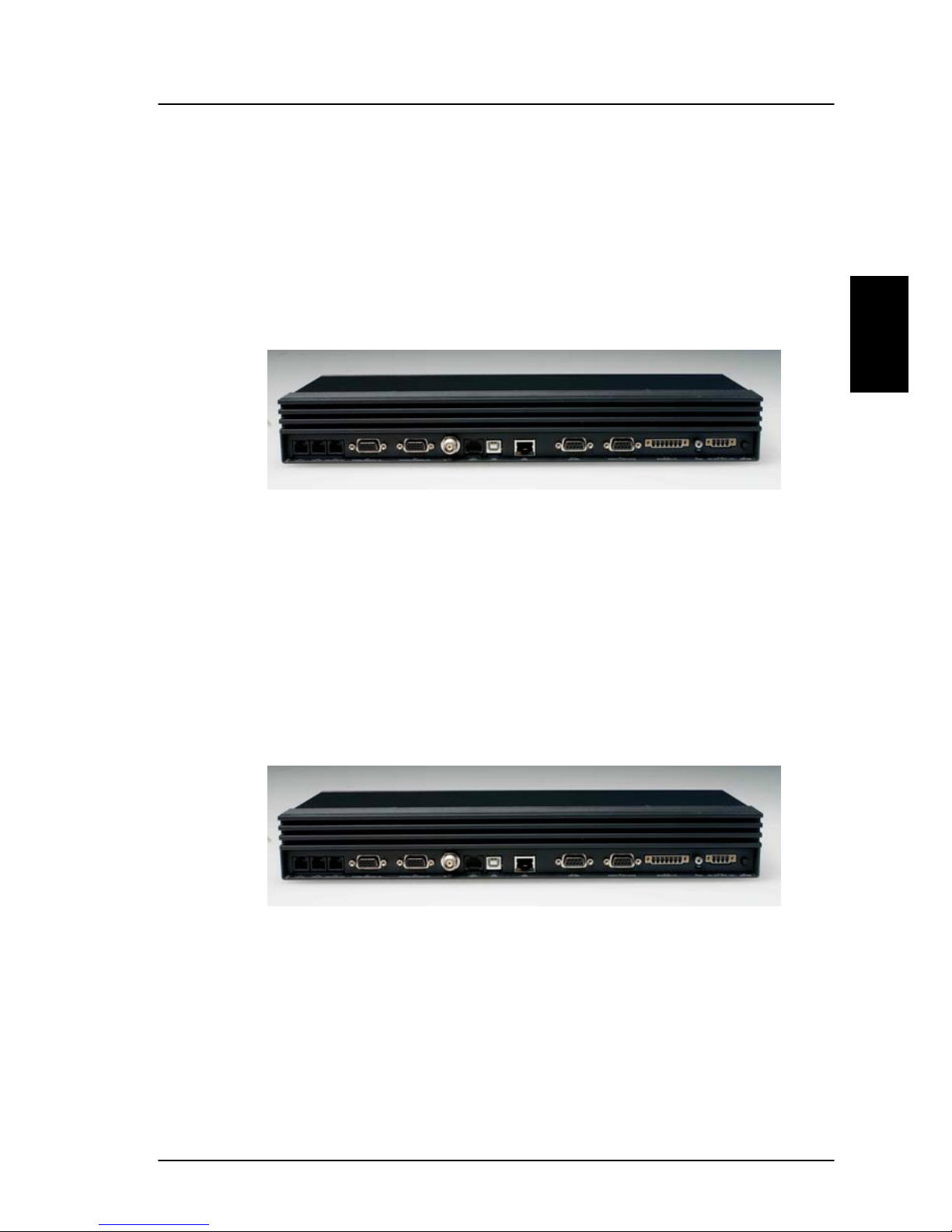
Power on from BDU:
The BDU power button is placed on the back panel of the
BDU. See figure below.
Press and hold the power button for a few seconds or until
the green LED on the front of the terminal lights up.
The display and all LED's on the handset and the cradle will
light up for a few seconds.
Power Button
Power LED
36 May 2005

Get ready to make a call Getting started
3
Below is an example of the normal readout of the handset
display, while the BDU is booting.
The system may stay in the “Wait for GPS” state for an
extended period, if e.g. the antenna has been turned off for
a long time or there is not a free view to the GPS satellites.
The time to get the GPS position may be several minutes.
Initialising
AORE:
Wait for NCS
AORE:
Wait for NCS
AORE:
Wait for GPS
AORE: LESNAME
READY
May 2005 37

Getting started Get ready to make a call
3
When the display reads “READY” as shown above, the
system is ready to make and receive calls.
3.1.2 How to power down the system.
The system can be powered off from the BDU or from the
handset.
Power off from handset
:
The handset power button is placed in the upper left corner
of the handset. To power off the system just press and hold
the button. After a few seconds the LCD display starts a
count down to zero. When the countdown is finished the
display shows the message “Release Power Button”. When
the button is released the system will power off.
Power off from BDU
:
Press and hold the power button for a few seconds, until
the handset display shows the message shown below.
Let go of the button and the terminal will shut down.
Note: Wait at least 5 seconds after a power down,
before trying to power up the system again.
Thrane F55
Goodbye
Thrane F77
Goodbye
38 May 2005

Use of PIN codes. Getting started
3
3.2 Use of PIN codes.
Access to some of the terminals functionalities are
restricted by a PIN code. Two different kinds of User PIN
codes are used in the system: One PIN for the Super User
and one for the Service User.
Common for both PIN types is that the length must be
between 4 and 8 digits and that they contain digits
between 0 and 9.
The normal everyday user (Normal User) can make and
receive calls, access the phonebook, choose an ocean
region and a default LES, read the alarm log and status
and make a call from the Helpdesk. For a description of
these functions see section 4.1 Menu System. All other
setup changes have to be carried out by a Super User or a
Service User.
Super User PIN
The Super User has the same rights as the Normal User. In
addition the Super User can access the Super User menu.
See section 4.3 for details. A Super User will typically be a
person responsible for setting up and maintaining the
system. It is only possible to have one Super User PIN
code. If the PIN is entered incorrectly 3 times, the PIN
becomes blocked. A blocked Super User PIN, can only be
unblocked by a PUK code or the Service User. The factory
PIN code is ‘12345678’.
Service User PIN
The Service User has access to all functionality in the Fleet
system, which is accessible through the handset. Only T&T
and/or the supplier of the equipment normally know this
PIN. If the PIN is entered incorrectly 3 times, the PIN
becomes blocked. Only a PUK code can unblock a blocked
Service User PIN. For use of the service menu you are
May 2005 39

Getting started Normal calls
3
referred to the “TT-3084A SAILOR Fleet77, TT-3086A
SAILOR Fleet55, Installation Manual”.
STU PIN and 128K PIN
Pin codes must be retrieved from your distributor in order
to enable the STU functionality (Secure Telephone Unit) or
the 128 kbit/s service. Please refer to section 4.3.26 and
5.1.2 to see how to enable the service.
3.3 Normal calls
3.3.1 Call from handset
Any call made from the system, uses a service type (miniM voice, Speech or 3.1 kHz audio).
The service type used for a call from the handset is the
service type configured as default for this handset and the
LES operator used will be the default LES operator.
When making calls from the handset just type in the phone
number as if you were making an international call (with
prefix for automatic international calls equal to 00).
E.g. to dial the number of Thrane & Thrane (+45
39558800), press the number:
for international calls for country code then
, followed by or . The
display on the terminal handset will show how the call
proceeds.
40 May 2005

Normal calls Getting started
3
You hang up by pressing . During and after a call, the
display will show how long the call lasted.
Example:
The Phone Book can also be used to initiate a call, either by
selecting an entry in the phone book or by usi ng the short
code. See section 4.2.1 for details.
Connected:
00:01:59
3.3.2 Calling the terminal
Calling the terminal or a device connected to the terminal
is similar to making international calls. The specific IMNnumber (a terminal may have more numbers as different
services exist and more devices may be connected to the
different hardware interfaces of the terminal) has to be
preceded by one of the five possible international access
codes. This depends on whether you know which area the
terminal is within or not:
870: Area of terminal not known
(Requires that the LES support Mobility Management).
871: AORE
872: POR
873: IOR
874: AORW
To call the IMN-number on a terminal situated in IOR dial
00873 followed by the IMN number
May 2005 41

Getting started Distress call
3
3.4 Distress call
Please note: The distress functionality is available on
Fleet77 systems only.
A distress call is an automated way of calling for help
(SOS). A distress call from the Fleet77 system is a voice
call, which means that the call will be connected to an
operator at the RCC (Rescue Co-ordination Center). When
the distress call is connected, the ships position and the
MES ID are sent to the RCC. This enables the center to
identify and locate the ship.
3.4.1 How to make a Distress call.
To initiate a Distress call, press and hold the Distress
button on the cradle. The button will flash with an interval
of 1 second and the cradle buzzer will beep with the same
interval. After 5 seconds, the button light will become
constant and the buzzer will stop beeping. Any ongoing
calls will be pre-empted, unless it is another Distress call.
During the preemption the handset display will show the
message ‘DISTRESS Wait’.
If the distress button is released within the 5 seconds, the
distress call will be canceled and the terminal will return to
its normal state.
After the preemption if any the handset will display the
message ‘Select LES’. Scroll through the LES list with the
keys and select the LES by pressing . If a LES
is not selected within 15 seconds or one of the 2 keys
is pressed, the call will be initiated through the
LES pre-configured in the "Distress LES". If no Distress LES
is configured, the Default LES will be used instead. If the
42 May 2005

Distress call Getting started
3
Default LES is also not configured, the NCS redirects the
call to an appropriate LES.
Note: If a Distress LES is not defined for each Ocean
Region, an alarm will appear and the entry ‘Distress
LES is not selected in all Ocean Regions’ will be
added to the alarm log.
To cancel the Distress mode, press and hold the ‘Distress
Stop’ button, after the button light becomes constant, but
before the 15 seconds timer runs out. The display will then
show ‘Distress Aborted’.
If the Distress call is continued, the handset will display
‘DISTRESS - Calling’. The call will be connected to the RCC,
the handset will display ‘DISTRESS - Connected’ and the
cradle LED ‘Priority call’ will light up. The user can now talk
to the RCC operator.
The ‘Distress’ button light will stay lit, until the call is
aborted.
3.4.2 Distress call failure.
If the Distress call fails to connect, due to a system
malfunction (BDU, ADU, satellite or terrestrial), the light on
the cradle ‘Distress’ button will turn off and the system will
return to a normal state.
3.4.3 Distress and Priority call to the ship
The RCC operator can generate a distress alert priority call
to the ship. The ‘Priority Call’ LED will start flashing on all
cradles and if the call has distress priority, the buzzer will
beep with 1 second intervals.
May 2005 43

Getting started MPDS connection
3
Any calls with lower priority including MPDS sessions will
be pre-empted and a busy tone will be heard.
The distress and priority call is answered by picking up a
handset or by pressing
after which the ‘Priority Call’
LED will light steadily and the buzzer stops beeping.
The ‘Priority Call’ LED will turn off when the call is
terminated.
If the call is not answered by the ship, but terminated by
the RCC, the Alarm LED turns on to indicate that there was
an unanswered distress alert or priority call. Details about
the alarm can be checked in the alarm log.
3.5 MPDS connection
Please note: The MPDS service is only available on
Fleet55 systems when the vessel is positioned inside
an area with Spot Beam coverage. On Fleet77
systems the service is available in global beam.
Mobile Packet Data Service (MPDS) is a service that allows
the mobile user to remain “always connected” to the
Internet with billing based on the amount of data
transferred rather than the time spent online. This makes
the service an ideal and cost effective solution for
applications like Web browsing, email services, IP/LAN
connectivity and small to medium size file transfer. The
MPDS service provides a 64 kbit/s shared channel.
While in MPDS mode the TT-3084A is flagged busy in the
Inmarsat network. This means that the Fleet system is not
able to receive any incoming calls until it returns to normal
idle mode. However, the user can enable the Call Waiting
Notification feature. This allows the system to recei ve voice
calls during an ongoing MPDS call. For further information
about this feature, see section 3.5.1.
44 May 2005

MPDS connection Getting started
3
Paragraph 5.2.1 and 5.3 contains a description of how to
setup an MPDS connection using your PC.
3.5.1 Call waiting
As indicated in the previ ous secti on the user can enabl e the
Call Waiting Notification in order to receive incoming voice
calls during an MPDS session. The enabling can optionally
be restricted to specific phone numbers.
The 4-wire and 2-wires interfaces can be configured for
usage for the Call Waiting Notification. When the
notification arrives, the user is notified by a special ringing
tone and a message is shown in the display if the 4-wire
handset is selected for the service.
In case of an incoming call during an MPDS session with
the Call Waiting Notification enabled, the user has three
options:
1. The user can reject the pre-emption of the MPDS
connection by pressing “*” or “Exit” on the 4-wire
handset (if enabled) or by taking an enabled 2-wire
phone off hook, pressing “*” and placing the phone on
hook again. The ringing stops on all handsets that are
configured for the service.
2. The user can accept the pre-emption of the MPDS
connection by pressing “OK” or “#” on the 4-wire
handset (if enabled) or by taking an enabled 2-wire
phone off hook, pressing “#” and placing the phone on
hook again. The MPDS session is now deregistered and
the call gets through after a short while. The phone(s)
to which the call is routed starts ringing and the call
can be answered. Note that the call can be answered
May 2005 45

Getting started ISDN Connection
3
on another interface than the interface that was used
to accept the call – e.g. a fax will normally only be
routed to a specific RJ11 connector and not the 4-wire
handset.
3. The user may also choose to do nothing. After a certain
time the notification stops and the pre-emption of the
MPDS connection is implicitly rejected, if no other lines
have accepted the notification.
Configuration of the Call Waiting notification is described in
paragraph 4.3.28.
3.6 ISDN Connection
Please note: The ISDN service is only available on
Fleet55 systems when the vessel is positioned inside
an area with Spot Beam coverage. On Fleet77
systems the services are available in global beam.
The Integrated Services Digital Network (ISDN) enables a
bi-directional transmission of data to and from terrestrial
ISDN networks.
The Fleet55 and the generic Fleet77 supports a single Bchannel (1 x 64 kbit/s Data) and one D-channel (control).
The Fleet77 optionally supports two B-channels (2 x 64
kbit/s Data ). In order to enable this service a pin code is
needed. This pin code can be retrieved from your
distributor. As with other services the terminal needs to be
commissioned to the 128 kbit/s service.
46 May 2005

ISDN Connection Getting started
3
The terminal does not support dynamic switching between
one and two B-channels. The user needs to decide whether
to use one or two channels before establishing the cal l. The
Fleet77 128kbit/s service does not support mixed fixed and
mobile originated calls, mixed UDI and voice calls or the
ability to lay down one of the B channels dynamically.
For fixed originated calls, the terrestri al user is expected to
dial the same INM number twice for each of the 64kbit/s
calls.
Please refer to section 2.5.3 for additional information
about the ISDN interface.
The mobile ISDN service is charged by connection time
that makes the service feasible for transmissions that
require a large data throughput.
Section 5.2.2 contains a description of how to setup an
ISDN data connection on your PC.
May 2005 47


Menu System Operation
4
4 Operation
4.1 Menu System
This section describes the functions in the menu system,
available to all users.
The menu points handling Distress/Priority call
options are only present on Fleet77 systems.
The menu is accessed by pressing
. Scrolling through
the menus is done by the keys
and . Pressing
will enter the selected menu. Pressing
will exit to the
previous level in the menu system. A point in the menu
system can also be reached by pressing
and a number
corresponding to the entry level, e.g. pressing
will
access the 'Alarm Log' menu. Pressing
in the menu
system will toggle shortcut numbers on and off.
The level of access to the menus is divided into 3 groups of
users. A Normal User, a Super User and a Service User.
The Normal User has access to normal everyday functions.
A Super User has the same rights, but can additionally
access different setup menus. The Service User menu can
only be accessed by the supplier or Thrane & Thrane. The
Super User and Service User menus are protected by PIN
codes.
A complete Menu Tree can be found in Appendix A - Menu
Tree.
May 2005 49

Operation Menu System
4
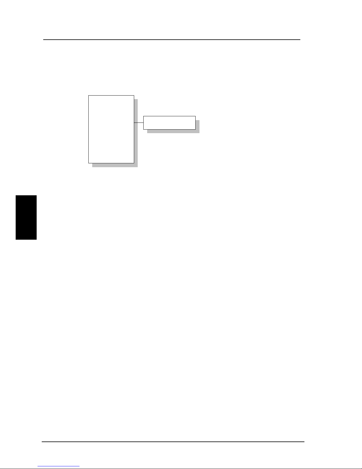
4.1.1 Phonebook
The terminal PhoneBook contains 99 entries. Each entry
contains the following information:
Phonebook
Area
LES
Mailbox
Helpdesk
Alarm log
Status
Super User
Service User
01 TT
02 TT2
01 539558800
02 5395588xx
Hint
Press
to view the
last nine digits of the
phonenumber
• Name
• Telephone number
• Short code
The telephone number includes call prefix for automatic
calls and international access code. The telephone number
can hold up to 22 digits.
The name can hold from 0 to 16 characters.
The short code can be used for quick access when dialing.
To use the short code, press
<short code> and
press
again to dial.
The list of entries in the phone book is sorted according to
short code.
An entry in the phone book is displayed as a short code
and a name if in alpha mode or as a short code and a
telephone number if in normal mode.
Use
to select an entry and press . The phone
number is displayed.
50 May 2005

Menu System Operation
4
Press or to dial.
Pressing
when the wanted number is displayed, will
invoke the priority menu. Use the
keys to select
call priority (only on Fleet77). Press
or to initiate
the call. For more information on how to make priority
calls, see section 4.2.5 Priority calls.
Inserting an entry in the phone book from within the phone
book menu, is done in the following example. In this
example the number to T&T, 004539558800, with short
code 14 is inserted.
THRANE
Editing or deleting an entry is done by selecting the entry
in the phone book and pressing
and
respectively.
May 2005 51

Operation Menu System
4
4.1.2 Area
The Area menu is used to select ocean region and has got
the following list of possible choices:
Phonebook
Area
LES
Mailbox
Helpdesk
Alarm log
Status
Super User
Service User
None
*Automatic
W-Atlantic
E-Atlantic
Indian
Pacific
Spare1
Spare2
Spare3
Spare4
• None
• Automatic
• W-Atlantic
• E-Atlantic
• Indian
• Pacific
• Spare 1
• Spare 2
• Spare 3
• Spare 4
The selected area is marked with an *. If Automatic is
selected the terminal will determine the area by scanning
the sky and selecting the satellite with the best C/No. The
selection is changed by choosing an area and then pressing
. Consult a coverage map to see the coverage areas for
each ocean region.
52 May 2005

Menu System Operation
4
4.1.3 LES
The LES list contains a list of those LES operators, which
may be selected as gateway to the terrestrial network. The
last used LES will be marked with * and this LES will also
be the first LES tried next time the terminal is logged on.
Use
to select. The Area selected in secti on 4.1.2 Area,
will decide which LES's will be available for selection.
See section 4.3.25 LES Config for further information about
LES configuration.
Phonebook
Area
LES
Mailbox
Helpdesk
Alarm log
Status
Super User
Service User
001: Comsat
002: BT
003: KDD
004: Telenor
005: OTE
006:
007:
008: FRAC
009: ST12
.
.
.
.
May 2005 53
Operation Menu System
4
4.1.4 Mailbox
The Mailbox feature is not supported by all LES operators.
The feature handles messages sent from the LES operator.
If a call is made to a terminal, which is busy, switched off,
etc. the LES operator may offer the facility to record a
short message. When the terminal again becomes
operational a message is sent indicating that the LES
operator has recorded a short message for the terminal.
The
symbol in the handset display indicates the
presence of such messages.
Each message can be seen in the Mailbox menu and
contains the following information:
Phonebook
Area
LES
Mailbox
Helpdesk
Alarm log
Status
Super User
Service User
List Empty
• LES Access Code
• Service type (voice, fax, data).
To view an entry, select the message and press
. See
how to delete a message in section 4.3.1
54 May 2005

Menu System Operation
4
4.1.5 Help Desk
The Help Desk is a secondary phone book that can be
used for storing up to 10 support phone numbers (e.g.
Thrane & Thrane support centers).
Editing/inserting and deleting entries is done in exactly the
same way as with the phone book, but it can onl y be done
from the super user menu. Each entry contains a phone
number, name of the entry, and a LES access code.
Phonebook
Area
LES
Mailbox
Helpdesk
Alarm log
Status
Super User
Service User
H.Desk empty
Press to access
the menu directly.
May 2005 55

Operation Menu System
4
4.1.6 Alarm Log
The Alar m Log, logs all the alarms in the system (cf. 6.1
List of Error messages). From this menu, the alarm can be
viewed only. To clear the alarm list see section 4.3.19.
Scroll through the list, using the
keys. A * in front
of the Alarm name, indicates that the alarm is still active.
Select an alarm for viewing, by pressing
. Each entry
for an alarm contains an alarm description and the time
and date when the alarm occurred. See section 6.1 for a
list of alarms.
The alarm log can contain up to 20 entries. The log will
wrap around when the log is full.
Phonebook
Area
LES
Mailbox
Helpdesk
Alarm log
Status
Super User
Service User
View alarms
Clear alarms
*FEU
*POSITION
.
.
.
56 May 2005

Menu System Operation
4
4.1.7 Status
The Status menu has got the following sub menus:
Phonebook
Area
LES
Mailbox
Helpdesk
Alarm log
Status
Super User
Service User
C/NO
Transceiver
RF Block
Bulletin
Antenna
GPS Info
• C/No
• Transceiver
• RF block
• Bulletin
• Antenna
• GPS
C/No:
Choosing C/No will display the signal strength in dBHz.
Pressing
will return to the previous state.
Transceiver
Release date: Software release date.
Unit Type: Type of unit.
Serial No.: T&T serial number.
ISN: Inmarsat serial number.
PCB No.: Serial number of main CPU board.
Forward ID: Terminals Forward ID number.
SW Ver.: Software version.
RF Block
RX Frequency: Receiving frequency in MHz.
TX Frequency: Transmitting frequency in MHz
May 2005 57

Operation Menu System
4
Freq. offset: Frequency offset between 0-1500 Hz.
Acc. offset: Acc offset between 0-1500 Hz.
AGC: AGC between 0-1024.
Gain: Gain between 0-256.
TX level: TX level equals LOW or OK.
Lo1-Lo3: Lox In or Out of lock.
Temperature: Temperature in deg. C.
Power mode: Power mode in sleep or normal.
Bulletin
Ocean Region: AORW, AORE, POR or IOR.
NSR state: Not initialized, initializing or initialized.
Type: Mini-M or NG
Bulletin page 1-6: Page 1 to 255 or Invalid.
Spot beam ID: Spot beam ID number between 1-255.
SU CC Rxed: Between 0000-9999.
SU CC Txed: Between 0000-9999.
Antenna
The antenna information is divided into two parts: F
ront
E
nd Unit and Antenna Control Unit and is primarily
intended for service use.
FEU: Unit type:
Serial no.:
SW version:
Mode:
Power:
Temperature:
Cable loss:
Reset count:
Date:
ACU: Unit type:
Serial no.:
State:
Input power:
58 May 2005

Menu System Operation
4
Control Version:
Loader ver.:
FPGA ver.:
SU ver.:
RX2 ver.:
Loader CRC:
Control CRC:
FPGA CRC:
Config CRC:
GPS
PositionInfo: Not ready or Latitude and Longitude.
Heading: Not ready, heading 0-360 degrees or
Heading N/A Low speed (If speed is
equal to or below 1 knot).
Speed: Not ready or speed in knots.
UTC Time: Not ready or YYYY:MM:DD HH:MM:SS
Internal GPS: Not ready or Active and ready.
External GPS: Not ready (for future use).
4.2 Call functions
4.2.1 Call using phone book
The phone book can be used to initiate a call, either by
selecting an entry in the phone book, and then pressing
or , or by using the short code. In the latter
situation press
followed by the short code. Pressing
afterwards will establish the call. Pressing instead
will show the actual number and the call can then be
established by pressing
or . Pressing instead of
and , will invoke the priority menu. Use the
keys to select call priority. Press or to
initiate the call. For more information on how to make
May 2005 59

Operation Call functions
4
priority calls, see section 4.2.5 Priority Calls. Short code 0
contains the last dialed number, thus
or
followed by will redial the last number.
4.2.2 Call from handset connected to RJ11
Making a call from a (normal 2-wire PSTN) phone
connected to one of the three analogue RJ11 interfaces is
done in the same way as a call from the handset. Just keep
in mind to press the
key in order to signal the terminal,
that the number is complete.
Calling Thrane & Thrane in Denmark (country code 45) is
done by pressing the following keys on the phone:
When using one of the RJ11 analogue interfaces please
make sure that the selected interface is configured for a
service, which supports voice (mini-M voi ce, speech or 3.1
kHz audio). See section 4.3.2.
The display on the terminal handset will show how the call
proceeds.
After hanging up (on the 2-wire phone), the display will
show how long the call lasted.
4.2.3 Call from an ISDN phone
Making a call from a phone connected to the ISDN interface
is done in the same way as a call from the handset. Just
keep in mind to press the key in order to signal the
terminal, that the number is complete.
60 May 2005

Menu System Operation
4
Calling Thrane & Thrane in Denmark (country code 45) is
done by pressing the following keys on the phone:
The display on the terminal handset will show how the call
proceeds.
After hanging up (on the ISDN phone) the display will show
how long the call lasted.
4.2.4 Fax call
Note: This procedure is currently not functional in
F55.
Fax calls can be made whether or not the fax has got a
keypad.
Making calls from a fax (with keypad) connected to one of
the three analogue RJ11 interfaces are done as
international calls followed by
. Calling Thrane & Thrane
in Denmark (country code 45) press the following keys on
the fax:
Please make sure that the selected analogue RJ11 interface
is configured for a service which supports fax (9600 fax or
3.1 kHz audio).
The display on the handset will show how the call proceeds.
After hanging up, the display will show how long the call
lasted.
May 2005 61

Operation Call functions
4
4.2.5 Priority calls
Please note: The Priority Call functionality is available
on Fleet77 systems only.
A priority level can be selected when making a call. The
priority levels is listed in the table below, where Routinepersonal is lowest priority and Distress is highest.
Call Type Priority level
Routine-personal 0-
Routine-professional 0+
Safety 1
Urgency 2
Distress 3
To make a Routine-personal call vi a the Default LES, press
the number and initiate the call by pressing
or .
To make a Routine-personal, Routine-professional, Safety
or Urgency call using default LES, press the number
followed by
. Use the keys to select call
priority. Press
or to initiate the call.
To make a priority call using a LES different from the
default LES, press the number followed by
. Use the
keys to select call priority. Press to open the
LES list. Use the
keys to select a LES and press
, or to initiate the call.
62 May 2005

Menu System Operation
4
A Distress call can only be made by pressing the Distress
button on the Distress Cradle. See section 3.4.1 How to
make a Distress call.
4.2.6 Internal calls
It is possible to make internal calls between any RJ11 (2
wire) interface. The call is initiated by pressing the
interface code in the table below and then
Interface Interface Code Interface port
RJ11 #1 2 X1
RJ11 #2 3 X2
RJ11 #3 4 X3
ISDN 5 X7
May 2005 63

Operation Super User functions
4
4.3 Super User functions
This section contains a description of the items in the
Super User Menu. Please remember that the
button can
be used to toggle short codes on and off.
4.3.1 Call Logs
The Call log menu has got the following sub-menus
------------Call logs
Routing
Data Setup
Contrast
Logged Calls
T
otal time
T
otal MPDS
Clear log
Start time
Phone number
Duration
OID
Area
LES acc.code
T
NID
CallPriority
Received
T
ransmitted
T
otal
• Logged calls
• Total Time
• Total MPDS
• Clear log
By entering the Logged calls menu it is possible to inspect
information about each of the outgoing calls made on the
terminal. The following information is logged for each call:
64 May 2005

Menu System Operation
4
• Start time of call.
• Destination phone number.
• Duration of call
• Originating ID. (Description of service used).
• Ocean region used.
• LES access code.
• Terrestrial network identity (always 0).
• Call priority.
• Number of received bytes in MPDS.
• Number of transmitted bytes in MPDS.
• Total number of bytes in MPDS.
Total Time shows the total accumulated call time since
last reset.
Total MPDS shows the total accumulated number of bytes,
used in MPDS sessions.
The call log can be cleared by selecting the Clear Log
menu. Press
to clear or to abort.
The call log can contain up to 500 entries. After that it will
do a wrap around and start overwriting the oldest entry.
A warning will be generated when the call log contains
more than 470 entries. You may then back up your log
data by Fleet CP PC software. If you also clear the log, you
will get a warning again when 30 entries are left.
May 2005 65

Operation Super User functions
4
4.3.2 Routing
The Routing menu is used to associate the services with
one or more interfaces. The menu has been divided into a
number of submenus – one for each interface:
Call Logs
Routing
Data Setup
MiniM voice
{IMN}#
--------------Speech
{IMN}
---------------
3.1KHz audio
*{IMN}
--------------.
.
.
Handset #1
RJ11 #1
RJ11 #2
RJ11 #3
ISDN
RS232 #1
USB
Ethernet
• Handset #1
• RJ11 #1
• RJ11 #2
• RJ11 #3
• ISDN
• RS-232 #1
• USB
• Ethernet
Note 1: The IMN-number has to be defined, before
the service can be routed to an interface. The service
will not be listed in the routing table, unless it has an
IMN-number defined.
Note 2: Some users want the IMN number to reflect
the corresponding telephone number. In this case
the user should EDIT the default IMN number. The
INSERT function is only for adding additional IMN
66 May 2005

Menu System Operation
4
numbers. (or for creating the first IMN in case the
list is empty).
When entering one of the above submenus it is possible to
scroll through a list of all relevant IMN-numbers for the
interface. In the handset menu, you will see all IMN’s
associated with voice: mini-M voice, Speech, 3.1 kHz
audio. The ISDN menu has the same, but in addition also
the services 64 Kbit/s and 56 Kbit/s and if enabled 2x64
Kbit/s and 2x56 Kbit/s. If an IMN has an incoming route to
an interface it is marked with “*”. If it has an outgoing
route to an interface, it is marked with a “#”. It is possible
to change the routing-status for each IMN to the opposite
by pressing
for incoming and for outgoing.
It is possible to route one IMN to more interfaces. E.g. an
IMN can be routed to all three RJ11 interfaces at the same
time. This will make it possible, to have an incoming call
being routed to three 2-wire phones simultaneous.
Below is a table giving an overview of the routing matrix in
the Fleet system. The X's indicates which service that can
be routed to the specific interface.
May 2005 67

Operation Super User functions
4
Service Interface
Handset RJ11 RS-232 / ISDN Etherne
t
(1, 2 & 3) USB
Mini-M voice X X X
9600 fax X
Speech X X X
3.1 kHz audio X X X
64 Kbit/s X X
56 Kbit/s X
MPDS X* X
2x64 Kbit/s X
2x56 Kbit/s X
* Please note that MPDS can only be associated with
RS-232 and Ethernet – not the USB interface.
4.3.3 Data setup
This menu is used to setup baudrate and dataflow control
for the two RS-232 interfaces. The following settings can
be configured.
Baudrate: 115200-1200
Flow control: None | Xon/Xoff | Hardware
Routing
Data setup
Contrast
Ring Setup
Baudrate
Flow control
+++mode
Result codes
115200
57600
38400
.
.
1200
68 May 2005

Menu System Operation
4
+++mode: Disabled | Enabled
Result codes: Disabled | Enabled
4.3.4 Contrast
Call logs
Routing
Data setup
Contrast
Contrast
4.====
Press to Adjust
The display contrast of the two handset can be adjusted.
To change the contrast level, select the Contrast menu
and adjust the value with
and . Setting can be
adjusted between 1 and 8. Default value is 4.
May 2005 69

Operation Super User functions
4
4.3.5 Ring setup
Ring Volume
Ring Cadence
Ring Volume
4.====
Press to Adjust
Ring Setu p
Key Beep
Set UTC Ti me
Set UTC D at e
Ring setup gives the possibility to change the ringing tone
and the handset volume. Adjustable values are:
Ring Volume: Off|1|2|3|4, default is 4.
Ring Cadence: 1|2|3|4|5|6|7, default is 1.
Both settings are adjusted with
and .
4.3.6 Key Beep
Key beep
Off
Press to Adjust
Ring Setup
Key Beep
Set UTC Ti m e
Set UTC D at e
Key Beep, the sound that's heard when a key is pressed,
can be set to Off, 1, 2, 3 or 4. The setting is adjusted with
and . Key Beep is default off.
70 May 2005

Menu System Operation
4
4.3.7 Set UTC Time
Edit time
17:29
Ring Setup
Key Beep
Set UTC Tim e
Set UTC Dat e
Language
Ring Setup
Key Beep
Set UTC Tim e
Set UTC Dat e
The current UTC time can be viewed and modified. The
time is displayed in 24 hour format {hh:mm}. Enter a new
time and press
to update or to cancel. If the clock
is set to a non-UTC time a clock error message will appear
after a while. By pressing *, the GPS time is automatically
transferred.
Edit time
17:29
Ring Setup
Key Beep
Set UTC Time
Set UTC Date
Disclose Pos
4.3.8 Set UTC Date
Edit Date
2005-05-23
Ring Setup
Key Beep
Set UTC Tim e
Set UTC Dat e
Disclose Pos
The current UTC date can be viewed and modified. The
date is displayed in the format {yyyy:mm:dd}. Enter a
new date and press
to update or to cancel. By
pressing *, the GPS date is automatically transferred.
May 2005 71

Operation Super User functions
4
4.3.9 Disclose Pos.
It is possible to disable the automati c reporting of position,
from the GPS system. This menu gives the option to
change this. Select ‘Reveal Pos’ or ‘Don't reveal’ with the
and key. Select function with the key. Current
status is marked with a *.
Note: Disabling automatic reporting of position,
means that the terminal will report spot beam ID
instead.
Note: When a user initiate a maritime distress
priority call, the position is reported regardless of
whether the automatic reporting is disabled or not.
*Reveal Pos
Dont Reveal
Disclose Pos
NMEA
Allowed Dial
Ph.BookDial
Auto Prefix
Press
to Scroll
Press
to select
4.3.10 NMEA
NMEA . Not supported in this release.
72 May 2005

Menu System Operation
4
4.3.11 Allowed Dial
Allowed Dial is a function that allows the Super User to
specify a phone number mask, to restrict outgoing calls.
A phone number matches a dial mask, if the number
contains at least as many digi ts as the mask and when the
digits in the mask matches the corresponding digits in the
phone number, starting from the first digit.
Press
to insert a mask and to delete an
entry.
Examples:
Mask 00453955
Valid number 004539558800
Valid number 004539558888
Invalid number 39558800
Invalid number 004539
The terminal can contain up to 99 entries and each entry
can be 22 digits long.
Disclose Pos
NMEA
Allowed Dial
Ph.BookDial
Auto Prefix
List empty
Press
to insert mask
Press
to delete mask
May 2005 73

Operation Super User functions
4
The phone number you enter in the dialer for making an
MPDS connection, is a dummy number that is not used.
Therefore the “Allowed Dial” list has no effect on MPDS
connecting.
4.3.12 Ph.Book Dial
When this function is enabled, Normal User will only be
able to make calls using the phone book or the Help desk
from a SAILOR handset.
Use
and to scroll between ‘Enable’ or ‘Disable’ and
press
to select.
The function is by default disabled.
Disclose Pos
NMEA
Allowed Dial
Ph.BookDial
Auto Prefix
*Disabled
Enabled
Press
to Scroll
Press
to select
74 May 2005

Menu System Operation
4
4.3.13 Auto Prefix
A prefix, e.g. 0045 for Denmark, can automatically be
added to any dialed number. The prefix is not added to
numbers dialed from the phonebook. One prefix number
with up to 22 characters can be defined. By default no Auto
Prefix number is specified. Press
to insert a prefix
and
to delete the prefix.
Prefix no.
0045
Press to insert prefix
Press
to delete prefix
Disclose Pos
EA
Allowed Dial
.BookDial
Auto Prefix
NM
Ph
4.3.14 BarServiceIn
All incoming calls on a specific service can be barred. Scroll
through the services with
. Select the service with
. The service can then be set to ‘Barred’ or ‘Not barred’
MiniM voice
Speech
3.1KHz audio
64 Kbit/s
56 Kbit/s
MPDS
9600 Fax
BarServicIn
BarServicOut
LED Dimm
Ant. Setup
DistressTest
Barred
*Not barred
Press
to Scroll
Press
to select
2x64 Kbit/s
2x56 Kbit/s
May 2005 75

Operation Super User functions
4
with and . Please note the 2x56 and 2x64
kbit/s services are only visible if the 128 kbit/s is enabled.
4.3.15 BarServiceOut
All outgoing calls on a specific service can be barred. Scroll
through the services with
. Select the service with
. The service can then be set to ‘Barred’ or ‘Not barred’
with
and . Please note the 2x56 and 2x64
kbit/s services are only visible if the 128 kbit/s is enabled.
BarServicIn
BarServicOut
PhoneBook
LED Dimm
Billing Tone
*Barred
Not barred
Press
to Scroll
Press
to select
MiniM voice
Speech
3.1KHz audio
64 Kbit/s
56 Kbit/s
MPDS
9600 Fax
2x64 Kbit/s
2x56 Kbit/s
76 May 2005

Menu System Operation
4
4.3.16 LED Dimm
The brightness of the 4 LED's on the two handset can be
adjusted. To change the brightness level, select the
LED
Dimm
menu and adjust the value with and .
Setting can be adjusted to Bright, Dimm and Off. Default
value is Bright.
BarServicIn
BarServicOut
LED Dimm
Ant. Setup
DistressTest
*Bright
Dimm
Off
Press
to Scroll
Press
to select
4.3.17 Antenna Setup
The
Ant.Setup has got the following sub menus:
Reset ACU: This function will reset the ACU in the
antenna. The DC power running in the antenna cable will
be turned of for a few seconds, causing the ACU to restart.
This can be useful if the antenna control freezes or locks
up.
Ant.Setup
Distress Test
Alarm Log
Warning Log
Help Desk
Reset ACU
Set time out
Num. Skyscan
Mount Pos.
Upload FEU
Set Time Out
130
May 2005 77

Operation Super User functions
4
Set time out: This function sets the number of seconds,
the system waits without a satellite signal before it
assumes the tracking is lost. Valid range is 1 to 300
seconds. Default is 130 seconds. Changes must be
validated by pressing
.
Num. Skyscan: Enables the user to define the number of
sky scans. Valid range is 1 to 10 scans. Default is 1 scan.
Changes must validated by pressing
.
Mount Pos.: Because of the build in GPS, the antenna is
capable of finding the satellite within a few seconds. A
heading of the ship is also needed, but since the GPS does
not supply the antenna with this information, a relative
angle of the antenna compared to the ships bow, has to be
known. Select the antennas mounted position, relative to
the ships bow. Valid angles are 0, 90, 180, and 270 deg,
positive in a clockwise direction. Default angle is 0 deg.
Changes must confirmed by pressing
.
Upload FEU: If a new FEU (Part of the antenna) is
installed, this command will upload software to the FEU,
thereby pairing the software in the BDU and FEU. If the
FEU software version in the antenna is different from the
version that is stored in the BDU, you will get a warning.
You may then use the “Upload FEU” command to remove
this difference.
78 May 2005

Menu System Operation
4
4.3.18 DistressTest
Please note: The Distress Test functionality is
available on Fleet77 systems only.
A
Distress Test is made to test the Distress call system.
When the RCC receives the call, a flag in the message will
has been set, so that the RCC can identify the call as a test
call. Follow the Distress Test procedure above:
Ant.Setup
Distress Test
Alarm Log
Warning Log
Help Desk
Enable
Disable
Press
to Scroll
Press
to select
• Enter the DistressTest menu and use and
to enable distress test. The display on the handset
will show ‘Distress Test Enabled’ and the Distress Test
LED will start flashing.
• The Distress test mode remains active in 30 seconds,
after which it automatically disables the test again.
While the distress test is enabled, press the Distress
button on the cradle for 5 seconds or until the light on
the button stops flashing and the buzzer stops beeping.
• All ongoing calls will after 15 seconds be pre-empted.
• A list of distress LES's is presented in the handset
display. Use
and to select a LES. If a LES
May 2005 79

Operation Super User functions
4
is not selected within 15 seconds, the pre-configured
LES will be selected instead.
• The handset display will now go from ‘Distress calling’
to ‘Distress connected’ as the call progresses. ‘Distress
connected’ also means that the test was a success.
• To abort the test call press or wait 120 seconds,
after which the call will automatically be disconnected.
View log
*NS
R
*FEU
.
.
NS
R
Corrupt
------------
T
ime
17:42
-----------Date
11-Feb-02
LED Dimm
Ant. Setup
Distress Test
Alarm Log
Warning Log
Clear log
Audio Alarm
On
Of
f
4.3.19 Alarm log
The
Alarm Log, logs all the alarms in the system. From
this menu, the alarm can be viewed and cleared. To clear
the alarm list, select the submenu "Clear alarms" and
confirm the message "Delete all?" by pressing
. Scroll
through the alarm list, using the
keys. A * in front
of the Alarm name, indicates that the alarm is still active.
Select an alarm for viewing, by pressing
. Each entry
for an alarm contains an alarm description and the time
and date when the alarm occurred. See section 6.1 for a
list of alarms.
The alarm log can contain up to 20 entries. The log will
wrap around when the log is full.
80 May 2005

Menu System Operation
4
You may get an audio alarm when an alarm is added to the
alarm log. This may be turned on and off by entering the
Audio Alarm menu.
View log
Clear log
LED Dimm
Ant. Setup
Distress Test
Alarm Log
Warning Log
4.3.20 Warning Log
The Warning Log logs the warnings in the system.
Warnings are not as serious as alarms. From this menu,
the warnings can be viewed and cleared. To clear the
warning list, select the submenu "Clear log" and confirm
the message "Delete all?" by pressing
. Scroll through
the warning log, using the
keys. A * in front of the
warning name, indicates that the warning is still active.
Select a warning for viewing, by pressing
. Each entry
for a warning contains a warning description and the time
and date when the warning occurred.
4.3.21 Help Desk
Help Desk. Please refer to section 4.1.5.
May 2005 81

Operation Super User functions
4
4.3.22 PIN codes
The
PIN codes menu is where the Super User PIN is
changed. For a description of the pin codes, see section 3.2
Use of PIN codes. The
PIN codes menu has the following
sub menu.
SU-PIN Chg: The Super User PIN is changed here. Type in
the new PIN and press
to accept the change.
Ant.Setup
Distress Test
Alarm Log
Warning Log
Help Desk
SU-PIN Chg
T
ype New PI N
_
82 May 2005

Menu System Operation
4
4.3.23 Mailbox
The
Mailbox feature handles messages being sent from
the LES operator. If a call is made to a terminal, which is
busy, switched off, etc. the LES operator may offer the
facility to record a short message. When the terminal again
becomes operational a message is sent indicating that the
LES operator has recorded a short message for the
terminal.
The
symbol in the handset display indicates the
presence of such messages.
Each message can be seen in the
Mailbox menu and
contains the following information:
Mail Box
RJ11 Setup
LES Config
Add Features
Data Limits
List Empty
Press
to view message
Press
to delete a message
• LES Access Code
• Service type (voice, fax, data).
May 2005 83

Operation Super User functions
4
The following operations are possible:
• V iew entries
• Delete entries.
To View a entry, select the message and press
. To
delete a entry, select the message and press
.
4.3.24 RJ11 Setup
The
RJ11 Setup menu contains the two sub menus
Volume and PABX. Use to and to choose
among them.
The first sub menu is
Volume. 2-wire phones connected to
the RJ11 interfaces, may vary in sensitivity. As a
consequence the output volume from the interfaces can be
adjusted. The volume can be set to
High, Medium or
Low. The setting is adjusted with and and
selected with
. The default value is High.
The second sub menu is
PABX which is short for Private
Automatic Branch Exchange. By choosing
PABX a sub
menu appears where RJ11 #1-3 can be selected. Each of
these can be set in
Normal mode and PABX mode
(default is
Normal mode). If a PABX is to be connected to
Mail Box
RJ11 Setup
LES Config
*High
Medium
Low
Press
to Scroll
Press
to select
Volume
PABX
RJ11 #1-3
Normal mode
PABX mode
84 May 2005
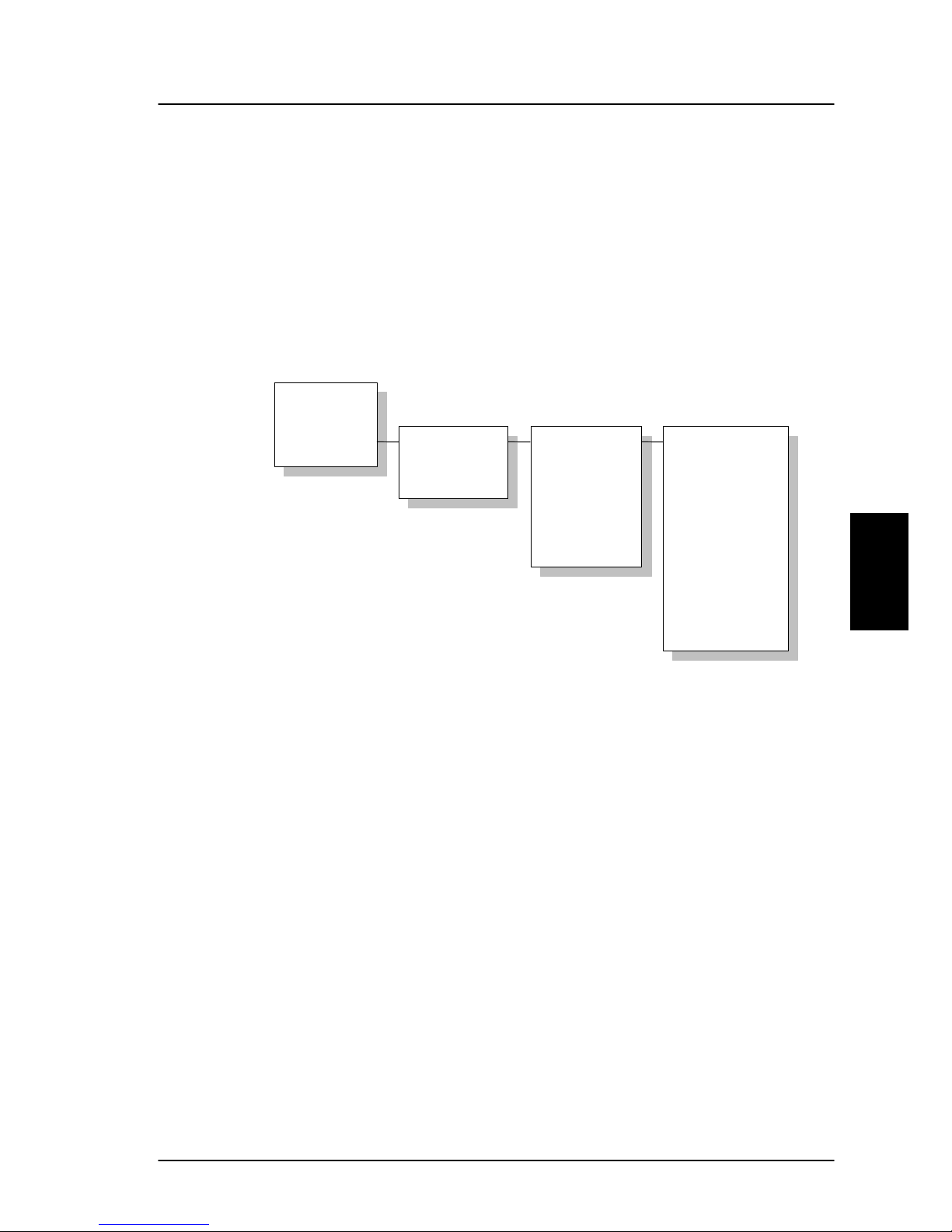
Menu System Operation
4
a RJ11 connector then select PABX mode. Use with
and
to toggle the values and to select.
Press to leave the sub menus.
4.3.25 LES Configuration
Please note:
The Distress LES functionality is available
on Fleet77 systems only.
This menu is used to select a list of LES operators. It
contains the following sub menus:
Default LES
PreferredLES
Reset LES
Distress LES
Mail Box
RJ11 Setup
LES Config
*W-Atlantic
E-Atlantic
Pacific
Indian
Spare 1
Spare 2
Spare 3
Spare 4
001: Comsat
002: BT
003: KDD
004: Teleno
r
005: OTE
006:
007:
008: FRAC
009: ST12
.
.
.
.
• Default LES
• PreferredLES
• Distress LES
The
Default LES list contains a list of those LES operators
which may be selected as gateway to the terrestrial
network. The last used LES will be marked with * and this
LES will also be the first LES tried next time the terminal is
May 2005 85

Operation Super User functions
4
logged on. If there's no LES list selected under Allowed or
Preferred LES, the Default LES list will contain the LES list
from the satellite bulletin board, meaning all available LES
in the selected Ocean region. Use
and to select
a Ocean region and then a LES.
You may also edit the LES names in the “Default LES” list.
Press
to start editing the selected name. You may
clear the name by pressing
.
An
Allowed LES list can be selected under the Service
User menu. If an Allowed LES list exist, only the LES's in
this list can be selected under Default and Preferred LES.
An Allowed LES list contains all available LES operators in
the selected ocean region. Those operators marked with *
can be used as Default LES operators and thus appears in
the Default LES list above. If all LES operators are allowed
and can be used there are no markings.
As there are many operators, you can use
PreferredLES
to make selections easier. The Preferred LES list can be
used to indicate in which order LES operators should
appear on the Default LES list. This is done by pressing
for each LES intended to be on the list and in the
order they should appear in the Default LES list. A prompt
for a TNID will appear in the handset display. This value is
usually 0, but in some countries with more than one
terrestrial network, the TNID can have another value. To
accept the default TNID, press
. Press again to
update the preferred LES list. To remove a LES from the
list, press
and then to update the list.
The
Reset LES command reset all the LES names to
default names.
The
Distress LES list contains a list of those LES operators
which may be selected as a LES when making a Distress
86 May 2005

Menu System Operation
4
Priority Call. Use and to select a Ocean region
and then a LES.
Note: If a Distress LES is not defined for each Ocean
Region, an alarm will appear and the entry ‘Distress
LES is not selected in all Ocean Regions’ will be
added to the alarm log.
4.3.26 Additional Features
The Additional Features contains two sub menus
STU
Setup
(Secure Telephone Unit ) and 128K Setup ). To
enable the STU or 128K services a PIN code must be
entered. The PIN code can be retrieved from your
distributor. Use
and to choose STU Setup or
128K Setup. If the PIN code is successfully entered a new
screen appears. Here the service can be enabled or
disabled. Use
to toggle and to change. Press
to leave the sub menu.
Mail Box
RJ11 Setup
LES Config
Add. Featur es
STU Setup
128K Setu
p
128 K PIN
_
STU PIN
_
STU
Disabled
128K Service
Disabled
May 2005 87

Operation Super User functions
4
4.3.27 Data Limits
The Data Limits menu enables the user to enter an upper
limit for the use of each high speed connection. This
feature is an effective way of preventing that a user by
mistake forgets to close a connection.
The Data Limits menu contains two sub menus
MPDS and
ISDN. Use to and to choose among them.
The
MPDS sub menu contains two parameters Limit and a
value for the maximum allowed amount of kilobytes that
can be transferred in each call.
Limit can be either ON or
OFF. If set to ON the MPDS connection will automatically
be closed down if the transferred data amount gets beyond
the entered maximum value. If set to
OFF, there will be no
limits for the amount of data that can be transferred. Use
to select Limit and to manipulate. To enter a
maximum limit press
. Then use the numeric buttons to
enter a value and press
to save. Press to leave the
sub menu.
The ISDN sub menu contains two parameters Limit and a
maximum duration for each call.
Limit can be either ON
or
OFF. If set to ON the call will automatically be closed
down if the call has lasted longer than the entered
maximum duration. If set to
OFF, there will be no
boundaries on the call duration. Use
to select Limit
and to mani pulate. To enter a maximum call duration
press
. Then use the numeric buttons to enter the
RJ11 Setup
LES Config
Add. Featur es
Data Limits
MPDS
ISDN
Limit OFF
00:00 hh:mm
Limit OFF
000000 Kb
88 May 2005

Menu System Operation
4
duration in hours and minutes and press to save. Press
to leave the sub menu.
4.3.28 Call Waiting Notification
The Call Waiting menu contains a number of sub menus.
Use
to and to choose among them. Press
to save the changes and press leave a menu. Please
refer to section 3.5.1 for general information about the Cal l
Waiting Notification.
The first menu item is
Support and it is used for enabling
or disabling the Call Waiting Notification service. A third
option “
Dial Spec.“ makes it possible to control the
Add.Features
Data Limits
Call Waiting
---------------
Support
Limit Calls
Handset
RJ11
Pend. Time
Caller #1-5
Disabled
Enabled
Dial Spec.
Notification
Ring Tone
Yes / No
Ring Tone 1-8
Notification
Ring Tone
RJ11 #1-3
Ring Type 1-8
Pend. Time
0030
Number
Ring Tones
Caller # No
Handset
RJ11
May 2005 89

Operation Super User functions
4
Support setting using the AT shell command
1
. Choose the
settings by pressing
and press leave the menu.
The second menu item is
Limit Calls. The user may not
want all calls to interrupt the MPDS sessions. It is possi ble
to enter up to five phone numbers that are allowed to
interrupt the MPDS sessions while all others will be
rejected. If
Limit Calls is set to “Enabled” only the five
phone numbers are allowed to interrupt. If
Limit Calls is
set to “
Disabled” all calls are allowed to interrupt. The
third option “
Dial Spec.“ makes it possible to control the
Limit Calls setting using the AT command
2
. Please note
that the
Limit Calls service is not supported by the LES at
present time. However, it will most likely be available in
near future. Choose the settings by pressing
and press
leave the menu.
The third menu item is
Handset and it contains two sub
items:
Notification and Ring Tone. Notification can be
either
Yes or No and it controls whether or not the 4-Wire
Handset should be used for Call Waiting Notification.
Ring
Tone
can be used for choosing among the 8 Ring Tones.
Choose the settings by pressing
and press leave
the menu.
The fourth menu item is
RJ11 and it contains two sub
items:
Notification and Ring Tone. Notification can be
1
If “Dial Spec.“ is chosen, support of Call Waiting Notification can
be controlled using the AT shell command “+WCWNS=<value>”
during the MPDS call setup. Possible values for the AT shell
command are: 0 =
DISABLED, 1 = ENABLED, 2 = AUTOMATIC.
2
If “Dial Spec.“ is chosen the Limit Calls setting can be
controlled using the AT command
2
“+WCWNR=<value> during the
MPDS call setup. Possible values are: 0 =
DISABLED, 1 =
ENABLED.
90 May 2005

Menu System Operation
4
either Yes or No for each of the three RJ11 2-wire
connectors. The item
Ring Tone can be used for choosing
a common 2-wire ring tone among eight ring tones. The
ring tones are described with the two symbols ‘#’ (sound)
and ‘ ‘ (no sound). Choose the settings by pressing
and press leave the menu.
The fifth menu item is Pending Time and this value is by
default set to 30 seconds. The Call Waiting Notification will
continue for a number of seconds corresponding to the
value of
Pending Time. If the user chooses to ignore the
notification for a longer period the incoming call will be
ignored. Enter a value and press
to save when leaving
the menu. Press to leave the menu without saving.
The last menu items are
Caller #1-5 and each of these
can contain a phone number that is allowed to interrupt the
MPDS sessions if this is enabled in the menu item
Limit
Calls
. Each number can be individually associated with a
ring tone and with the 4-Wire handset and/or a number of
the RJ11 2-Wire connectors. Configuration is done as
described in the menu items
Handset and RJ11.
May 2005 91

 Loading...