

Thrane&Thrane SAILOR 900 VSAT Installation & Service Manual
TRAINING, INSTALLATION & SERVICE MANUAL
SAILOR 900 VSAT System


SAILOR 900 VSAT
Training, installation and service manual
Document number: 98-133966-E2
Release date: 11 December 2012

Disclaimer
Any responsibility or liability for loss or damage in connection with the use of this product and the
accompanying documentation is disclaimed by Thrane & Thrane. The information in this manual is
provided for information purposes only, is subject to change without notice and may contain errors
or inaccuracies.
Manuals issued by Thrane & Thrane are periodically revised and updated. Anyone relying on this
information should acquire the most current version e.g. from http://www.thrane.com or from the
distributor. Thrane & Thrane is not responsible for the content or accuracy of any translations or
reproductions, in whole or in part, of this manual from any other source.
Copyright © 2012 Thrane & Thrane A/S. All rights reserved.
Trademark acknowledgements
• Thrane & Thrane is a registered trademark of Thrane & Thrane A/S in the European Union and the
United States.
• SAILOR is a registered trademark of Thrane & Thrane A/S in the European Union and the United
States.
• Windows is a registered trademark of Microsoft Corporation in the United States and other
countries.
• Other product and company names mentioned in this manual may be trademarks or trade names
of their respective owners.
GPL notification
The software included in this product contains copyrighted software that is licensed under the
GPL/LGPL. The verbatim licenses can be found online at:
http://www.gnu.org/licenses/old-licenses/gpl-2.0.html
http://www.gnu.org/licenses/old-licenses/lgpl-2.1.html
You may obtain the complete corresponding source code from us for a period of three years after
our last shipment of this product, which will be no earlier than 2021, by sending a money order or
check for DKK 50 to:
SW Technology/GPL Compliance,
Thrane & Thrane A/S,
Lundtoftegaardsvej 93D
2800 Lyngby
DENMARK
Please write "source for product SAILOR 900 VSAT" in the memo line of your payment. You may also
find a copy of the source at http://www.thrane.com/foss. This offer is valid to anyone in receipt of
this information.
ii 98-133966-E2

Safety summary
The following general safety precautions must be observed during all phases of operation,
service and repair of this equipment. Failure to comply with these precautions or with
specific warnings elsewhere in this manual violates safety standards of design,
manufacture and intended use of the equipment. Thrane & Thrane A/S assumes no liability
for the customer's failure to comply with these requirements.
Microwave radiation hazards
During transmission the Above Deck Unit (antenna) in
this system radiates Microwave Power.This radiation
may be hazardous to humans close to the Above Deck
Unit. During transmission, make sure that nobody gets
closer than the recommended minimum safety distance.
The minimum safety distance to the Above Deck Unit
reflector on the focal line is 30 m, based on a radiation
level of 10 W/m
Refer to the drawing below.
2
. No hazard exists >25° below the Above Deck Unit’s mounting plane.
MICROWAVE RADIATION
No personnel within safety distance
Safety distance:
30 m, 10 W/m
2
No-transmit zones
In order to protect personnel no-transmit zones can be programmed. For further
information see Blocking zones — azimuth and elevation on page 3-5.
Distance to other equipment
Do not move the Above Deck Unit closer to radars than the minimum safe distance
specified in section Interference on page 3-13 — it may cause damage to the Above Deck
Unit.
98-133966-E2 iii

Compass Safe Distance:
SAILOR 900 VSAT antenna or ADU (Above Deck Unit): min. 130 cm (IEC 945).
SAILOR 900 VSAT ACU (Antenna Control Unit): min. 10 cm (IEC 945)
Service
User access to the interior of the ACU is prohibited. Only a technician authorized by Thrane
& Thrane A/S may perform service - failure to comply with this rule will void the warranty.
Access to the interior of the Above Deck Unit is allowed. Replacement of certain modules as described in Service & maintenance on page 9-1 and general service may only be
performed by a technician authorized by Thrane & Thrane A/S.
Do not service or adjust alone
Do not attempt internal service or adjustments unless another person, capable of
rendering first aid resuscitation, is present.
Grounding, cables and connections
To minimize shock hazard and to protect against lightning, the equipment chassis and
cabinet must be connected to an electrical ground. The ACU must be grounded to the ship.
For further grounding information refer to the Installation manual.
Do not extend the cables beyond the lengths specified for the equipment. The cable
between the ACU and Above Deck Unit can be extended if it complies with the specified
data concerning cable losses etc.
Rx and Tx cables for the SAILOR 900 VSAT system are shielded and should not be affected
by magnetic fields. However, try to avoid running cables parallel to high power and AC/RF
wiring as it might cause malfunction of the equipment.
Power supply
The voltage range for the SAILOR 900 VSAT is 20 — 32 VDC. Note that the Above Deck Unit
is powered by the ACU.
If a 24 VDC power bus is not available, an external 115/230 VAC to 28 VDC power supply can
be used, for example a SAILOR 6080 Power Supply.
Do not operate in an explosive atmosphere
Do not operate the equipment in the presence of flammable gases or fumes. Operation of
any electrical equipment in such an environment constitutes a definite safety hazard.
Keep away from live circuits
Operating personnel must not remove equipment covers. Component replacement and
internal adjustment must be made by qualified maintenance personnel. Do not replace
components with the power cable connected. Under certain conditions, dangerous
voltages may exist even with the power cable removed. To avoid injuries, always
disconnect power and discharge circuits before touching them.
Failure to comply with the rules above will void the warranty!
iv 98-133966-E2
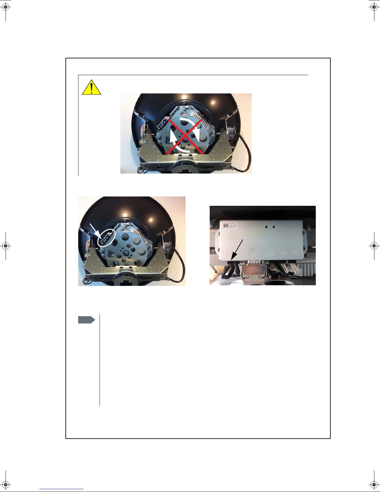
CAUTION! Do not manually turn the Polarisation Unit of the antenna, it
may cause damage to the antenna.
If needed to turn the Polarisation Unit manually, remove the connector (1) marked M of the
Polarisation Motor Module (2).
(1)
(2)
Remove
M
VSAT restrictions
Note
There are restrictions in use of the frequency band 13.75 to 14 GHz in the
following countries:
• Belgium
• Hungary
• Latvia
• Malta
• Slovakia
Contact VSAT modem provider for local setups.
98-133966-E2 v

vi 98-133966-E2

Table of contents
Chapter 1 About this manual
1.1 Intended readers ................................................................................1-1
1.2 Manual overview ...............................................................................1-1
1.3 Software version ............................................................................... 1-2
1.4 Related documents ............................................................................ 1-2
1.5 Typography ....................................................................................... 1-2
1.6 Precautions ....................................................................................... 1-3
Chapter 2 Introduction
2.1 SAILOR 900 VSAT system .................................................................. 2-1
2.1.1 Overview ......................................................................................... 2-1
2.1.2 Above Deck Unit (ADU) ....................................................................2-4
2.1.3 Antenna Control Unit (ACU) .............................................................2-8
2.1.4 VSAT Modem Unit (VMU) .............................................................. 2-10
2.1.5 Satellite type approvals ................................................................. 2-10
2.1.6 Power supply (optional) ................................................................ 2-10
2.1.7 Service activation .......................................................................... 2-10
2.2 Part numbers and options ................................................................ 2-11
2.2.1 Applicable Thrane & Thrane model and part numbers .................... 2-11
2.2.2 Options for SAILOR 900 VSAT ......................................................... 2-11
98-133966-E2 vii

Table of contents
Chapter 3 Installation
3.1 Unpacking .........................................................................................3-1
3.1.1 What’s in the box .............................................................................3-1
3.1.2 Initial inspection ............................................................................. 3-2
3.1.3 Tools needed ..................................................................................3-3
3.2 Site preparation ................................................................................ 3-3
3.2.1 General site considerations ............................................................. 3-3
3.2.2 Obstructions (ADU shadowing) .......................................................3-4
3.2.3 Blocking zones — azimuth and elevation .........................................3-5
3.2.4 Safe access to the ADU: Radiation hazard ....................................... 3-6
3.2.5 Ship motion and offset from the ship’s motion centre ..................... 3-7
3.2.6 ADU mast design: Foundation and height .......................................3-8
3.2.7 Interference ...................................................................................3-13
3.2.8 Other precautions .......................................................................... 3-17
3.3 Installation of the ADU .....................................................................3-18
3.3.1 Installing the ADU ..........................................................................3-19
3.3.2 Opening and removing the service hatch ...................................... 3-22
3.3.3 Grounding the ADU ....................................................................... 3-23
3.3.4 Alternative ADU cable ................................................................... 3-25
3.4 Installation of the ACU (bulkhead) ................................................... 3-26
3.4.1 Installing the ACU (bulkhead) .......................................................3-26
3.4.2 Grounding the ACU (bulkhead) ..................................................... 3-27
3.4.3 SAILOR 900 VSAT ACU (bulkhead) with cable support ................... 3-28
3.5 Installation of the 19” rack version of the ACU ................................ 3-30
3.5.1 Installing the 19” rack version of the ACU ...................................... 3-30
3.5.2 Grounding the 19” rack version of the ACU .....................................3-31
3.6 Installation of the VMU ................................................................... 3-32
3.6.1 General mounting considerations — VMU ..................................... 3-32
3.7 Installing the dual-antenna mode (optional) ................................... 3-33
viii 98-133966-E2

Chapter 4 Interfaces
4.1 Interfaces of the SAILOR 900 VSAT ACU ............................................ 4-1
4.1.1 ACU bulkhead — LEDs, display and keypad ...................................... 4-1
4.1.2 ACU 19” rack version — LEDs, display and keypad ............................ 4-1
4.1.3 ACU bulkhead — Connector panel — overview ..................................4-2
4.1.4 ACU 19” rack version — Connector panel — overview ........................4-2
4.1.5 DC Input connector ..........................................................................4-3
4.1.6 ADU connector ................................................................................4-4
4.1.7 Rx/Tx connectors for VMU ..........................................................4-4
4.1.8 NMEA 0183 connector (RS-422) .......................................................4-5
4.1.9 RS-232 and RS-422 connectors .......................................................4-6
4.1.10 LAN1, LAN2, LAN3 and LAN4 connectors ..........................................4-7
4.2 Interfaces of the VMU .......................................................................4-9
4.2.1 Connecting an iNFINITI® Series Satellite Router .............................4-9
4.2.2 Connecting an Evolution® Satellite Router ................................... 4-10
4.2.3 Connecting a Comtech 570 L or 625 Satellite Modem .................... 4-10
4.2.4 Connecting a Satlink2900 VSAT modem ......................................... 4-11
4.2.5 Connecting a Gilat SkyEdge II VSAT modem .................................. 4-12
Table of contents
Chapter 5 Connecting power
5.1 Power source .................................................................................... 5-1
5.2 Power cable selection .......................................................................5-2
5.2.1 Source impedance ...........................................................................5-2
5.2.2 Measuring the ship source impedance ............................................5-2
5.2.3 Power cable recommendations .......................................................5-3
5.3 Connecting power .............................................................................5-4
5.4 Power up ..........................................................................................5-5
Chapter 6 Configuration
6.1 Introduction to the built-in web interface ......................................... 6-1
6.1.1 Overview ......................................................................................... 6-1
6.1.2 Connecting to the web interface ......................................................6-2
98-133966-E2 ix

Table of contents
6.2 Calibration of the SAILOR 900 VSAT .................................................. 6-4
6.2.1 Preparing for calibration ................................................................. 6-4
6.2.2 Heading and calibration of azimuth and cable ................................6-6
6.2.3 Flow chart for azimuth and cable calibration .................................6-10
6.2.4 Line up procedure .......................................................................... 6-11
6.2.5 SAILOR 900 VSAT fixed TX gain principle .......................................6-13
6.3 Configuration with the web interface ..............................................6-14
6.3.1 Overview and navigation ................................................................6-14
6.3.2 Using the Dashboard .....................................................................6-18
6.3.3 Satellite profiles and VSAT modem profiles ....................................6-21
6.3.4 Setting up Blocking zones (RX and TX) ......................................... 6-27
6.3.5 Configuring the LAN network ........................................................ 6-29
6.3.6 E-mail setup .................................................................................6-32
6.3.7 Sending statistics reports .............................................................. 6-33
6.3.8 Sending a diagnostics report ........................................................6-36
6.3.9 Dual antenna mode (optional) ...................................................... 6-37
6.3.10 Upload .......................................................................................... 6-42
6.3.11 Administration .............................................................................. 6-43
6.4 Keypad and menus of the ACU ........................................................ 6-49
6.4.1 ACU display and keypad ...............................................................6-49
6.4.2 Navigating the menus ................................................................... 6-50
6.4.3 The menu tree ...............................................................................6-51
6.4.4 Adjusting brightness of the display ............................................... 6-54
6.4.5 Resetting the system ..................................................................... 6-55
6.5 SNMP support ................................................................................. 6-55
Chapter 7 Installation check
7.1 Installation check list: Antenna ..........................................................7-1
7.2 Installation check list: ACU, connectors and wiring ........................... 7-3
7.3 Installation check list: Functional test in harbor ................................ 7-5
Chapter 8 Daily use — Quick guide
Chapter 9 Service & maintenance
9.1 Getting support: Helpdesk ................................................................9-2
9.1.1 Help desk and diagnostic report .....................................................9-2
x 98-133966-E2

Table of contents
9.2 Software update .............................................................................. 9-5
9.2.1 Hardware and software requirements ............................................ 9-5
9.2.2 Software update (ADU and ACU) .................................................... 9-5
9.2.3 Verifying the software update ......................................................... 9-6
9.3 Status signalling with LEDs and status messages ............................. 9-8
9.3.1 Overview ........................................................................................ 9-8
9.3.2 LEDs of the ADU modules ............................................................... 9-9
9.3.3 LEDs in the ACU ............................................................................ 9-10
9.4 Removal and replacement of the ACU ............................................... 9-11
9.5 Removal and replacement of ADU modules ..................................... 9-12
9.5.1 Overview ....................................................................................... 9-12
9.5.2 Replacing the GPS module ............................................................ 9-18
9.5.3 Replacing the VSAT Interface Module (VIM) .................................. 9-21
9.5.4 Replacing the DC-Motor Driver Module (DDM) ..............................9-24
9.5.5 Replacing the Polarisation Motor Module (PMM) ..........................9-28
9.5.6 Replacing the Pedestal Control Module (PCM) ..............................9-32
9.5.7 Replacing motor and encoder .......................................................9-34
9.5.8 Replacing the Drive Belts ..............................................................9-55
9.5.9 Replacing the Zero Reference Module (ZRM) ................................9-63
9.5.10 Replacing the Inertial Sensor Module (ISM) ..................................9-70
9.5.11 Replacing the Polarisation Unit .....................................................9-73
9.5.12 Replacing the BUC Fan .................................................................. 9-77
9.5.13 Replacing the Block Up Converter (BUC) .......................................9-78
9.5.14 Replacing the Low Noise Block down converter (LNB) .................. 9-80
9.5.15 Replacing the Ortho Mode Transducer (OMT) ................................9-82
9.5.16 Replacing the rotary joint ..............................................................9-85
9.6 Updating VIM/PCM calibration data ................................................9-89
9.7 Troubleshooting .............................................................................. 9-91
9.7.1 Overview ....................................................................................... 9-91
9.7.2 Event list for troubleshooting ........................................................ 9-91
9.7.3 Diagnostic report for troubleshooting ............................................ 9-91
9.7.4 Troubleshooting — BUC .................................................................9-92
9.7.5 Troubleshooting — LNB .................................................................9-93
9.7.6 System block diagram (ADU) .........................................................9-93
98-133966-E2 xi

Table of contents
Appendix A Technical specifications
A.1 SAILOR 900 VSAT system components .............................................. A-1
A.1.1 General specifications ..................................................................... A-1
A.1.2 ADU ................................................................................................A-2
A.1.3 ACU ................................................................................................A-4
A.1.4 Supported VSAT modems ................................................................A-5
A.2 Outline drawings ..............................................................................A-6
A.2.1 ADU ................................................................................................A-6
A.2.2 ACU, bulkhead ................................................................................A-7
A.2.3 ACU, 19 inch rack ........................................................................... A-8
A.2.4 N-connector interface on the ADU ..................................................A-9
A.3 VSAT LNB Data Sheet (physical LNB) ............................................... A-10
A.3.1 VSAT LNB user installation and configuration information ............ A-10
A.4 VSAT 8 W BUC Data Sheet (Extended) ............................................. A-12
Appendix B VMU cable specifications
B.1 Modem Cable Comtech Serial & RSSI TT7016A ..................................B-2
B.2 Modem Cable iNIFINITI iDirect VSAT modem ....................................B-3
Appendix C VMU settings requirements
C.1 Open AMIP setup for iDirect INFINITI & Evolution ............................. C-2
C.1.1 Protocol and interfaces ...................................................................C-2
C.1.2 Sample options file ......................................................................... C-5
C.1.3 Configuration examples (OpenAMIP) ..............................................C-8
C.2 Non-Open-AMIP setup for iDirect iNFINITI 5000 & Evolution X5 .......C-9
C.2.1 Protocol and interfaces ................................................................... C-9
C.2.2 Console port settings .....................................................................C-10
C.2.3 Configuration examples (Non-OpenAMIP) .....................................C-12
C.3 Comtech 570L, ROSS box & ACU .......................................................C-14
C.3.1 Protocols and interfaces .................................................................C-14
C.4 STM SatLink 2900 VSAT modem .......................................................C-15
C.4.1 Interfaces and VSAT modem configuration .....................................C-15
C.4.2 ACU configuration ..........................................................................C-16
xii 98-133966-E2

C.5 Gilat SkyEdge II VSAT modem ......................................................... C-17
C.5.1 Interfaces and VSAT modem configuration .................................... C-17
C.5.2 ACU configuration ......................................................................... C-18
Appendix D Command line interface
D.1 Introduction ......................................................................................D-1
D.1.1 Telnet connection ........................................................................... D-2
D.1.2 Help ............................................................................................... D-2
D.1.3 Conventions ................................................................................... D-3
D.2 Supported commands ...................................................................... D-4
D.2.1 config ............................................................................................. D-4
D.2.2 demo ............................................................................................. D-4
D.2.3 dual_antenna ................................................................................. D-5
D.2.4 exit ................................................................................................. D-5
D.2.5 help ............................................................................................... D-5
D.2.6 modem ........................................................................................... D-6
D.2.7 satellite .......................................................................................... D-6
D.2.8 status ............................................................................................. D-9
D.2.9 system ............................................................................................ D-9
D.2.10 track ..............................................................................................D-10
D.2.11 zone ...............................................................................................D-11
Table of contents
Appendix E DVB-S satellites
Appendix F Grounding and RF protection
F.1 Why is grounding required? .............................................................. F-1
F.1.1 Reasons for grounding .................................................................... F-1
F.1.2 Safety .............................................................................................. F-1
F.1.3 ESD Protection ................................................................................ F-1
F.2 Grounding Recommendations ...........................................................F-2
F.2.1 Grounding the ACU .........................................................................F-2
F.2.2 Grounding the ADU .........................................................................F-3
F.3 Alternative grounding for steel hulls .................................................F-5
F.3.1 Grounding the ACU .........................................................................F-5
F.3.2 Grounding the ADU .........................................................................F-5
98-133966-E2 xiii

Table of contents
F.4 Alternative grounding for aluminum hulls ........................................ F-7
F.4.1 Grounding the ACU ......................................................................... F-7
F.4.2 Grounding the ADU ......................................................................... F-7
F.5 Alternative grounding for fibre glass hulls ....................................... F-9
F.5.1 Grounding the ACU ......................................................................... F-9
F.5.2 Grounding the ADU ........................................................................F-10
F.6 Separate ground cable ..................................................................... F-11
F.6.1 Ground cable - construction .......................................................... F-11
F.6.2 Ground cable - connection ............................................................. F-12
F.6.3 Isolation of the ADU from the mounting base ................................. F-12
F.7 Jumper cable for grounding .............................................................F-14
F.8 RF interference ................................................................................F-15
F.8.1 Recommendations .........................................................................F-15
Appendix G System messages
G.1 Event messages — overview ............................................................. G-1
G.2 List of ADU events .............................................................................G-2
G.3 List of ACU events ............................................................................ G-9
Appendix H Approvals
H.1 Satellite approvals ............................................................................ H-1
H.2 CE (R&TTE) ........................................................................................ H-1
Glossary ............................................................................................................ Glossary-1
Index .................................................................................................................Index-1
xiv 98-133966-E2

List of figures
Chapter 1 About this manual
Chapter 2 Introduction
Figure 2-1: Above Deck Unit and Antenna Control Unit (ACU).................................................2-2
Figure 2-2: Above Deck Unit and Antenna Control Unit (ACU), 19” rack version ......................2-2
Figure 2-3: Above Deck Unit (ADU).........................................................................................2-4
Figure 2-4: Above Deck Unit modules 1/2............................................................................... 2-5
Figure 2-5: Above Deck Unit modules 2/2 .............................................................................. 2-6
Figure 2-6: SAILOR 900 VSAT ACU, connector overview ......................................................... 2-8
Figure 2-7: SAILOR 900 VSAT ACU, 19” rack version............................................................... 2-9
Figure 2-8: Antenna Control Unit for bulkhead installation.................................................... 2-9
Figure 2-9: Antenna Control Unit for 19” rack installation ...................................................... 2-9
Chapter 3 Installation
Figure 3-1: Signal degradation because of obstructing objects ...............................................3-4
Figure 3-2: 2 blocking zones with no-transmit zones, azimuth (example) .............................. 3-5
Figure 3-3: Blocking zone with no-transmit zones, elevation angle (example)....................... 3-5
Figure 3-4: Radiation hazard, safety distance 30 m ............................................................... 3-6
Figure 3-5: Maximum distance from the ship’s motion centre (h max)....................................3-7
Figure 3-6: ADU mast flange, top and side view..................................................................... 3-8
Figure 3-7: ADU mast flange, recommended flatness on the mast mount plateau.................. 3-8
Figure 3-8: ADU mast flange, distance to the welded seam ................................................... 3-9
Figure 3-9: ADU, bottom view................................................................................................ 3-9
Figure 3-10: Free mast length and bracing for a tall mast ...................................................... 3-10
Figure 3-11: Interference with the vessel’s radar.................................................................... 3-14
Figure 3-12: Recommended distance to transmitters (m) for frequencies below 1000 MHz ..... 3-16
Figure 3-13: Drain pipe with free space.................................................................................. 3-17
Figure 3-14: Use of strong sling with a belt and tag lines for safe hoisting ............................. 3-18
Figure 3-15: Free space for access to the service hatch........................................................... 3-19
Figure 3-16: ADU installation, webbed sling attached to the 4 lifting brackets........................3-20
Figure 3-17: Mounting the ADU on the mast flange................................................................3-20
Figure 3-18: Connecting the ADU cable .................................................................................. 3-21
Figure 3-19: Opening the service hatch ..................................................................................3-22
Figure 3-20: Removing the 2 split pins ...................................................................................3-22
Figure 3-21: Removing the service hatch ................................................................................3-23
98-133966-E2 xv

List of figures
Figure 3-22: ADU, bolt for optimum grounding ......................................................................3-24
Figure 3-23: SAILOR 900 VSAT ACU without cable support .....................................................3-26
Figure 3-24: ACU, connector panel......................................................................................... 3-26
Figure 3-25: SAILOR 900 VSAT ACU, bulkhead version, ground stud ...................................... 3-27
Figure 3-26: Cable relief for the ACU...................................................................................... 3-28
Figure 3-27: Mounting the cable relief 1/2.............................................................................. 3-28
Figure 3-28: Mounting the cable relief 2/2 .............................................................................3-29
Figure 3-29: ACU, 19” rack version, On/off switch at the back................................................. 3-30
Figure 3-30: ACU, LAN connector at the front: Service port......................................................3-31
Figure 3-31: ACU, 19” rack version, ground stud .....................................................................3-31
Figure 3-32: Dual mode antenna, overview ............................................................................3-33
Figure 3-33: Dual mode antenna, connecting cables (example) ............................................. 3-34
Chapter 4 Interfaces
Figure 4-1: ACU bulkhead, LEDs, display and keypad ..............................................................4-1
Figure 4-2: ACU rack version, LEDs, display and keypad..........................................................4-1
Figure 4-3: ACU bulkhead, connector panel overview............................................................. 4-2
Figure 4-4: ACU rack version, connector panel overview ........................................................4-2
Figure 4-5: DC Input connector with power cable ...................................................................4-3
Figure 4-6: LAN1 —LAN4 connectors ....................................................................................... 4-7
Figure 4-7: Connecting an iNFINITI® Series Satellite Router ..................................................4-9
Figure 4-8: Connecting an Evolution Satellite Router ............................................................4-10
Figure 4-9: Connecting a Comtech 570 L or 625 Satellite Modem ..........................................4-10
Figure 4-10: Connecting a SatLink 2900 Modem ..................................................................... 4-11
Figure 4-11: Connecting a Gilat SkyEdge II VSAT Modem ........................................................4-12
Chapter 5 Connecting power
Figure 5-1: Measuring the ship source impedance.................................................................5-3
Figure 5-2: Connecting power to DC Input..............................................................................5-4
Figure 5-3: ACU display after first power on (example with LAN ports 1 and 4 used)...............5-5
Chapter 6 Configuration
Figure 6-1: Configuration setup.............................................................................................. 6-1
Figure 6-2: LAN connector used for configuring the SAILOR 900 VSAT ...................................6-2
Figure 6-3: SAILOR 900 VSAT Dashboard ...............................................................................6-3
Figure 6-4: Service profile for calibration ...............................................................................6-5
Figure 6-5: Web interface: SERVICE, Calibration.....................................................................6-6
xvi 98-133966-E2

List of figures
Figure 6-6: Example for azimuth and cable calibration — step by step ..................................6-10
Figure 6-7: Web interface: SERVICE, Line up: Ready for activation .........................................6-11
Figure 6-8: Web interface: SERVICE, Line up: Antenna ready................................................ 6-12
Figure 6-9: Fixed TX gain principle....................................................................................... 6-13
Figure 6-10: Topics in the web interface (SITE MAP)............................................................... 6-14
Figure 6-11: Sections of the web interface.............................................................................. 6-15
Figure 6-12: Web interface: DASHBOARD ............................................................................... 6-18
Figure 6-13: Web interface: SETTINGS - list of satellite profiles (example) .............................. 6-21
Figure 6-14: Web interface: SETTINGS, Satellite profiles — new entry (example) .....................6-22
Figure 6-15: Web interface: SETTINGS, VSAT modem profiles — list (example)........................6-24
Figure 6-16: Web interface: SETTINGS, VSAT modem profiles — new entry (example) .............6-25
Figure 6-17: Supported VSAT modems in software version 1.30 ..............................................6-25
Figure 6-18: Satellite profile for generic modem.....................................................................6-26
Figure 6-19: Web interface: SETTINGS, Blocking zones — azimuth and elevation....................6-27
Figure 6-20: Blocking zone, example: 315 - 45 degrees ..........................................................6-28
Figure 6-21: Blocking zone, example: 45 - 315 degrees ..........................................................6-28
Figure 6-22: Web interface: SETTINGS, Network (default settings) ..........................................6-29
Figure 6-23: Web interface: SETTINGS, E-mail setup (example) ..............................................6-32
Figure 6-24: Web interface: SETTINGS, Reports (example)......................................................6-33
Figure 6-25: Statistics — how to read data for a range ............................................................6-35
Figure 6-26: Statistics report (example) ..................................................................................6-36
Figure 6-27: Dual-antenna mode, link on DASHBOARD..........................................................6-37
Figure 6-28: Enabling dual-antenna mode in Master ACU ......................................................6-38
Figure 6-29: Dual-antenna mode, add Slave modem profile...................................................6-39
Figure 6-30: Dual-antenna mode, add Slave satellite profile ................................................. 6-40
Figure 6-31: Dual-antenna mode, Activate ............................................................................ 6-40
Figure 6-32: Dual-antenna mode, blocking zones — azimuth and elevation............................ 6-41
Figure 6-33: Dual-antenna mode, line up...............................................................................6-42
Figure 6-34: Web interface: Administration ............................................................................6-43
Figure 6-35: Web interface: Administration, change administrator logon and password.........6-44
Figure 6-36: Web interface: ADMINISTRATION, Reset administrator password .......................6-44
Figure 6-37: Web interface: ADMINISTRATION, User permissions...........................................6-45
Figure 6-38: Web interface: Administration, Export/import configuration ...............................6-46
Figure 6-39: Web interface: ADMINISTRATION, Factory default ..............................................6-48
Figure 6-40: Display (example) and keypad of the ACU...........................................................6-49
Figure 6-41: Antenna Control Unit, menu tree........................................................................ 6-51
Figure 6-42: Reset the system................................................................................................ 6-55
98-133966-E2 xvii

List of figures
Chapter 7 Installation check
Chapter 8 Daily use — Quick guide
Figure 8-1: SAILOR 900 VSAT Quick Guide — web interface and satellite profiles.................... 8-1
Figure 8-2: SAILOR 900 VSAT Quick Guide — Viewing system parameters...............................8-2
Chapter 9 Service & maintenance
Figure 9-1: Web interface: HELPDESK.....................................................................................9-2
Figure 9-2: Web interface: HELPDESK, Event list.....................................................................9-3
Figure 9-3: LAN connector used for configuring the SAILOR 900 VSAT ...................................9-5
Figure 9-4: Verifying software update ....................................................................................9-7
Figure 9-5: LEDs on the ACU ................................................................................................ 9-10
Figure 9-6: LEDs on the ACU, 19” rack version...................................................................... 9-10
Figure 9-7: Removal and replacement of the ACU bulkhead .................................................. 9-11
Figure 9-8: Removal and replacement of the ACU 19” rack.................................................... 9-11
Figure 9-9: ADU modules and motor stop switch...................................................................9-12
Figure 9-10: Service switch .....................................................................................................9-16
Figure 9-11: Above Deck Unit modules (continued).................................................................9-17
Figure 9-12: GPS module ........................................................................................................9-18
Figure 9-13: Switch off the power to the antenna....................................................................9-19
Figure 9-14: GPS module facing the service hatch...................................................................9-19
Figure 9-15: Connector for GPS PCB....................................................................................... 9-20
Figure 9-16: Screws on GPS module.......................................................................................9-20
Figure 9-17: VSAT Interface Module (VIM) ..............................................................................9-21
Figure 9-18: Location of the VIM .............................................................................................9-21
Figure 9-19: Replacing the VIM — remove 2 F-connectors...................................................... 9-22
Figure 9-20: Replacing the VIM — remove 2 N, 2 F, 1 SMA and 1 SUB-D connectors ................9-22
Figure 9-21: Replacing the VIM — remove 4 Allen screws....................................................... 9-23
Figure 9-22: DC-Motor Driver Module (DDM) for Cross Elevation............................................ 9-24
Figure 9-23: Location of the Cross Elevation DDM ..................................................................9-25
Figure 9-24: Replacing the DDM — remove connectors.......................................................... 9-25
Figure 9-25: Location of the Elevation DDM............................................................................9-26
Figure 9-26: Elevation DDM, connectors.................................................................................9-26
Figure 9-27: location of the Azimuth DDM.............................................................................. 9-27
Figure 9-28: Azimuth DDM, connectors ..................................................................................9-28
Figure 9-29: Polarisation Motor Module, remove connectors .................................................9-29
Figure 9-30: Polarisation Motor Module, remove screws........................................................ 9-30
xviii 98-133966-E2

List of figures
Figure 9-31: Polarisation Motor Module, inserting ................................................................. 9-31
Figure 9-32: Location of the PCM............................................................................................9-32
Figure 9-33: Removing the PCM — connectors .......................................................................9-33
Figure 9-34: Motors and encoders..........................................................................................9-34
Figure 9-35: Location of the Elevation Motor & Encoder .........................................................9-35
Figure 9-36: Elevation motor and encoder, loosen the belt tensioner .....................................9-35
Figure 9-37: Elevation Motor and Encoder, adjust belt tension ...............................................9-36
Figure 9-38: Elevation DDM, disconnect 2 connectors.............................................................9-36
Figure 9-39: Elevation motor and encoder, loosen the screws for the motor assembly............9-37
Figure 9-40: Elevation motor and encoder, tighten the screws for the motor assembly .......... 9-38
Figure 9-41: Elevation motor and encoder, adjust belt tension .............................................. 9-38
Figure 9-42: Elevation motor and encoder, check of belt tension............................................9-39
Figure 9-43: Elevation motor and encoder, loosen the belt tensioner .....................................9-39
Figure 9-44: Azimuth motor, remove cover ............................................................................. 9-41
Figure 9-45: Azimuth motor, loosen the belt tensioner ........................................................... 9-41
Figure 9-46: Azimuth motor, adjust belt tension.....................................................................9-42
Figure 9-47: Azimuth DDM, disconnect connector ..................................................................9-42
Figure 9-48: Azimuth motor, loosen the screws for the motor assembly .................................9-43
Figure 9-49: Azimuth motor, tighten the screws for the motor assembly.................................9-44
Figure 9-50: Azimuth motor, adjust belt tension.....................................................................9-44
Figure 9-51: Azimuth motor, tighten the belt tensioner ..........................................................9-45
Figure 9-52: Azimuth encoder, remove cover..........................................................................9-46
Figure 9-53: Azimuth DDM, disconnect connector ..................................................................9-46
Figure 9-54: Azimuth encoder, remove...................................................................................9-47
Figure 9-55: Azimuth encoder, adjust belt tension..................................................................9-47
Figure 9-56: Azimuth Encoder, adjust belt tension ................................................................ 9-48
Figure 9-57: Azimuth motor, tighten the belt tensioner ......................................................... 9-48
Figure 9-58: Replacement of X-Elevation Motor & Encoder 1 .................................................9-49
Figure 9-59: X-Elevation Motor & Encoder — belt tension/adjustment screw ......................... 9-50
Figure 9-60: Cross Elevation motor assembly, 4 Allen screws ................................................ 9-50
Figure 9-61: Cross Elevation motor assembly, do not tighten screws ...................................... 9-51
Figure 9-62: X-Elevation Motor & Encoder — adjust belt tension ............................................ 9-51
Figure 9-63: Belt tension in 3 positions ..................................................................................9-52
Figure 9-64: Cross Elevation motor assembly, tighten screws .................................................9-52
Figure 9-65: Polarisation Motor, disconnecting power............................................................9-53
Figure 9-66: Polarisation Motor, removing 4x4 mm Allen screws............................................9-53
Figure 9-67: Removing the sub-D connector of the PMM........................................................9-54
98-133966-E2 xix

List of figures
Figure 9-68: Polarisation Encoder, removing ......................................................................... 9-54
Figure 9-69: Location of the X Elevation Drive Belt .................................................................9-55
Figure 9-70: Removing the cable drum ..................................................................................9-56
Figure 9-71: Location of the Elevation Drive Belt ....................................................................9-57
Figure 9-72: Elevation Drive Belt............................................................................................ 9-57
Figure 9-73: Elevation motor and encoder, loosen the belt tensioner .....................................9-58
Figure 9-74: Elevation motor and encoder, adjust belt tension...............................................9-58
Figure 9-75: Elevation Drive Belt............................................................................................ 9-59
Figure 9-76: Azimuth drive modules, remove cover................................................................9-60
Figure 9-77: Azimuth drive belt, loosen the belt tensioner ......................................................9-61
Figure 9-78: Azimuth drive belt, adjust belt tension ................................................................9-61
Figure 9-79: Getting access to the azimuth drive wheel.......................................................... 9-62
Figure 9-80: Azimuth Drive Belt .............................................................................................9-62
Figure 9-81: Zero Reference Modules (ZRM), location ...........................................................9-63
Figure 9-82: Zero Reference Module (ZRM) ...........................................................................9-63
Figure 9-83: X Elevation ZRM, disconnect connector.............................................................. 9-65
Figure 9-84: X Elevation ZRM, slide out .................................................................................9-65
Figure 9-85: Elevation ZRM, disconnect connector .................................................................9-66
Figure 9-86: Elevation ZRM, remove screws ...........................................................................9-67
Figure 9-87: Azimuth ZRM, remove cover...............................................................................9-68
Figure 9-88: Azimuth ZRM, disconnect connector ..................................................................9-68
Figure 9-89: Azimuth ZRM, disconnect connector ..................................................................9-69
Figure 9-90: Polarisation ZRM, disconnecting........................................................................ 9-69
Figure 9-91: Polarisation ZRM, loosen 2x4 mm Allen screws.................................................. 9-70
Figure 9-92: Inertial Sensor Module (ISM), location............................................................... 9-70
Figure 9-93: Inertial Sensor Module (ISM) ..............................................................................9-71
Figure 9-94: Removing the ISM.............................................................................................. 9-72
Figure 9-95: Removing the ISM Sub D connectors ..................................................................9-72
Figure 9-96: Removing the sub-D connector of the PMM ....................................................... 9-74
Figure 9-97: Disconnecting the LNBs...................................................................................... 9-75
Figure 9-98: Removing the cable spool ..................................................................................9-75
Figure 9-99: Disconnecting the OMT connector ......................................................................9-76
Figure 9-100: Disconnecting the OMT connector ...................................................................... 9-76
Figure 9-101: Removing the BUC fan ....................................................................................... 9-77
Figure 9-102: Block Up Converter (BUC), location ....................................................................9-78
Figure 9-103: Block Up Converter (BUC)................................................................................... 9-78
Figure 9-104: BUC, removing ...................................................................................................9-79
xx 98-133966-E2

List of figures
Figure 9-105: BUC, removing (continued).................................................................................9-79
Figure 9-106: Low Noise Block (LNB)....................................................................................... 9-80
Figure 9-107: LNB, removing.................................................................................................... 9-81
Figure 9-108: LNB, removing (continued) ................................................................................. 9-81
Figure 9-109: Ortho Mode Transducer (OMT)........................................................................... 9-82
Figure 9-110: OMT, removing 2xTorx20 screws on top............................................................. 9-83
Figure 9-111: OMT, removing 4xTorx20 screws on the left-hand rail of the Polarisation Unit... 9-83
Figure 9-112: OMT, removing 4xTorx20 screws on the right-hand rail of the Polarisation Unit 9-84
Figure 9-113: OMT, removing.................................................................................................. 9-84
Figure 9-114: OMT, removing the waveguide .......................................................................... 9-85
Figure 9-115: Rotary joint........................................................................................................ 9-85
Figure 9-116: Azimuth motor, remove cover ............................................................................ 9-86
Figure 9-117: Getting access to the azimuth drive wheel..........................................................9-87
Figure 9-118: Rotary joint (in place) .........................................................................................9-87
Figure 9-119: Rotary joint (removed)....................................................................................... 9-88
Figure 9-120: Updating VIM/PCM calibration data (example) .................................................. 9-89
Figure 9-121: XIM data, warning............................................................................................. 9-89
Figure 9-122: XIM data not ready............................................................................................ 9-90
Figure 9-123: XIM data valid ................................................................................................... 9-90
Figure 9-124: Troubleshooting — BUC ......................................................................................9-92
Figure 9-125: Troubleshooting — LNB.......................................................................................9-93
App. A Technical specifications
Figure A-1: Outline drawing: ADU.......................................................................................... A-6
Figure A-2: Outline drawing: ACU, bulkhead.......................................................................... A-7
Figure A-3: Outline drawing: ACU, 19 inch rack ......................................................................A-8
Figure A-4: N-Connector interface on the ADU....................................................................... A-9
App. B VMU cable specifications
Figure B-1: Modem Cable Comtech Serial & RSSI TT7016A ....................................................B-2
Figure B-2: Modem Cable iNIFINITI iDirect VSAT modem ......................................................B-3
App. C VMU settings requirements
Figure C-1: Connecting iDirect iNFINITI 5000 series to the ACU (OpenAMIP) ......................... C-3
Figure C-2: Connecting iDirect Evolution X5 to the ACU (OpenAMIP) ..................................... C-3
Figure C-3: Supported OpenAMIP commands ........................................................................ C-4
Figure C-4: VSAT modem profile, OpenAMIP (example) ......................................................... C-8
98-133966-E2 xxi

List of figures
Figure C-5: Satellite profile, OpenAMIP (example)..................................................................C-8
Figure C-6: Connecting iDirect iNFINITI 5000 series to the ACU (Non-OpenAMIP) ..................C-9
Figure C-7: Connecting iDirect Evolution X5 to the ACU (Non-OpenAMIP) ............................ C-10
Figure C-8: RS-232 Console cable for iDirect Non-OpenAMIP VSAT modem.......................... C-10
Figure C-9: VSAT modem profile, Non-OpenAMIP (example).................................................C-12
Figure C-10: Satellite profile, Non-OpenAMIP (example) .........................................................C-13
Figure C-11: Connecting Comtech 570L and ROSS box to the ACU (example)...........................C-14
Figure C-12: Connecting SatLink 2900 VSAT modem to the ACU..............................................C-15
Figure C-13: Connecting Gilat SkyEdge II VSAT modem to the ACU..........................................C-17
App. D Command line interface
Figure D-1: How to use the command line interface (example for telnet) ................................D-1
Figure D-2: Command line interface, login ............................................................................ D-2
App. E DVB-S satellites
Figure E-1: Satellite data, example from www.lyngsat.com ....................................................E-2
App. F Grounding and RF protection
Figure F-1: Extending the ground plane.................................................................................F-3
Figure F-2: Grounding the ADU.............................................................................................. F-3
Figure F-3: Grounding at a dedicated RF ground (alternative)................................................ F-6
Figure F-4: Alternative grounding for aluminium hulls...........................................................F-8
Figure F-5: Alternative grounding for fibreglass hulls ...........................................................F-10
Figure F-6: Separate ground cable........................................................................................ F-11
Figure F-7: Isolation of the ADU from the mounting base ......................................................F-12
Figure F-8: ADU isolation and grounding cable.....................................................................F-13
Figure F-9: Jumper cable for grounding (specifications) ........................................................F-14
App. G System messages
App. H Approvals
xxii 98-133966-E2

List of tables
Chapter 1 About this manual
Table 1-1: List of Related Documents .................................................................................... 1-2
Chapter 2 Introduction
Table 2-1: Model and part numbers for the SAILOR 900 VSAT system (T&T units)................. 2-11
Table 2-2: Model and part numbers for options of the SAILOR 900 VSAT system ..................2-11
Chapter 3 Installation
Table 3-1: Maximum distance from the ship’s motion center versus ship’s roll period...........3-7
Table 3-2: Mast dimensions without braces ......................................................................... 3-11
Table 3-3: Mast dimensions with 3 braces............................................................................ 3-11
Table 3-4: Mast dimensions with 2 braces........................................................................... 3-12
Table 3-5: Minimum radar separation, X-band ................................................................... 3-14
Table 3-6: Minimum radar separation, S-band.................................................................... 3-15
Table 3-7: ADU cable types and maximum lengths ..............................................................3-25
Table 3-8: Dual mode antenna, cabling...............................................................................3-34
Chapter 4 Interfaces
Table 4-1: DC Input plug, outline and pin assignment...........................................................4-3
Table 4-2: N connector, outline and pin assignment .............................................................4-4
Table 4-3: F connector, Rx and Tx, outline and pin assignment .............................................4-4
Table 4-4: NMEA 0183/2000 connector, outline and pin assignment .................................... 4-5
Table 4-5: RS-232 connector, male, outline and pin assignment .......................................... 4-6
Table 4-6: RS-422 connector, male, outline and pin assignment ...........................................4-7
Table 4-7: Ethernet connector, outline and pin assignment.................................................. 4-8
Table 4-8: Cables to connect an iNFINITI® Series Satellite Router ....................................... 4-9
Table 4-9: Cables to connect a Comtech 570 L-Band Satellite Modem ................................. 4-10
Table 4-10: Cables to connect a SatLink 2900 VSAT modem ................................................... 4-11
Table 4-11: Cables to connect a Gilat SkyEdge VSAT modem................................................. 4-12
Chapter 5 Connecting power
Chapter 6 Configuration
Table 6-1: Satellite requirements for elevation and carrier................................................... 6-5
Table 6-2: Satellite identifier and NID values........................................................................ 6-8
98-133966-E2 xxiii

List of tables
Table 6-3: Possible error codes during calibration ................................................................6-9
Table 6-4: Web interface: Event icon....................................................................................6-16
Table 6-5: Web interface, DASHBOARD, SAILOR 900 VSAT parameters ...............................6-19
Table 6-6: Web interface, DASHBOARD, VSAT MODEM parameter......................................6-20
Table 6-7: Web interface, DASHBOARD, POINTING parameter............................................6-20
Table 6-8: Elevation cutoff (in degrees) versus VSAT modem bandwidth and power ...........6-23
Table 6-9: Setup of LAN connectors ...................................................................................6-30
Table 6-10: Statistics report, header record .......................................................................... 6-34
Table 6-11: Parameters recorded in a statistics report ..........................................................6-34
Table 6-12: Top-level menus of the ACU ...............................................................................6-52
Table 6-13: ANTENNA menu of the ACU................................................................................ 6-52
Table 6-14: MODEM menu of the ACU................................................................................... 6-53
Table 6-15: NETWORK menu of the ACU ...............................................................................6-53
Table 6-16: SATELLITE menu of the ACU ...............................................................................6-53
Table 6-17: EVENTS menu of the ACU ...................................................................................6-54
Chapter 7 Installation check
Table 7-1: Installation check list: Antenna .............................................................................7-1
Table 7-2: Installation check list: ACU, connectors and wiring .............................................. 7-3
Table 7-3: Installation check list: Functional test in harbour .................................................7-5
Chapter 8 Daily use — Quick guide
Chapter 9 Service & maintenance
Table 9-1: LEDs of the ADU modules.....................................................................................9-9
Table 9-2: LEDs on the ACU ................................................................................................ 9-10
App. A Technical specifications
Table A-1: General specifications ..........................................................................................A-1
Table A-2: Technical specifications for the Above Deck Unit ................................................. A-2
Table A-3: Technical specifications for the ACU .................................................................... A-4
Table A-4: Supported VSAT modems .................................................................................... A-5
Table A-5: Technical specifications for VSAT LNB ................................................................ A-10
Table A-6: 4-band switching ................................................................................................A-11
Table A-7: Technical specifications for VSAT 8 W BUC......................................................... A-12
xxiv 98-133966-E2

List of tables
App. B VMU cable specifications
App. C VMU settings requirements
Table C-1: Messages sent from the VSAT modem to the ACU (examples).............................. C-4
Table C-2: Messages sent from the ACU to the VSAT modem (examples).............................. C-5
Table C-3: Ranges for signal strength for iDirect Open AMIP VSAT modem........................... C-5
Table C-4: Information in the VSAT modem option file ......................................................... C-7
Table C-5: Requirements for VSAT modem option file, Non-OpenAMIP ................................C-11
Table C-6: Configuration of Gilat SkyEdge II VSAT modem................................................... C-18
App. D Command line interface
Table D-1: Command typography.......................................................................................... D-3
Table D-2: UCLI command: config................................. D-4
Table D-3: UCLI command: demo................................... D-4
Table D-4: UCLI command: dual_antenna........................... D-5
Table D-5: UCLI command: exit................................... D-5
Table D-6: UCLI command: help................................... D-5
Table D-7: UCLI command: modem.................................. D-6
Table D-8: UCLI command: satellite.............................. D-6
Table D-9: UCLI command: status................................. D-9
Table D-10: UCLI command: system................................. D-9
Table D-11: UCLI command: track................................. D-10
Table D-12: UCLI command: zone.................................. D-11
App. E DVB-S satellites
Table E-1: Examples of DVB-S satellites for azimuth calibration............................................ E-1
App. F Grounding and RF protection
App. G System messages
Table G-1: ADU event messages ...........................................................................................G-2
Table G-2: ACU event messages ........................................................................................... G-9
App. H Approvals
98-133966-E2 xxv

List of tables
xxvi 98-133966-E2

About this manual 1
1111
Chapter 1
1.1 Intended readers
This is an installation and user manual for the SAILOR 900 VSAT
system, intended for installers of the system and service personnel.
Personnel installing or servicing the system must be properly
trained and authorized by Thrane & Thrane. It is important that you
observe all safety requirements listed in the beginning of this
manual, and install the system according to the guidelines in this
manual. For daily use of the SAILOR 900 VSAT system see
SAILOR 900 VSAT Quick guide or Daily use — Quick guide on page 8-1.
the
1.2 Manual overview
This manual has the following chapters:
• Introduction
• Installation
• Interfaces
• Connecting power
About this manual
• Configuration
• Installation check
• Daily use — Quick guide
• Service & maintenance
This manual has the following appendices:
• Technical specifications
• VMU cable specifications
• VMU settings requirements
• Command line interface
• DVB-S satellites
• Grounding and RF protection
• System messages
• Approvals
98-133966-E2 1-1

Software version
1.3 Software version
This manual is intended for SAILOR 900 VSAT with software version
1.30.
1.4 Related documents
The following related documentation is referred to in this manual:
Document number Title
98-133401 SAILOR 900 VSAT Quick guide
98-133400 Installation and user manual
Table 1-1: List of Related Documents
1.5 Typography
In this manual, typography is used as indicated below:
Bold is used for the following purposes:
• To emphasize words.
Example: “Do not touch the antenna”.
• To indicate what the user should select in the user interface.
Example: “Select SETTINGS > LAN”.
Italic is used to emphasize the paragraph title in cross-references.
Example: “For further information, see Connecting Cables on
page...”.
1-2 Chapter 1: About this manual 98-133966-E2
 Loading...