

Thrane&Thrane SAILOR 6120, SAILOR 6140, SAILOR 6150, SAILOR 6130 Installation Manual
INSTALLATION MANUAL
SAILOR 6120/30/40/50 System


SAILOR 6120/30/40/50 System
Installation manual
Document number: 98-131589-A
Release date: May 16, 2011

Disclaimer
Any responsibility or liability for loss or damage in connection with the use of this
product and the accompanying documentation is disclaimed by Thrane & Thrane. The
information in this manual is provided for information purposes only, is subject to
change without notice and may contain errors or inaccuracies.
Manuals issued by Thrane & Thrane are periodically revised and updated. Anyone
relying on this information should acquire the most current version e.g. from
http://www.thrane.com or from the distributor.
Thrane & Thrane is not responsible for the content or accuracy of any translations or
reproductions, in whole or in part, of this manual from any other source.
Copyright
© 2011 Thrane & Thrane A/S. All rights reserved.
Trademark Acknowledgements
• Thrane & Thrane is a registered trademark of Thrane & Thrane A/S in the European
Union and the United States.
• Inmarsat is a registered trademark of the International Maritime Satellite
Organisation (IMSO) and is licensed by IMSO to Inmarsat Limited and Inmarsat
Ventures plc.
• SAILOR is a registered trademark of Thrane & Thrane A/S in the European Union, the
United States and other countries.
• Other product and company names mentioned in this manual may be trademarks or
trade names of their respective owners.
Safety summary 1
The following general safety precautions must be observed during all
phases of operation, service and repair of this equipment. Failure to comply
with these precautions or with specific warnings elsewhere in this manual
violates safety standards of design, manufacture and intended use of the
equipment. Thrane & Thrane assumes no liability for the customer's failure
to comply with these requirements.
Observe marked areas
Under extreme heat conditions do not touch areas of
units that are marked with this symbol, as it may
result in injury.
Microwave radiation hazards
During transmission the antenna in this system radiates Microwave
Power.This radiation may be hazardous to humans close to the antenna.
When the system is powered, make sure that nobody gets closer than the
recommended minimum safety distance of 0.3 m (1 ft.).
Keep away from live circuits
Operating personnel must not remove equipment covers. Only qualified
maintenance personal must make component replacement and internal
adjustment. Under certain conditions, dangerous voltages may exist even
with the cable removed. To avoid injuries, always disconnect power and
discharge circuits before touching them.
Compass safe distance
Minimum safety distance: 5 m from the Mini-C Terminal.
iii

About the manual 2
Naming conventions
This manual covers four different types of system. For information
that applies to all four types, the following naming conventions are
used:
Common name Used for
Mini-C System SAILOR 6120 SSA System
SAILOR 6130 LRIT System
SAILOR 6140 Maritime System
SAILOR 6150 Non-SOLAS System
Mini-C Terminal SAILOR 3027 SSA Terminal
SAILOR 3027 LRIT Terminal
SAILOR 3027 Maritime Terminal
SAILOR 3027 Non-SOLAS Terminal
Intended readers
This manual is an installation manual for the SAILOR
6120/30/40/50 Mini-C Systems. The manual is intended for
installers of the system and service personnel. Personnel installing
or servicing the system must be properly trained and authorized by
Thrane & Thrane. It is important that you observe all safety
requirements listed in the beginning of this manual, and install
the system according to the guidelines in this manual.
iv
Manual overview
Note that this manual does not cover how to use the system. For
information on usage refer to the user manual. Part numbers for
related manuals are listed in the next section.
This manual has the following chapters:
• Introduction contains an overview of the system.
• Installing the system explains how to mount the units.
• Connecting the system explains how to connect the units in the
• Configuration describes the tools available and explains the
• Installation check and test contains a check list for verifying the
• Service and maintenance contains guidelines for handling,
Related documents
The below list shows the documents related to this manual and to
the SAILOR 6120/30/40/50 Mini-C System.
system and shows wiring, pin-out and cable requirements.
initial configuration of the system.
physical installation and guidelines for testing the installation.
maintaining and repacking the SAILOR 6120/30/40/50 system.
Ref Title and description
[1] SAILOR 6120/30/40/50 System,
User manual
[2] SAILOR 6006 and 6007 Message Terminal,
Installation manual
[3] THRANE 6194 Terminal Control Unit,
Installation and user manual
Document
number
98-131590
98-130088
98-131593
v

Ref Title and description
Document
number
Typography
[4] THRANE 6194 Software Interface
Reference Manual
[5] SAILOR 3027 Software Interface Reference
Manual
In this manual, typography is used as indicated below:
Bold is used for the following purposes:
• To emphasize words.
Example: “Do not touch the antenna”.
• To indicate what the user should select in the user interface.
Example: “Select SETTINGS > LAN”.
Italic is used to emphasize the paragraph title in cross-references.
Example: “For further information, see Connecting Cables on
page...”.
COURIER is used to indicate low level commands or text in the
display.
Example: “The display shows Distress”.
98-132853
98-132852
Online training for Thrane & Thrane partners
As a Thrane & Thrane Partner you have access to free of charge
technical training in this SAILOR product covering installation,
commissioning and repair.
For details on available training classes please consult the Thrane
Academy at http://extranet.thrane.com/Training.aspx.
To learn more on CAN-bus as used with this product you may take
the eLearning course “Introduction to CAN-bus” available at
http://extranet.thrane.com/Training.aspx
vi

Table of contents
Chapter 1 Introduction
1.1 SAILOR 6120/30/40/50 system overview .....................2
1.2 Units in the system ....................................................6
Chapter 2 Installing the system
2.1 Unpacking ................................................................ 11
2.2 General installation requirements .............................13
2.3 Installing the SAILOR 3027 ........................................14
Chapter 3 Connecting the system
3.1 Connecting the units .................................................21
3.2 Grounding the units .................................................28
3.3 The CAN backbone ....................................................31
3.4 Connecting power ....................................................32
3.5 Connectors and pin-out ...........................................38
Chapter 4 Configuration
4.1 Registering your SAILOR 3027 ..................................46
4.2 Configuration tools ..................................................48
4.3 Configuration using easyMail ..................................49
4.4 Configuration using commands ...............................54
Chapter 5 Installation check and test
5.1 Installation check list ...............................................58
5.2 Testing the SAILOR 6130 LRIT System .......................59
vii

Table of contents
5.3 Testing the system with easyMail ............................ 60
Chapter 6 Service and maintenance
6.1 Updating software ....................................................63
6.2 Maintenance guidelines ...........................................65
6.3 Service and repair ....................................................66
6.4 Available parts .........................................................67
App. A Technical specifications
A.1 SAILOR 6120/30/40/50 system specifications ........... 69
A.2 SAILOR 3027 specifications .......................................70
Glossary .........................................................................................73
Index .........................................................................................77
viii

Chapter 1
Introduction
Introduction 1
This chapter introduces the SAILOR 6120/30/40/50 systems and briefly
describes the units. It has the following sections:
• SAILOR 6120/30/40/50 system overview
• Units in the system
1111
1
Chapter 1: Introduction
SAILOR 3027
THRANE 6194
SSA buttons
(not included)
SSA Terminal
1.1 SAILOR 6120/30/40/50 system overview
This manual describes four different systems:
• SAILOR 6120 SSA System
• SAILOR 6130 LRIT System
• SAILOR 6140 Maritime System
• SAILOR 6150 Non-SOLAS System
The following sections describe each of the systems and each of the units that
are part of these systems.
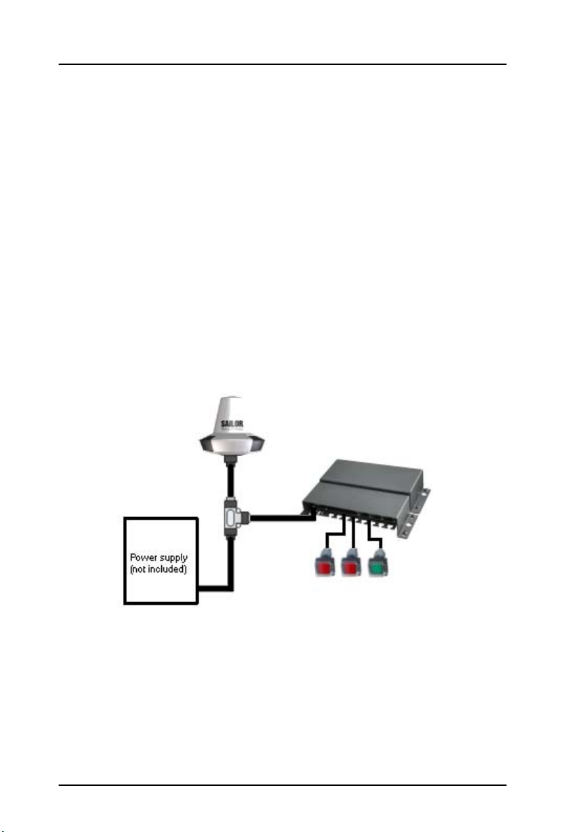
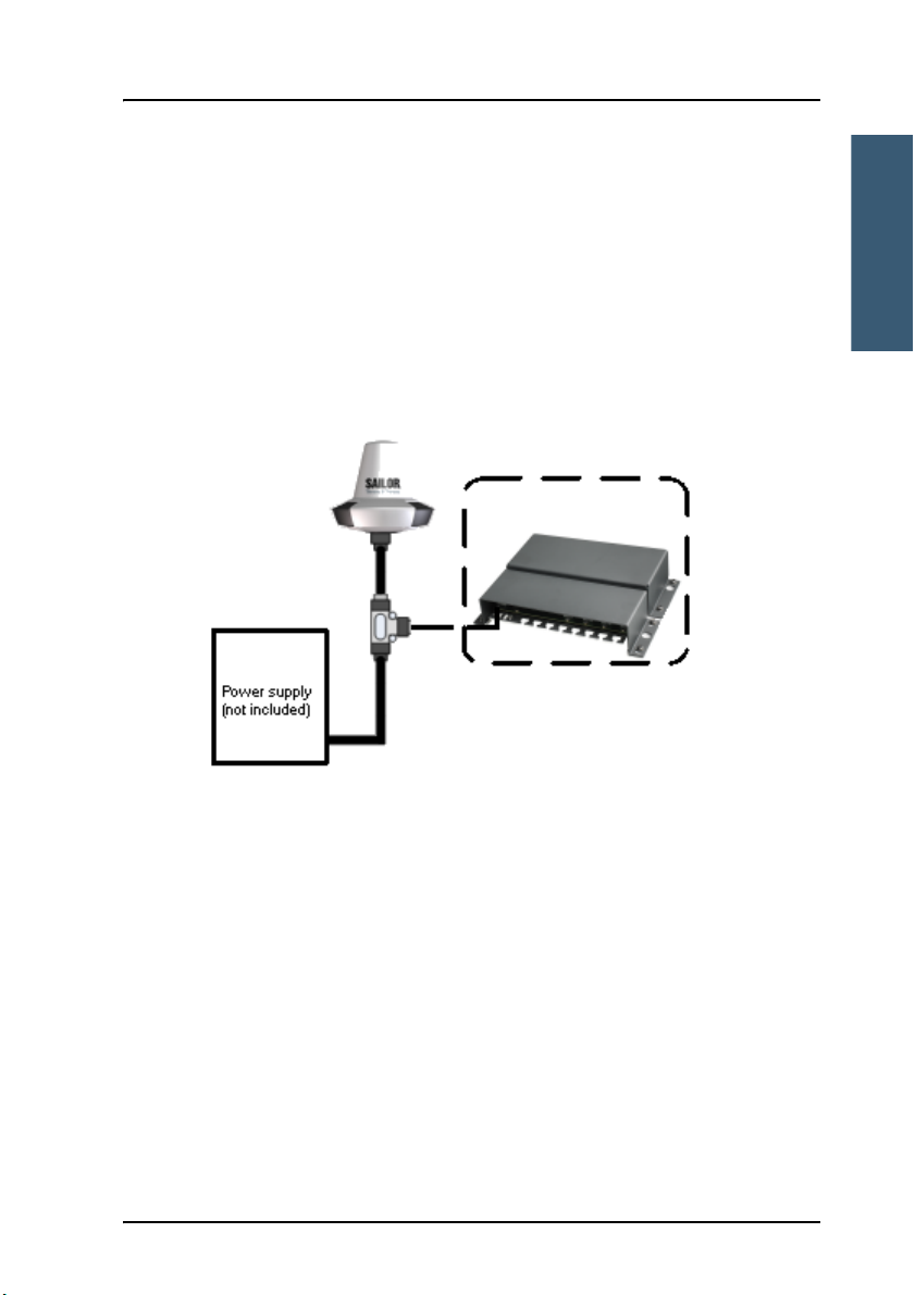
1.1.1 SAILOR 6120 SSA System
The drawing below shows an example of a SAILOR 6120 SSA System.
The SSA (Ship Security Alert) System provides ships with alarm buttons, which
can be activated in case of a piracy or terrorist attack. The alarm is a covert
signal that has no sound and no flashing lights, so it is not seen nor heard by
any intruders on board the ship.
2 SAILOR 6120/30/40/50 system overview
Chapter 1: Introduction
Introduction
SAILOR 3027
LRIT Terminal
Optional
THRANE 6194
The SAILOR 6120 has three SSA buttons (two alarm buttons and one test
button), which connect to the SAILOR 3027 SSA Terminal through the THRANE
6194 Terminal Control Unit. The CAN interface, which connects the SAILOR
3027 SSA Terminal to the THRANE 6194, also provides the power for the
THRANE 6194.
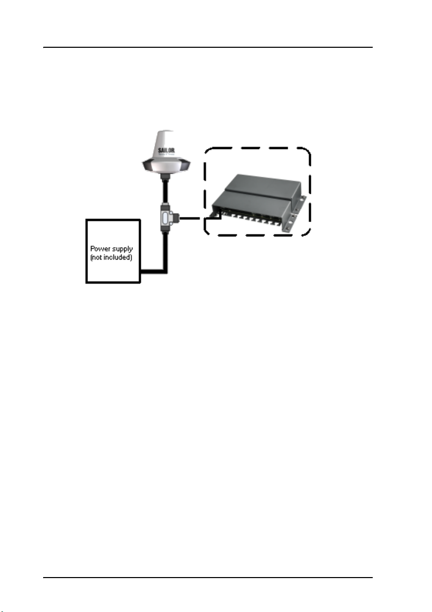
1.1.2 SAILOR 6130 LRIT System
The drawing below shows an example of a SAILOR 6130 LRIT System.
1111
Ships that are subject to the LRIT (Long Range Identification and Tracking)
regulation must report their position to their Flag Administration at least 4
times a day.
In addition to the basic Mini-C functions listed in the next section, the
SAILOR 6130 LRIT System complies with the LRIT regulation and automatically
reports the position of the ship every 6 hours.
When used with a THRANE 6194 Terminal Control Unit, the SAILOR 6140 can be
connected to a computer using either the LAN interface or the RS-232
interface (e.g. for software update).
SAILOR 6120/30/40/50 system overview 3
Chapter 1: Introduction
SAILOR 3027
Maritime Terminal
Optional
THRANE 6194
1.1.3 SAILOR 6140 Maritime System
The drawing below shows an example of a SAILOR 6140 Maritime System.
The SAILOR 6140 is a basic Mini-C System that can be used for tracking and
polling, messaging, logging and EGC (Enhanced Group Call).
When used with a THRANE 6194 Terminal Control Unit, the SAILOR 6140 can be
connected to a computer using either the LAN interface or the RS-232
interface, and to other equipment using the I/O interface of the THRANE 6194.
4 SAILOR 6120/30/40/50 system overview
Chapter 1: Introduction
Introduction
SAILOR 3027
SAILOR 6108
THRANE 6194
SAILOR 6007 Message Terminal or
computer with easyMail
(not included)
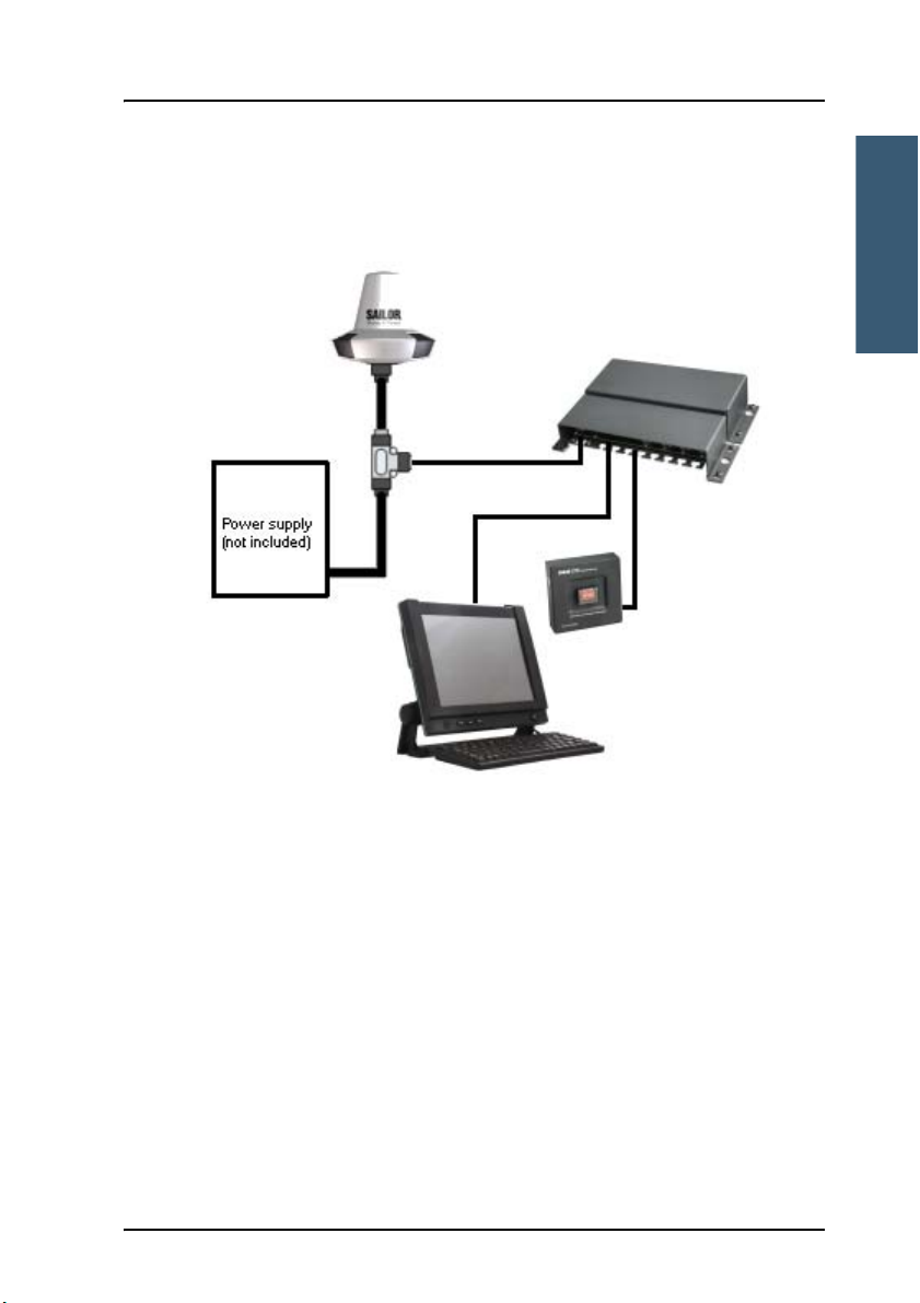
1.1.4 SAILOR 6150 Non-SOLAS System
The drawing below shows an example of a SAILOR 6150 Non-SOLAS System.
1111
In addition to the basic Mini-C functions listed in the previous section, the
SAILOR 6150 can be used in non-SOLAS Distress systems to send Distress
alerts using the SAILOR 6108 Non-SOLAS Alarm Panel or SAILOR 3042E.
In non-SOLAS Distress systems a user interface is mandatory. You can use the
easyMail application installed on a computer or on a SAILOR 6007 Message
Terminal, or you can use a SAILOR 6006 Message Terminal, which has its own
built-in user interface. See Configuration tools on page 48.
SAILOR 6120/30/40/50 system overview 5
Chapter 1: Introduction
1.2 Units in the system
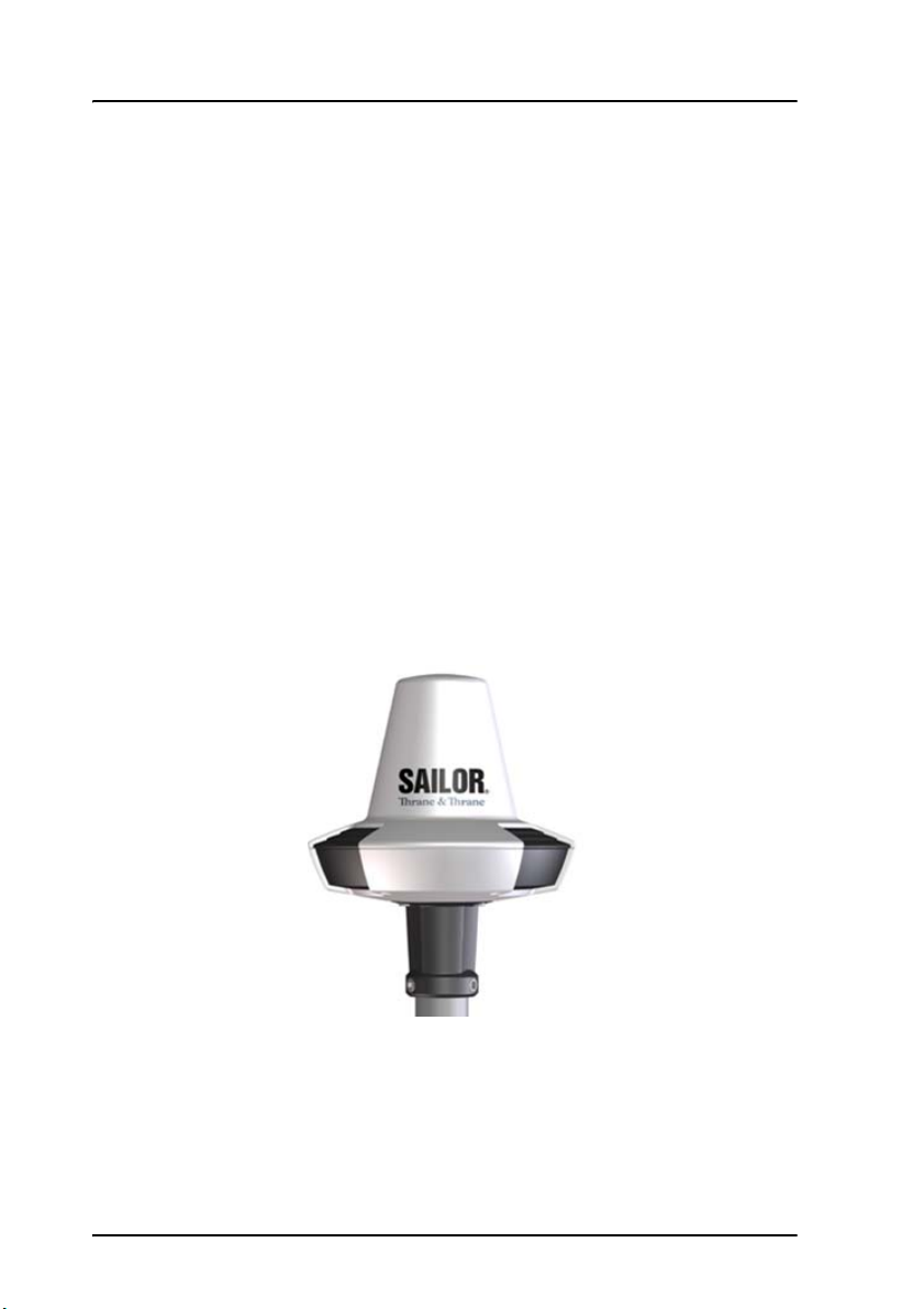
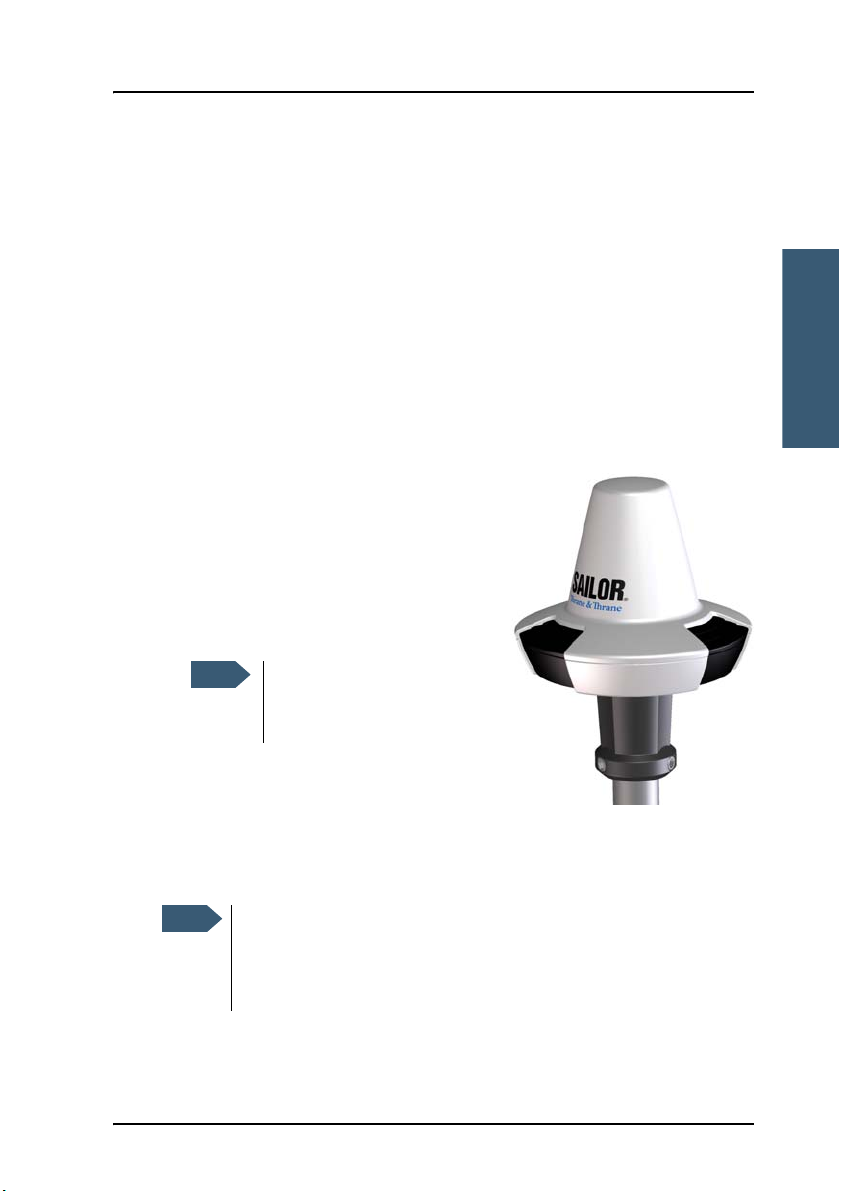
1.2.1 SAILOR 3027 Mini-C Terminal
The SAILOR 3027 comes in different variants for different systems. The
functions are different for each variant but the description below applies to all
off these four variants:
• SAILOR 3027 SSA Terminal
• SAILOR 3027 LRIT Terminal
• SAILOR 3027 Maritime Terminal
• SAILOR 3027 Non-SOLAS Terminal
The SAILOR 3027 Mini-C Terminal is a mobile satellite terminal for the
Inmarsat C system. It has a built-in LNA/HPA and an omni-directional antenna
designed to operate on vessels. The housing is sealed and contains no user
serviceable parts.
The SAILOR 3027 is very compact and is designed to operate in extreme
weather conditions. It has a highly sensitive built-in GPS module with 50
channels. The antenna has an elevation angle of -15°, ensuring optimum
communication even in rough weather.
6 Units in the system
Chapter 1: Introduction
Introduction
The SAILOR 3027 connects to other equipment using a CAN bus interface,
capable of carrying power as well as bi-directional communication.
For information on how to install the SAILOR 3027, see Installing the SAILOR
3027 on page 14.
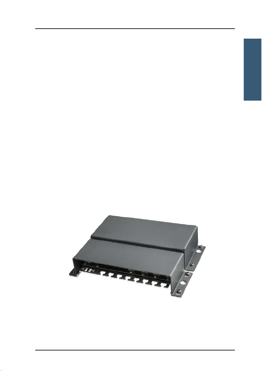
1.2.2 THRANE 6194 Terminal Control Unit
The THRANE 6194 is used for the following purposes:
• For connecting
• covert alert buttons for use in Ship Security Alert (SSA) systems such as
SAILOR 6120, or
• SAILOR 6108 Non-SOLAS Alarm Panels e.g. in Non SOLAS Distress
systems (SAILOR 6150).
• For connecting other equipment that has Ethernet or RS-232 interface with
the SAILOR 3027 terminal, which has a CAN interface.
The power for the THRANE 6194 is supplied through the CAN interface
(extended input range 9-32 V DC).
1111
Units in the system 7
Chapter 1: Introduction
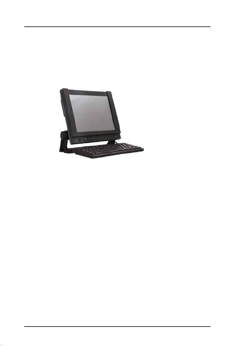
1.2.3 SAILOR 6007 Message Terminal
On the SAILOR 6007 with the easyMail application installed you can read and
write messages, monitor system status, change the configuration and test the
system.
The SAILOR 6007 has a touch-screen interface and can be operated without a
keyboard. You can also connect a keyboard if you prefer that.
An Ethernet interface connects to the SAILOR 3027 Mini-C Terminal through
the THRANE 6194 Terminal Control Unit.
For information on how to install the SAILOR 6007, see SAILOR 6006 and 6007
Message Terminal, Installation manual [2].
For information on how to install and use the easyMail application, see
Configuration using easyMail on page 49.
8 Units in the system
Chapter 1: Introduction
Introduction
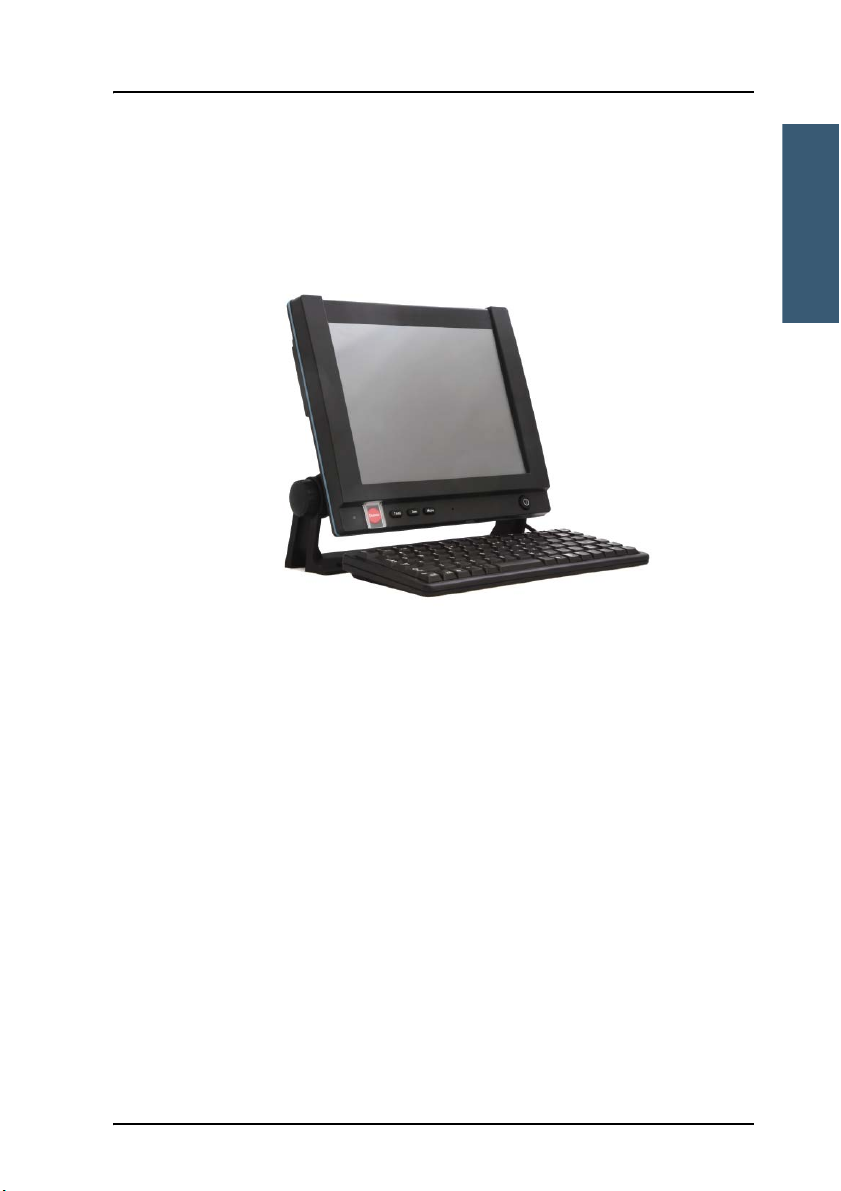
1.2.4 SAILOR 6006 Message Terminal (for SAILOR 6150 only)
With the SAILOR 6006 you can send distress alerts, read and write messages,
monitor system status, change the configuration and test the system. The
SAILOR 6006 has a Distress button for sending Distress alerts.
1111
The SAILOR 6006 has a touch-screen interface and can be operated without a
keyboard.
A CAN interface connects to the SAILOR 3027 Mini-C Terminal and an Ethernet
interface connects to other equipment.
For information on how to install the SAILOR 6006, see SAILOR 6006 and 6007
Message Terminal, Installation manual [2].
Units in the system 9

Chapter 1: Introduction
10 Units in the system

Chapter 2
Installing the system
Installing the system 2
This chapter describes the mechanical installation of the Mini-C Terminal. For
information on cables and wiring of the system, see Connecting the system on
page 21.
For information how to configure and use the system, see Initial configuration
on page 52 and SAILOR 6120/30/40/50 System, User manual [1].
The following sections describe
• Unpacking
• General installation requirements
• Installing the SAILOR 3027
Mechanical installation of other units in the system, e.g. the THRANE 6194
Terminal Control Unit, is described in the individual installation manuals for
the units. The names and numbers of the manuals are listed in Related
documents on page v in the beginning of this manual.
2222
2.1 Unpacking
2.1.1 Initial inspection
Inspect the shipping carton immediately upon receipt for evidence of damage
during transport. If the shipping carton is severely damaged or water stained,
11

Chapter 2: Installing the system
request that the carrier's agent be present when opening the carton. Save the
carton packing material for future use.
Warning! To avoid electric shock, do not apply power to the system if
there is any sign of shipping damage to any part of the
front or rear panel or the outer cover. Read the safety
summary at the front of this manual before installing or
operating the system.
After unpacking the system, inspect it thoroughly for hidden damage and
loose components or fittings. If the contents are incomplete, if there is
mechanical damage or defect, or if the system does not work properly, notify
your dealer.
2.1.2 What’s in the delivery
The following items are included in the delivery:
• SAILOR 3027 Mini-C Terminal, one of the following variants:
• SAILOR 3027 SSA Terminal
• SAILOR 3027 LRIT Terminal
• SAILOR 3027 Maritime Terminal
• SAILOR 3027 Non-SOLAS Terminal
• 1 Inch Pipe Adaptor and screw kit for Pipe Adaptor.
• Accessories kit including cables and connectors. For details, see Cables and
connectors on page 27. Not included with SAILOR 6140.
• For SAILOR 6120 SSA System and SAILOR 6150 Non-SOLAS System only:
THRANE 6194 Terminal Control Unit.
• For SAILOR 6150 Non-SOLAS System only: SAILOR 6108 Non-SOLAS Alarm
Panel.
•Manuals:
• SAILOR 6120/30/40/50 Mini-C System, Installation manual
(this manual) and
• SAILOR 6120/30/40/50 Mini-C System, User manual
12 Unpacking
Chapter 2: Installing the system
Installing the system
Important
Important
2.2 General installation requirements
Only the SAILOR 3027 Mini-C Terminal must be placed
outdoors. Place all other units in the system indoors! For
information on environmental requirements to the units, refer
to Technical specifications on page 69 or the individual
installation manuals for the units.
2.2.1 Power requirements
A SAILOR 6120/30/40/50 Mini-C System operates on 9-32 V DC. You may use
any power supply or battery that meets the power requirements listed in this
section and in Appendix A, Technical specifications.
If any additional NMEA2000 equipment is connected to the
CAN bus, the power supply must be 15 V DC (nominal). To
convert your power supply to 15 V DC you may use a
SAILOR 6090 Power Converter or a SAILOR 6081 PSU and
Charger from Thrane & Thrane.
2222
Power consumption
The total power consumption varies primarily due to system activities. If you
are using a battery, make sure it is capable of providing the required power.
As a guideline, note the power consumption of the following equipment:
Unit Idle power Max. power
SAILOR 3027 Mini-C Terminal 1.85 W 30 W
THRANE 6194 Terminal Control Unit 1 W 7 W
SAILOR 6006 Message Terminal
(12 V DC - 24 V DC)
General installation requirements 13
12 W 20 W

Chapter 2: Installing the system
2.3 Installing the SAILOR 3027
2.3.1 Placing the SAILOR 3027 Mini-C Terminal
Place the terminal outdoors on the ship. Before mounting the terminal,
consider the following:
• Safety distance: 1 ft. (0.3 m).
Place the terminal so that no person can accidently get closer to the
terminal than the safety distance 1 ft. (0.3 m).
• Distance to exhaust fumes.
Do not place the terminal close to the funnel directly exposed to exhaust
fumes.
• Distance to heat.
Do not place the terminal close to any heat source.
• Distance to other equipment.
Keep the following distances between the terminal and other equipment:
• Compass safe distance: > 5 m (distance to magnetic compass)
• HF antennas: > 5 m
• VHF antennas: > 4 m
• Other Inmarsat C terminals: > 0.5 m
14 Installing the SAILOR 3027
Chapter 2: Installing the system
Installing the system
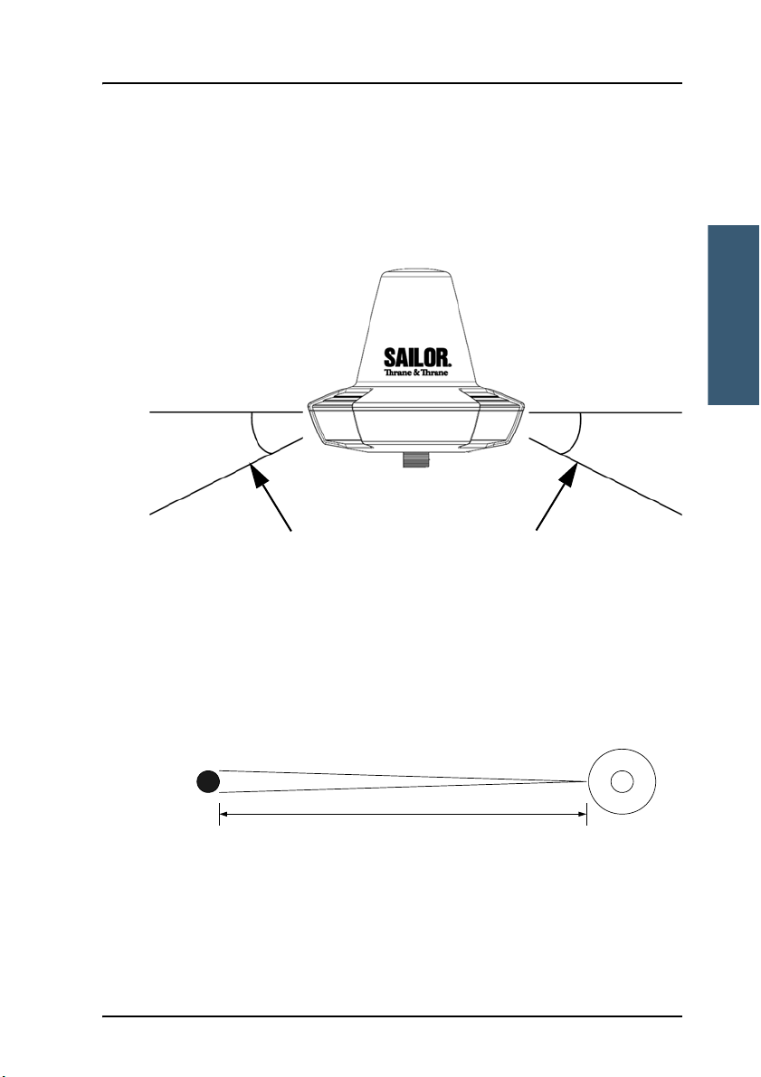
Zenith
Horizon
15°
Horizon
15°
Obstructions should be below these lines
2.9 m apart to ensure the obstruction covers no more than 2°
SAILOR 3027
Mini-C Transceiver
0.1 m diameter
obstruction
• Line of sight.
Place the terminal in an area as free from obstructions as possible in all
directions down to 15° below the horizon.
2222
If obstructions cannot be avoided, place the receiver so that the
obstruction covers no more than 2° of the view from the terminal. To
obtain this, the distance between the obstruction and the terminal must be
minimum 29 x diameter of the obstruction.
Example: The obstruction is a pole of 0.1 m diameter. This means the
terminal must be placed 29 x 0.1 m = 2.9 m from the obstruction.
Installing the SAILOR 3027 15

Chapter 2: Installing the system
Important
• Power source available.
The power source must be placed as close as possible to the terminal.
• Grounding available.
Make sure that the shield of the CAN cable is connected to a proper
ground, i.e. the ship’s structure/hull. This is very important in order to
protect persons and equipment from lightning and safely bypass
interference from Radar, VHF/MF/HF radio equipment and other
environmental sources of interference.
Do not make the ground connection at the SAILOR 3027
end of the CAN cable. Instead, connect the shield of the
CAN cable to ship ground at the power supply.
16 Installing the SAILOR 3027
Chapter 2: Installing the system
Installing the system
Note
Note
2.3.2 Mounting the SAILOR 3027 Mini-C Terminal
The Mini-C Terminal has one CAN connector and is designed primarily for
pole mounting.
• For mechanical drawings, see Mechanical outline drawing, SAILOR 3027
Mini-C Terminal on page 20.
• For information on wiring, see Connecting the system on page 21.
• For part numbers of the mounting accessories, see Available parts on
page 67.
Pole mount 1”
The pole mount kit is included with your
Mini-C Terminal. Follow the instructions
included with the pole mount kit.
1. Lead the cable through the pole and pole
mount adapter.
2222
2. Connect the CAN cable to the terminal.
The connector is waterproof.
Do not attempt to seal the
connection any further.
3. Mount cable relief for the CAN cable.
4. Mount the adapter on the terminal using
screws.
5. Tighten the adapter to the pole.
You cannot access the CAN connector when the pole mount adapter
is mounted on theMini-C Terminal. If at a later stage you need to
disconnect/connect the cable, the pole mount adapter must first be
removed from the terminal.
You may use the adjustable pole/railing mount as an alternative to the pole
mount. See the next section for details.
Installing the SAILOR 3027 17
 Loading...