

Thrane&Thrane SAILOR 6110 Installation Manual
INSTALLATION MANUAL
SAILOR 6110 GMDSS System


SAILOR 6110 GMDSS System
Installation manual
Document number: 98-130752-A
Release date: December 22, 2010

Disclaimer
Any responsibility or liability for loss or damage in connection with the use of this
product and the accompanying documentation is disclaimed by Thrane & Thrane. The
information in this manual is provided for information purposes only, is subject to
change without notice and may contain errors or inaccuracies.
Manuals issued by Thrane & Thrane are periodically revised and updated. Anyone
relying on this information should acquire the most current version e.g. from
http://www.thrane.com or from the distributor.
Thrane & Thrane is not responsible for the content or accuracy of any translations or
reproductions, in whole or in part, of this manual from any other source.
Copyright
© 2010 Thrane & Thrane A/S. All rights reserved.
Trademark Acknowledgements
• Thrane & Thrane is a registered trademark of Thrane & Thrane A/S in the European
Union and the United States.
• Inmarsat is a registered trademark of the International Maritime Satellite
Organisation (IMSO) and is licensed by IMSO to Inmarsat Limited and Inmarsat
Ventures plc.
• SAILOR is a registered trademark of Thrane & Thrane A/S in the European Union, the
United States and other countries.
• Other product and company names mentioned in this manual may be trademarks or
trade names of their respective owners.
Safety summary 1
The following general safety precautions must be observed during all
phases of operation, service and repair of this equipment. Failure to comply
with these precautions or with specific warnings elsewhere in this manual
violates safety standards of design, manufacture and intended use of the
equipment. Thrane & Thrane assumes no liability for the customer's failure
to comply with these requirements.
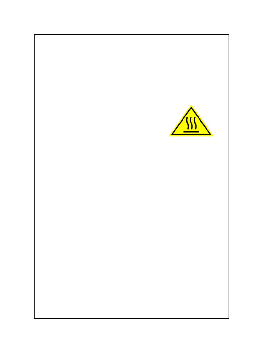
Observe marked areas
Under extreme heat conditions do not touch areas of
units that are marked with this symbol, as it may
result in injury.
Microwave radiation hazards
During transmission the antenna in this system radiates Microwave
Power.This radiation may be hazardous to humans close to the antenna.
When the system is powered, make sure that nobody gets closer than the
recommended minimum safety distance of 0.3 meters (1 ft.).
Keep away from live circuits
Operating personnel must not remove equipment covers. Only qualified
maintenance personal must make component replacement and internal
adjustment. Under certain conditions, dangerous voltages may exist even
with the cable removed. To avoid injuries, always disconnect power and
discharge circuits before touching them.
Compass safe distance
Minimum safety distance: 5 m from the GMDSS Terminal.
Failure to comply with the rules above will void the warranty!
iii

About the manual 2
Intended readers
This manual is an installation manual for the SAILOR 6110 GMDSS
System. The manual is intended for installers of the system and
service personnel. Personnel installing or servicing the system
must be properly trained and authorized by Thrane & Thrane. It is
important that you observe all safety requirements listed in the
beginning of this manual, and install the system according to the
guidelines in this manual.
Manual overview
Note that this manual does not cover how to use the system. For
information on usage refer to the user manual. Part numbers for
related manuals are listed in the next section.
This manual has the following chapters:
• Introduction contains an overview of the system.
• Unpacking and activation describes initial inspection and
explains how to activate the service.
• Installing the system explains how to mount the units.
• Connecting the system explains how to connect the units in the
system and shows wiring, pin-out and cable requirements.
• Installation check and test contains a check list for verifying the
physical installation and guidelines for testing the installation.
• Maintenance contains guidelines for handling, maintaining
and repacking the SAILOR 6110 system.
iv
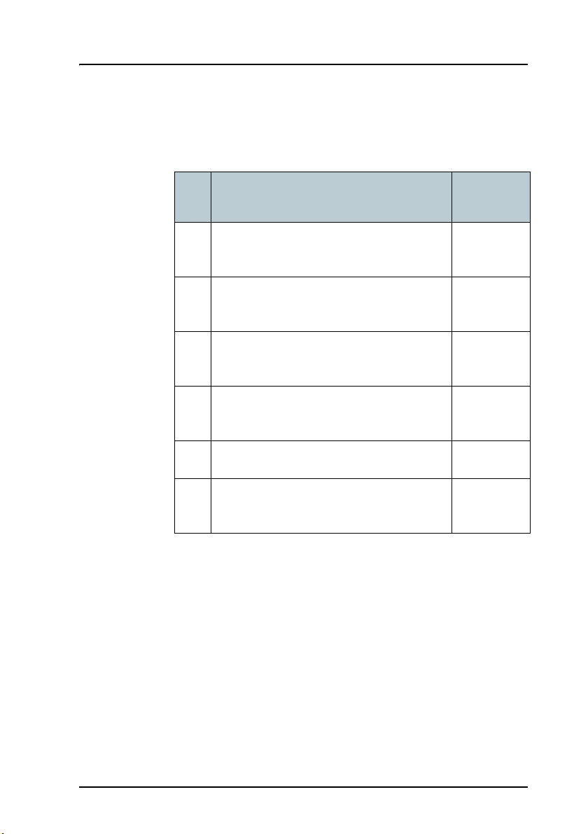
Related documents
The below list shows the documents related to this manual and to
the SAILOR 6110 GMDSS System.
Ref Title and description
[1] SAILOR 6110 GMDSS System,
User manual
[2] SAILOR 6006 and 6007 Message Terminal,
Installation manual
[3] SAILOR 6101 and 6103 Alarm Panel,
Installation and user manual
[4] SAILOR 6081 PSU and Charger,
Installation and user manual
[5] System 6000 Console, Installation manual 98-131571
[6] THRANE 6194 Terminal Control Unit,
Installation and user manual
Document
number
98-130753
98-130088
98-130981
98-130980
98-131593
v

Typography
In this manual, typography is used as indicated below:
Bold is used for the following purposes:
• To emphasize words.
Example: “Do not touch the antenna”.
• To indicate what the user should select in the user interface.
Example: “Select SETTINGS > LAN”.
Italic is used to emphasize the paragraph title in cross-references.
Example: “For further information, see Connecting Cables on
page...”.
COURIER is used to indicate low level commands or text in the
display.
Example: “The display shows Distress”.
vi

Contents
Chapter 1 Introduction
1.1 SAILOR 6110 system overview .....................................2
1.2 SAILOR 3027 GMDSS Terminal ...................................3
1.3 SAILOR 6006 Message Terminal ................................4
1.4 SAILOR 6081 PSU and Charger ...................................5
1.5 SAILOR 1252 Printer ...................................................6
1.6 SAILOR 6197 Ethernet switch ......................................6
1.7 SAILOR 6101/6103 Alarm Panel ...................................7
1.8 SSA option .................................................................8
Chapter 2 Unpacking and activation
2.1 Initial inspection ........................................................9
2.2 Registering your SAILOR 3027 .................................. 10
Chapter 3 Installing the system
3.1 General installation requirements .............................14
3.2 Mounting the SAILOR 3027 .......................................16
3.3 Mounting the SAILOR 1252 printer ...........................23
Chapter 4 Connecting the system
4.1 Connecting the units ................................................ 27
4.2 Grounding the units ..................................................31
4.3 The CAN backbone ...................................................33
4.4 Connecting power ....................................................34
4.5 Connectors and pin-out ...........................................38
vii

Contents
Chapter 5 Installation check and test
5.1 Installation check list ...............................................47
5.2 Testing the system ...................................................49
5.3 Generating a diagnostic report .................................55
Chapter 6 Maintenance
6.1 Maintenance guidelines ...........................................57
6.2 Repacking for shipment .......................................... 58
6.3 Available parts .........................................................59
App. A Technical specifications
A.1 SAILOR 6110 system specifications ............................ 61
A.2 SAILOR 3027 specifications .......................................62
Glossary .........................................................................................65
Index ........................................................................................ 69
viii

Chapter 1
Introduction
Introduction 1
This chapter introduces the SAILOR 6110 system and briefly describes each unit
in the system. It has the following sections:
• SAILOR 6110 system overview
• SAILOR 3027 GMDSS Terminal
• SAILOR 6006 Message Terminal
• SAILOR 6081 PSU and Charger
• SAILOR 1252 Printer
• SAILOR 6197 Ethernet switch
• SAILOR 6101/6103 Alarm Panel
• SSA option
1111
1
Chapter 1: Introduction
SAILOR 6081
SAILOR 6006
SAILOR 3027
Inline micro
SAILOR
SAILOR
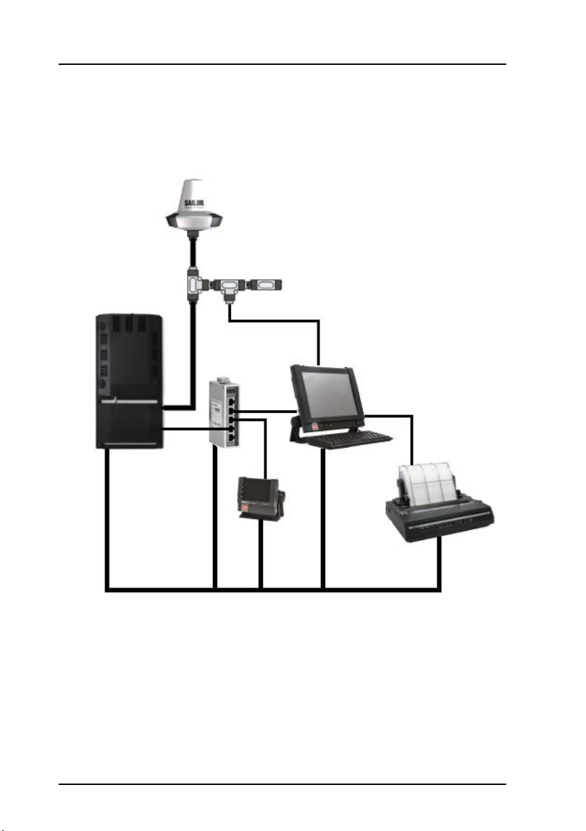
SAILOR 6110 GMDSS system
29 V DC
USB
15 V DC
LAN
LAN
LAN
CAN
CAN
6101/6103
1252
termination
SAILOR 6197
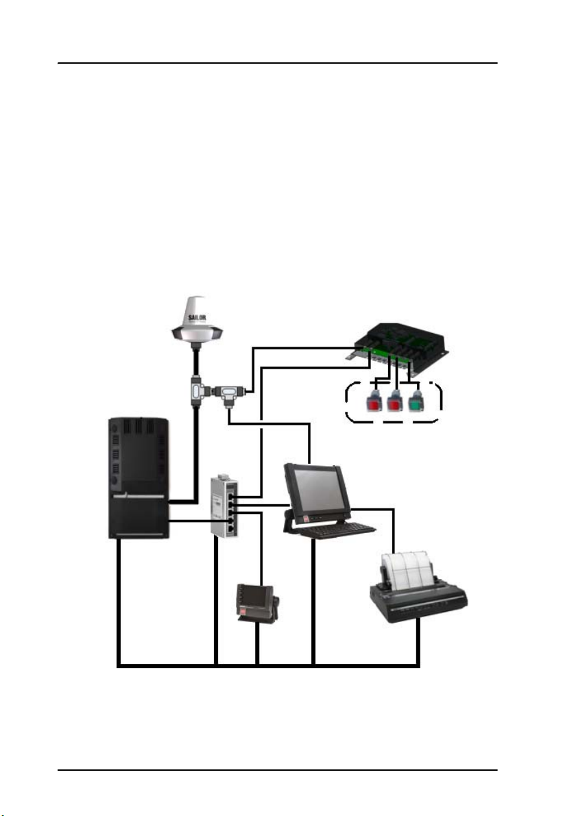
1.1 SAILOR 6110 system overview
The drawing below shows an example of a SAILOR 6110 system.
The SAILOR 6110 is a Global Maritime Distress Safety System (GMDSS) used for
sending and receiving messages and distress alerts through the Inmarsat C
satellite network.
Each unit is briefly described in the following sections. For a description of the
services supported by the Inmarsat C system and the SAILOR 6110 system, see
the user manual for the SAILOR 6110 GMDSS System [1].
2 SAILOR 6110 system overview
Chapter 1: Introduction
Introduction
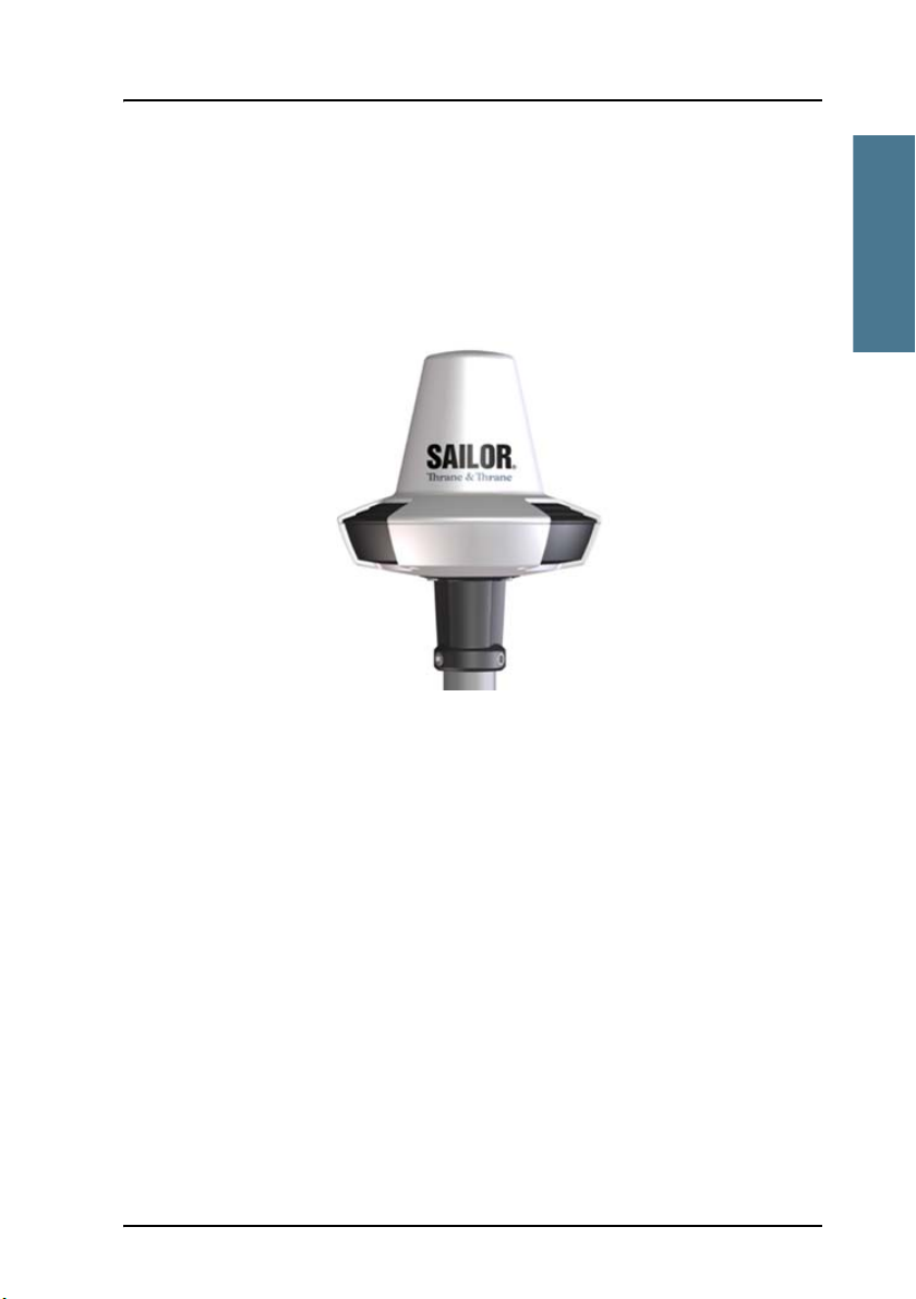
1.2 SAILOR 3027 GMDSS Terminal
The SAILOR 3027 is a GMDSS approved Inmarsat GMDSS Terminal for the
SAILOR 6110 system. It has a built-in LNA/HPA and an omni-directional
antenna designed to operate on vessels. The housing is sealed and contains
no user serviceable parts.
1111
The SAILOR 3027 is very compact and is designed to operate in extreme
weather conditions. It has a highly sensitive built-in GPS module with 50
channels (Galileo ready). The antenna has an elevation angle of -15°,
ensuring optimum communication even in rough weather.
The SAILOR 3027 connects to other equipment using a CAN bus interface,
capable of carrying power as well as bi-directional communication.
For information on how to install the SAILOR 3027, see Mounting the SAILOR
3027 on page 16.
SAILOR 3027 GMDSS Terminal 3
Chapter 1: Introduction
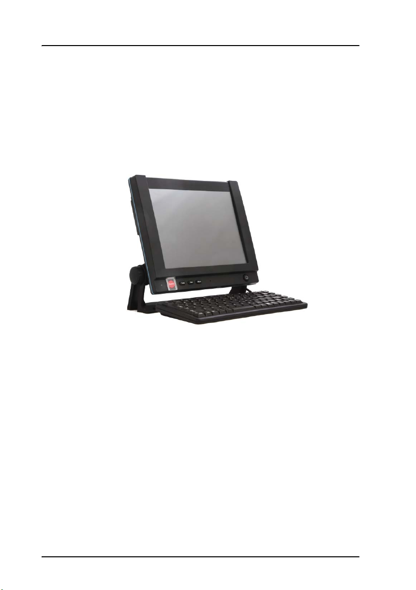
1.3 SAILOR 6006 Message Terminal
The SAILOR 6006 Message Terminal is a GMDSS approved message terminal
for the SAILOR 6110 system. With the SAILOR 6006 you can send distress alerts,
read and write messages, monitor system status, change the configuration
and test the system. The SAILOR 6006 has a Distress button for sending
distress alerts.
The SAILOR 6006 has a touch-screen interface and can be operated without a
keyboard. However, a keyboard is mandatory in a GMDSS system.
A CAN interface connects to the SAILOR 3027 GMDSS Terminal and an
Ethernet interface connects to other equipment, such as alarm panels.
For information on how to install the SAILOR 6006, see the installation manual
enclosed with the SAILOR 6006 [2].
4 SAILOR 6006 Message Terminal
Chapter 1: Introduction
Introduction
Note
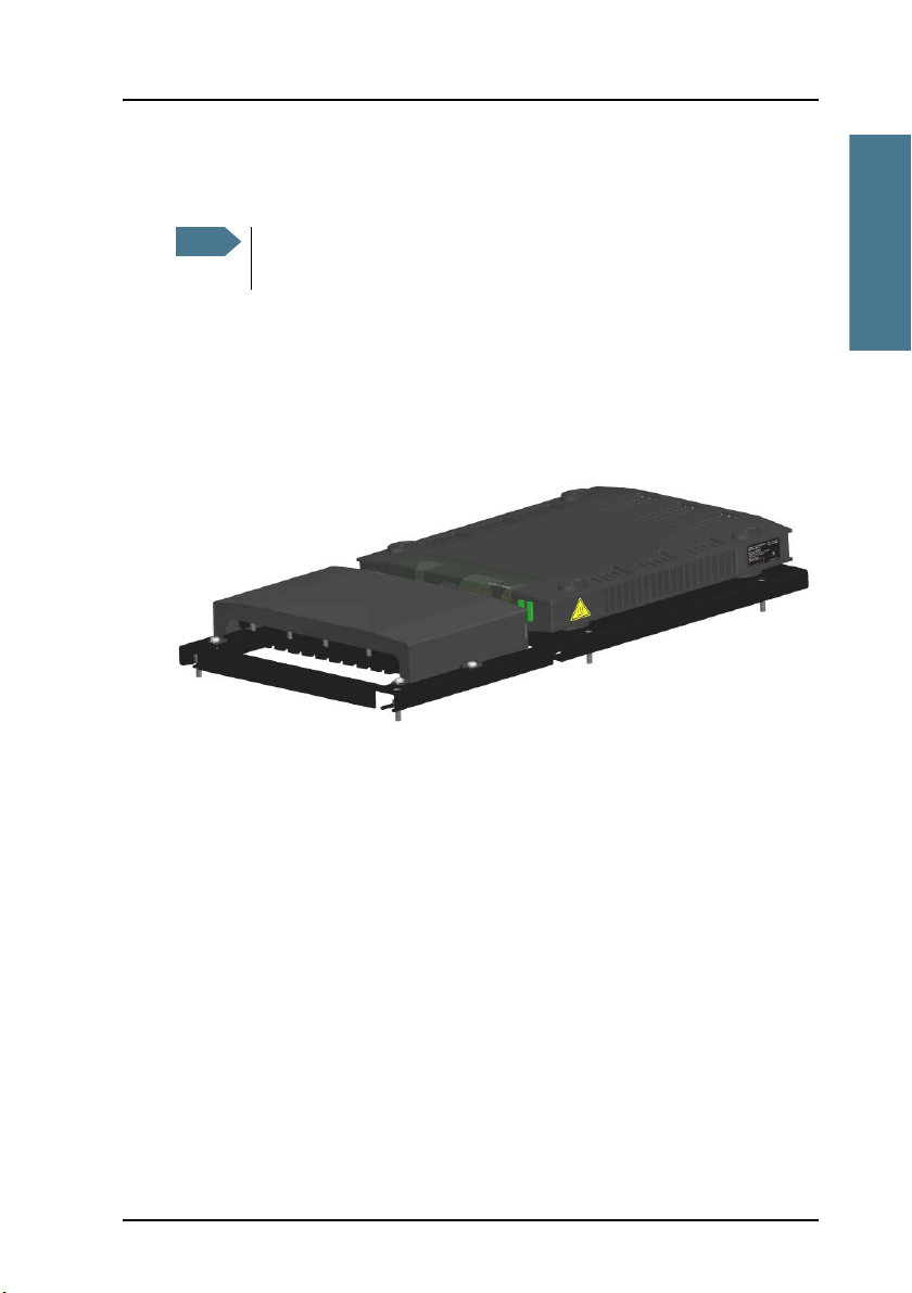
1.4 SAILOR 6081 PSU and Charger
If you are using a different type of power supply than the
SAILOR 6081, you must install a voltage monitor.
The SAILOR 6081 PSU and Charger is used to supply power to the units in the
SAILOR 6110 GMDSS System. It has five DC outputs of 24 V DC to 31.5 V DC
(nominal 29 V DC) each and provides 300 W continuous (370 W peak). It also
has a 15 V DC output, which should be used to supply power to the
GMDSS Terminal through the CAN bus.
1111
The SAILOR 6081 PSU and Charger provides automatic switch-over to a
connected backup battery if 115/230 VAC is not available. It also has a charger
function for charging the battery when 115/230 VAC is available. Note that a
backup battery is mandatory in the GMDSS System.
On the SAILOR 6006 you can read status information such as AC alarm,
backup battery status and other status information from the SAILOR 6081,
through the Ethernet connection.
For further information on the SAILOR 6081, see the manual enclosed with the
SAILOR 6081 [4].
SAILOR 6081 PSU and Charger 5
Chapter 1: Introduction
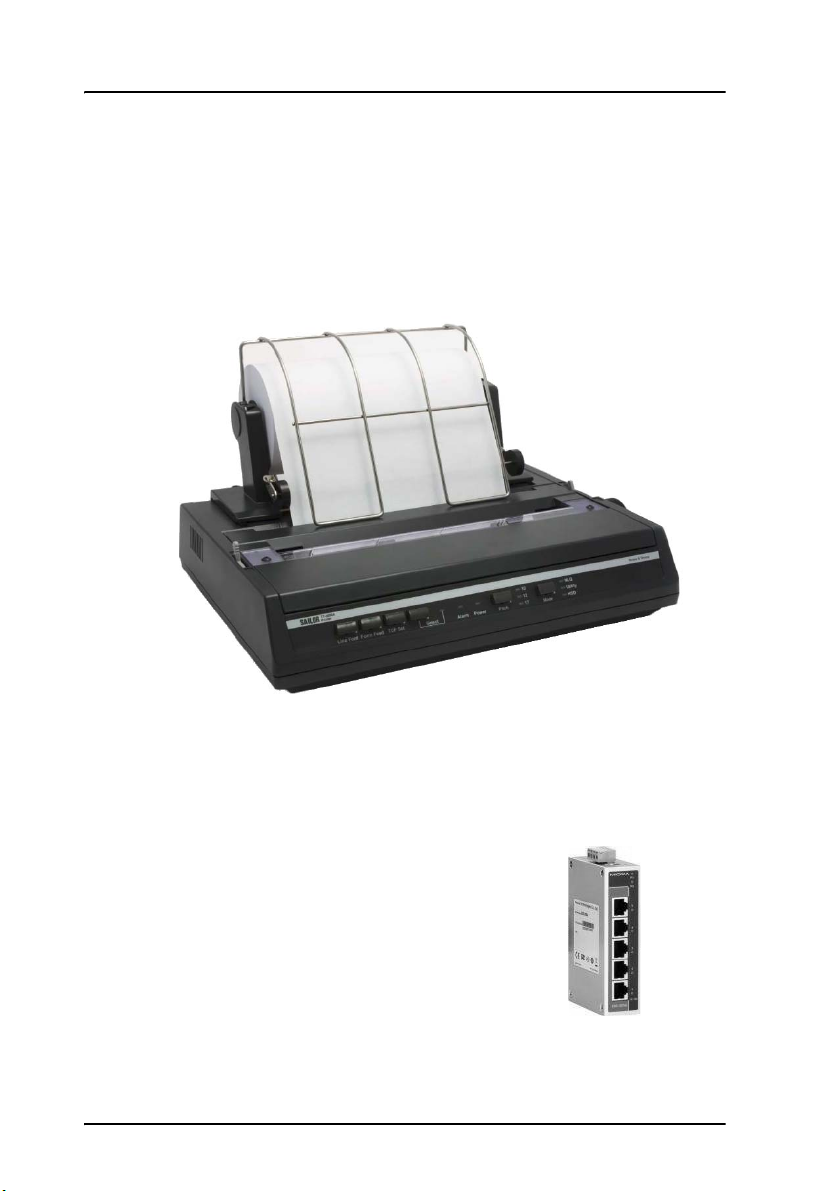
1.5 SAILOR 1252 Printer
The SAILOR 1252 printer is a standard matrix printer which connects to one of
the USB connectors on the SAILOR 6006. In the SAILOR 6110 system it is
primarily used to print SafetyNet EGCs with Distress priority.
1.6 SAILOR 6197 Ethernet switch
The Ethernet switch connects the system units that
have an Ethernet interface.
In the SAILOR 6110 system, the local network is
primarily used for monitoring purposes, alarm
reporting and service.
6 SAILOR 1252 Printer
Chapter 1: Introduction
Introduction
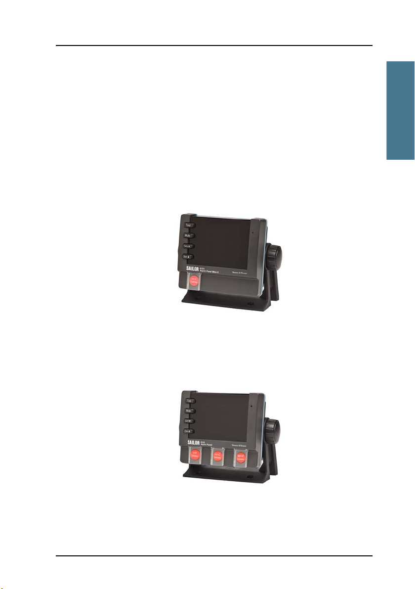
1.7 SAILOR 6101/6103 Alarm Panel
In addition to the Distress button on the SAILOR 6006, you must have one
more distress button in order to comply with GMDSS regulations. For this
purpose you can use an alarm panel. Two types of alarm panel are available
from Thrane & Thrane:
• SAILOR 6101 Alarm Panel
This SAILOR 6101 has one Distress button, used for remote initiation of
distress alert transmissions and for indication of incoming distress and
urgency messages on Inmarsat-C GMDSS systems.
1111
• SAILOR 6103 Multi Alarm Panel
Like the SAILOR 6101, the SAILOR 6103 is also used for remote initiation of
distress alert transmissions and for indication of incoming distress and
urgency messages, but the SAILOR 6103 is designed for use with both VHF,
MF/HF and Inmarsat-C and has 3 Distress buttons, one for each system.
For further information on the SAILOR 6101/6103, see the manual enclosed
with your alarm panel [3].
SAILOR 6101/6103 Alarm Panel 7
Chapter 1: Introduction
SAILOR 6081
SAILOR 6006
SAILOR 3027
CAN
SAILOR
SAILOR
CAN
SAILOR 6110 GMDSS system with SSA
SAILOR
29 V DC
15 V DC
USB
LAN
LAN
LAN
LAN
1252
LAN
6101/6103
THRANE 6194
6197
SAILOR 6100-913 SSA Kit/
SAILOR 6100-916 SSA US Kit
1.8 SSA option
The Ship Security Alert System provides ships with alarm buttons, which can
be activated in case of a piracy or terrorist attack. The alarm is a covert signal
that has no sound and no flashing lights, so it is not seen nor heard by any
intruders on board the ship.
The SSA option consists of three SSA buttons (two alarm buttons and one test
button). It connects to the SAILOR 6110 system through the THRANE 6194
Terminal Control Unit. The CAN interface, which connects the SAILOR 6110
system to the THRANE 6194, also provides the power for the SSA option.
The GMDSS Terminal must be configured with the recipient(s) of the Ship
Security Alert. For further information on the SSA option, refer to the manual
for the THRANE 6194 [6].
8 SSA option
Chapter 2
Unpacking and activation
Unpacking and activation 2
This chapter describes initial inspection of the SAILOR 6110 system and
provides information on how to register the system for service activation. It
has the following sections:
• Initial inspection
• Registering your SAILOR 3027
2.1 Initial inspection
Inspect the shipping carton immediately upon receipt for evidence of damage
during the transport. If the shipping carton is severely damaged or water
stained, request the carrier's agent to be present when opening the carton.
Save the carton and packing material for future use.
2222
Warning! To avoid hazardous electric shock, do not perform
electrical tests if there is any sign of shipping damage to
the outer cover. Read the safety summary at the front of
this manual before installing or operating the SAILOR 6110
system.
Check that the contents of the shipment are as listed in the enclosed packing
list. If the contents are incomplete, if there is mechanical damage or defect, or
if the system components do not work properly, notify your dealer.
After you unpack the system do as follows:
• Inspect the system thoroughly for hidden damaged or loose components or
fittings.
• Inspect the cable harness for stress, loose or broken wires, and broken
cable ties.
• Examine all the components for loose or missing hardware.
• Fasten any loose hardware.
9

Chapter 2: Unpacking and activation
Note
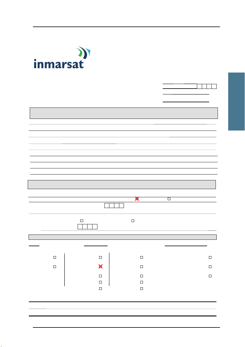
2.2 Registering your SAILOR 3027
2.2.1 Service Activation Registration Form
Before using the SAILOR 3027 GMDSS Terminal on the Inmarsat C system you
must register the terminal to the system.
In most cases the distributor registers the system for the customer.
For this purpose, use the SARF (Service Activation Registration Form) supplied
with the SAILOR 3027. A copy of page 1 of the SARF is shown in the next page.
As a guide, some of the most important fields are filled in with red color.
The SARF for registration of Maritime MES (Mobile Earth Station - in this case
the SAILOR 3027) can also be found on www.inmarsat.com/Support under
Activation, including notes on how to complete the maritime form.
The Service Activation Registration Form contains different abbreviations that
are explained here.
The SAILOR 3027 must be registered at either a PSA company or directly to the
ISP. A PSA is a company handling the activation of Inmarsat mobiles and is
short for Point of Service Activation. ISP is the company that provides the
Inmarsat service and is short for Inmarsat Service Provider. In many cases the
PSA and ISP is the same company that also operates a Land Earth Station
(LES). The local PSA or ISP can be obtained by following the guidelines in the
registration form.
The Service Activation Registration Form also includes information needed to
find out how to pay the bill for the Inmarsat C service. This payment will be
made directly to the Accounting Authority. In many cases the Accounting
Authority (AA) is also the same company as the Inmarsat Service Provider
(ISP).
In addition to the general information like name, address, etc. the ISN of the
SAILOR 3027 must be specified. The ISN is found on the Delivery Note and on
the label in the bottom of the SAILOR 3027 GMDSS Terminal.
10 Registering your SAILOR 3027
Chapter 2: Unpacking and activation
Unpacking and activation
Registration for service activation
of Maritime Mobile Earth Station
PSA use only code
Sections 1-4, 6 and 8 are to be completed by all customers Application number
Tick Boxes as appropriate.
Please write in block capitals Date Day Month Year
Customer’s reference number
Your name or the name of your organisation:
Address:
Town/city: State/province:
Post/ZIP code: Country:
Telephone + Country code ( ) Area code ( ) Telephone number ( )
Facsimile + Country Code ( ) Area code ( ) Facsimile number ( )
Email address:
Contact person:
Title: Department:
What is their telephone number and/or extension? + Count ry code ( ) Area code ( ) Telephone number ( )
Note: ALL MARITIME MESs that are part of GMDSS installations MUST have an Accounting Authority as the billing entity,
Apart from the FLEET F77 MES which may use either an ISP or an AA as the billing entity.
Is the MES part of a GMDSS installation? Yes No
If YES, enter the Accounting Authority Code (AAIC):
If Fleet F77 please see the Note above.
If t he Code is unknown, enter the name of the AA:
If NO, have you arranged payment of calls for this MES through (tick one)
(a) Ac counting Authority (AA)
(b) Inmarsat Service Provider (ISP)
Enter I SP or AA Code:
If t he Code is unknown enter the name of the ISP or AA:
NOTE: If the terminal is activated as Maritime Fixed and placed on a vessel, you could be Endangering Lives At Sea.
Environment usage The System What will be the primary use of the MES?
Maritime
Inmarsat-B Trading Yachts
Maritime Fixed
Inmarsat-C/mini C Passenger/Cruise Other (IMO Num ber Mandatory)
Inmarsat-M
Offshore Other (IMO Num ber NOT Mandatory)
Inmarsat mini-M
Government please specify
Inmarsat Fleet
Fishing
What will be the country of registry of this MES?
Mobile Earth Station (MES) manufacturer Mobile Earth Station (MES) model
1.Your details (See note A)
PLEASE NOTIFY YOUR PSA IF ANY OF THESE DETAILS CHANGE OR YOU ARE NO LONGER THE OWNER OF
THE INMARSAT EQUIPMENT. (THIS IS A LEGAL REQUIREMENT AS STATED IN THE INMARSAT TERMS AND CONDITIONS WHICH ARE
2. Paying the bill (See note B)
PLEASE NOTIFY YOUR PSA URGENTLY IF YOU CHANGE YOUR BILLING ENTITY (AA or ISP.) (THIS IS A
LEGAL REQUIREMENT AS STATED IN THE INMARSAT TERMS AND CONDITIONS WHICH ARE ATTACHED TO THE SARF)
3. What type of Mobile Earth Station (MES) are you registering? (See note C)
Thrane & Thrane A/S
SAILOR 3027 GMDSS Terminal
ATTACHED TO THE BACK OF THIS SARF)
Registering your SAILOR 3027 11
2222
Chapter 2: Unpacking and activation
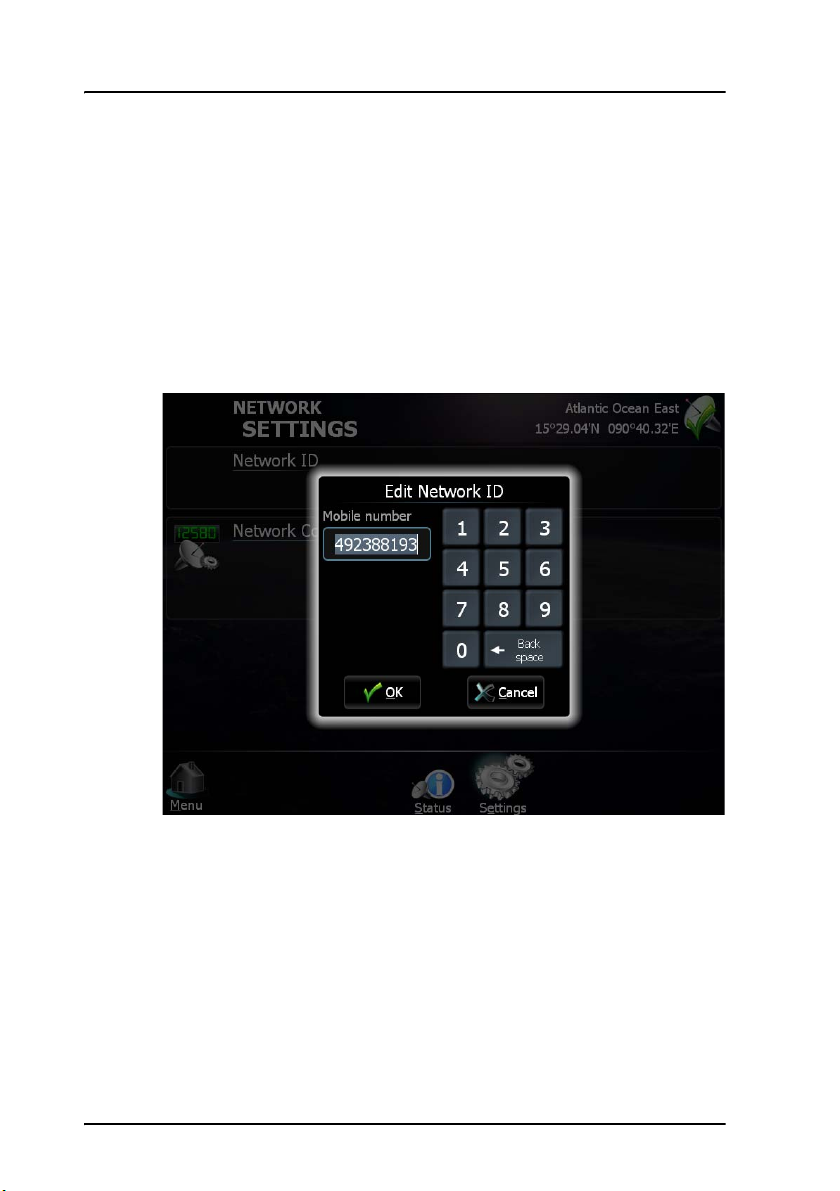
2.2.2 Entering the mobile number in the SAILOR 3027
When the SAILOR 3027 GMDSS Terminal is registered at the ISP, the ISP
returns a mobile number for the SAILOR 3027. This mobile number must be
entered in the SAILOR 3027 using the SAILOR 6006 Message Terminal.
To enter the mobile number in the SAILOR 3027, do as follows:
1. In the Message Terminal display, select Network.
2. Select Settings > Network ID.
3. Enter the mobile number from your ISP and select OK.
The mobile number is loaded into the SAILOR 3027. When the mobile
number has been successfully loaded, the SAILOR 3027 can be used on the
Inmarsat C network.
12 Registering your SAILOR 3027

Chapter 3
Installing the system
Installing the system 3
This chapter describes the mechanical installation of the units in the SAILOR
6110 system. For information on cables and wiring of the system, see
Connecting the system on page 27.
For information how to configure the system, see the user manual [1].
The following sections describe
• General installation requirements
• Mounting the SAILOR 3027
• Mounting the SAILOR 1252 printer
Mechanical installation of all other units in the system is described in the
individual installation manuals. The names and numbers of the manuals are
listed in Related documents on page v in the beginning of this manual.
3333
13
Chapter 3: Installing the system
Important
3.1 General installation requirements
The GMDSS system can be installed separately or in a dedicated console. For
information on how to install the system in the console, see the installation
manual for the SAILOR System 6000 Console [5].
Only the SAILOR 3027 GMDSS Terminal must be placed
outdoors. Place all other units in the system indoors! For
information on environmental requirements to the units, refer
to Technical specifications on page 61 or the individual
installation manuals for the units.
3.1.1 Power requirements
A SAILOR 6110 GMDSS System operates on either 115 VAC, 230 VAC or a 24 V
floating DC (nominal value). The SAILOR 6081 PSU and Charger provides
automatic switch over to a battery supply in case a drop out occurs in the
Mains supply.
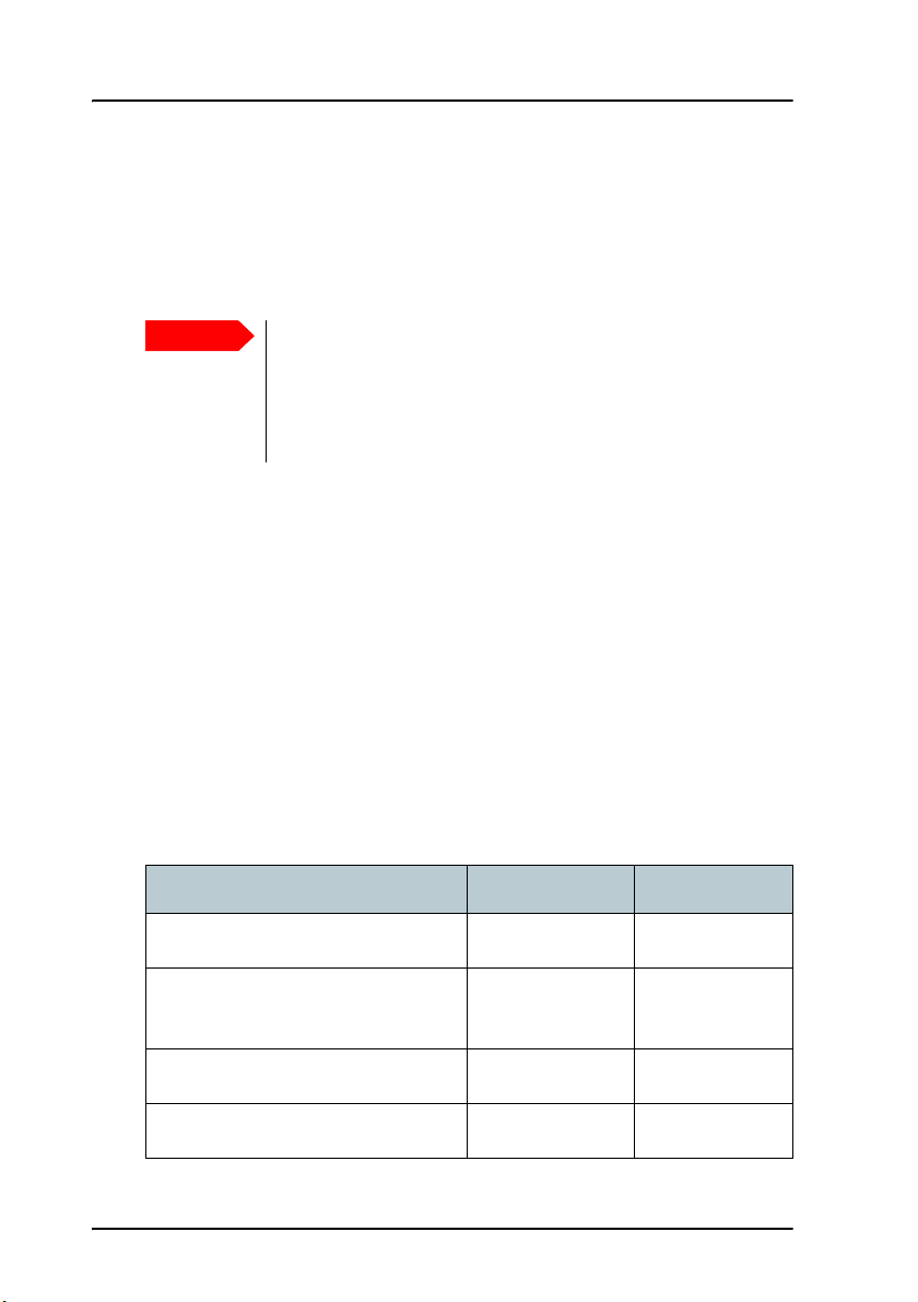
Power consumption
The total power consumption varies primarily due to system activities. Make
sure the backup battery is capable of providing the required power. As a
guideline, note the power consumption of the following equipment:
Unit Idle power Max. power
SAILOR 3027 GMDSS Terminal 1.85 W @15 V DC 30 W @15 V DC
SAILOR 6006 Message Terminal
(12 V DC - 24 V DC)
SAILOR 6101 Alarm Panel 1 W 2 W
SAILOR 6103 Multi Alarm Panel 1 W 4 W
14 General installation requirements
12 W 20 W
Chapter 3: Installing the system
Installing the system
Note
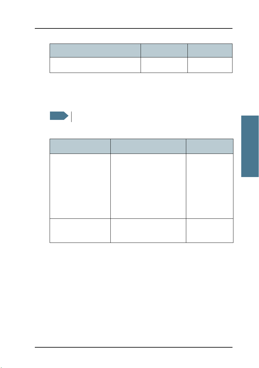
Unit Idle power Max. power
SAILOR 1252 Printer 3 W 30 W
Fuses
Before exchanging a fuse, check that the unit has not been damaged.
Only units with a replaceable fuse are listed in the table below.
The units in the SAILOR 6110 system have the following replaceable fuses:
Unit Location Fuse type
3333
SAILOR 6081
PSU and Charger.
SAILOR 1252 Printer Internally accessed, remove
AC input: Externally
accessed, next to Power
switch.
For other fuses, see the
Installation and User manual
for the SAILOR 6081 PSU and
Charger [4]
top cover
6.3 AT, 5x20 mm
6.3 AT, 5x20 mm
3.1.2 Grounding availability
Use a suitable location as close as possible to the SAILOR 6081 for connecting
the units to ship ground (hull).
General installation requirements 15
 Loading...