

Page 1
USER MANUAL
SAILOR
500/250 FleetBroadband
Page 2
22222
Chapter 2
Getting started 2
In this chapter
This chapter describes how to start up the system and make the first call or
data session.
For information on how to install the system, insert SIM card and connect
cables, refer to the installation manual for the SAILOR 500 FleetBroadband
and SAILOR 250 FleetBroadband systems.
Before you start
Operation at high temperatures
In very high ambient temperatures, do not touch areas of
the terminal that are marked with this symbol.
If the terminal is installed in a location where the ambient temperature may
rise above 50°C, we recommend placing the terminal where unintentional
contact is avoided. Note that the maximum allowed ambient temperature is
55° C.
Getting started
If the maximum ambient temperature does not exceed 50°C, the terminal can
be placed in a public area.
For further information on installation, refer to the installation manual for the
SAILOR FleetBroadband systems.
19
Page 3
Chapter 2: Getting started
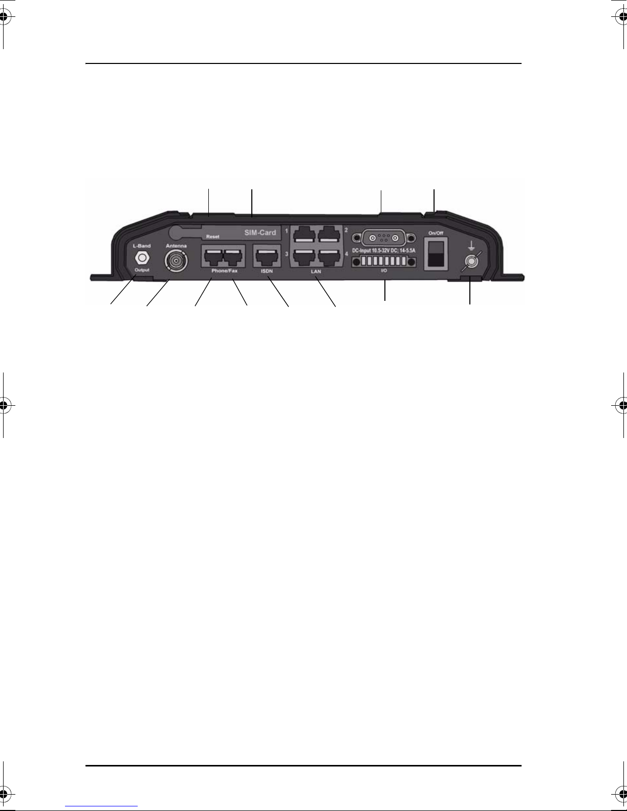
Connector panel
The drawing below shows the connector panel of the terminal.
Reset button
SIM slot
DC input
Power
switch
L-Band ISDNPhone/Fax 1Antenna
For information on how to connect to each interface, refer to the installation
manual for the SAILOR 500 FleetBroadband and SAILOR 250 FleetBroadband
systems.
Phone/Fax 2
4 x LAN w. PoE
I/O
Grounding stud
20 Before you start
Page 4

Starting up the terminal
SIM card
Note that the SAILOR FleetBroadband terminal requires a SIM card dedicated
to FleetBroadband. The terminal can only access the BGAN network when the
right type of SIM card is installed. For information on how to insert the SIM
card, refer to the installation manual.
22222
Chapter 2: Getting started
Getting started
Starting up the terminal 21
Page 5

Chapter 2: Getting started
Switching on the terminal
Using the Power switch
To switch on the terminal, use the Power switch in the connector panel. It
normally takes one or two seconds for the terminal to switch on.
Using the ignition system
Normally the ignition function is not used in maritime installations. Instead
you may want to use the remote on/off function described in the next section.
If you have connected the ignition system of your vessel to the I/O connector,
you may leave the power switch in the “on” position and the terminal will
switch on/off when you start/stop the engine of your vessel. When the engine
is stopped the terminal is in standby mode, meaning that only the primary
parts of the system are kept alive. The standby current is max. 15 mA when the
ignition is off. For information on how to connect to the I/O connector, refer to
the installation manual for the SAILOR 500 FleetBroadband system.
You must set up the ignition function in the web interface. For further
information, see Configuring the I/O interface on page 110.
Using a remote on/off switch
If a switch is connected to the remote on/off pins in the DC connector, you may
leave the power switch in the “on” position and use the remote switch to turn
the terminal on and off. When the remote switch is off, the terminal is off.
However, if you leave the power switch on the terminal in the “on” position,
22 Starting up the terminal
Page 6

you can always switch the terminal back on with the remote switch. The
standby current when the remote switch is off is max. 2 mA. For further
information on the remote on/off function, refer to the installation manual for
the SAILOR FleetBroadband systems.
Power up completed
When the terminal is switched on, the Power indicator in the LED panel of the
terminal lights green.
22222
Chapter 2: Getting started
Getting started
You can now access the terminal settings, but the terminal is not ready for
making calls or running data sessions until the system is registered on the
BGAN network. This normally requires that you enter a SIM PIN. For further
information, see Entering the SIM PIN for the terminal on page 26 and
Registering on the BGAN network on page 30.
To switch off the terminal tip the Power switch back. It takes 5 to 10 seconds to
power down the terminal. Alternatively use the ignition or remote on/off
function described above.
Starting up the terminal 23
Page 7

Chapter 2: Getting started
Connecting the IP handset
Power supply
The Thrane & Thrane IP handset is powered from the LAN interface, using
Power over Ethernet.
Starting up the IP handset
The following procedure is for the Thrane & Thrane IP handset. The procedure
may be different for another type of IP handset.
Note
Do as follows:
1. Connect the Thrane & Thrane IP handset to one of the LAN (PoE)
connectors on the terminal as described in the user manual for the
handset.
The handset starts up automatically.
2. If your SIM card requires a PIN and the PIN has not yet been entered in
the terminal, you can enter the PIN from the BGAN menu of the IP
handset.
To enter the PIN, select BGAN > Enter PIN from the handset menu system.
Note that this menu item is only available if the terminal is waiting for a
PIN. Then type in the Administrator user name and password followed by
the PIN for the terminal.
The first handset that is connected to the LAN interface on the
terminal is automatically registered in the terminal and assigned the
local number 0501 and password 0501. For information on how to
connect additional handsets, see Connecting a new IP handset on
page 105.
For further information on the IP handset, refer to the user manual for the
handset.
24 Connecting the IP handset
Page 8

Connecting a computer
Before connecting to the LAN interface
For the LAN interface to work without any further setup, the connected
computer must be set up to obtain an IP address and a DNS server address
automatically.
22222
Chapter 2: Getting started
Connecting a computer to the LAN interface
Do as follows:
1. Power up your computer.
2. Connect your LAN cable between the network connector on your computer
and one of the LAN connectors on the terminal.
3. When the computer and the terminal are ready, check the connection e.g.
by accessing the built-in web interface of the terminal with your browser.
For further information, see Accessing the web interface on page 60.
You may have to disable the Proxy server settings in your browser. For
further information, see Browser settings on page 58.
For information on how to configure the LAN interface on the terminal, see
Configuring the LAN interface on page 87.
Getting started
Connecting a computer 25
Page 9

Chapter 2: Getting started
Entering the SIM PIN for the terminal
Overview
Depending on your SIM card, you may have to enter a SIM PIN to use the
system. You can enter the PIN using a standard phone or ISDN phone, the IP
handset or the web interface.
For information on how to connect the IP handset or computer you are going
to use, see Connecting a computer to the LAN interface on page 25 or
Connecting the IP handset on page 24.
Entering the PIN using a phone or IP handset
To enter the PIN
If you have a phone connected to the terminal, you can use it to enter the PIN
at start up.
Do as follows:
Dial the PIN the same way you would dial a phone number:
• For an analog or ISDN phone:
Pick up the phone. When the terminal is waiting for a PIN, you will hear 2
beeps - pause - 2 beeps - etc.
Dial <PIN> followed by #.
When you hear a “busy” tone or a dialing tone, the PIN has been accepted
and you can hang up or dial a number.
• For an IP handset:
Select the BGAN menu, select Enter PIN and enter the user name and
password for the terminal. Then enter the PIN for the terminal.
Note that the menu item “Enter PIN” is only available if the terminal is
waiting for a PIN.
26 Entering the SIM PIN for the terminal
Page 10

Wrong PIN
Analog phone or ISDN phone: If, instead of the busy tone or dialing tone, you
continue to hear 2 beeps - pause - 2 beeps - etc., it means the PIN was not
accepted. Check that you have the correct PIN and try again.
If a wrong PIN has been entered three times, you will hear 3 beeps - pause - 3
beeps - etc. This means you have to enter the PUK (PIN Unblocking Key)
provided with your SIM card.
After entering the PUK, you must enter a new PIN of your own choice (4 to 8
digits long).
Dial the following:
22222
Chapter 2: Getting started
Getting started
<PUK> * <New PIN> * <New PIN> followed by # or off-hook key.
Example: If the PUK is 87654321 and the new PIN is 1234, dial
87654321 * 1234 * 1234 followed by # or off-hook key.
If you enter 10 wrong PUKs, the SIM card will no longer be functional. Contact
your Airtime Provider for a new SIM card.
IP handset: After having entered the user name and password for the terminal
you have 3 attempts to enter the SIM PIN, before you are asked to enter the
PUK (Pin Unblocking Key). The PUK is supplied with the SIM card for your
terminal.
Enter the PUK followed by a new PIN of your own choice. The PIN must be
from 4 to 8 digits long.
If you enter a wrong PUK 10 times, the SIM card will no longer be functional,
and you have to contact your Airtime Provider for a new SIM card.
Entering the SIM PIN for the terminal 27
Page 11

Chapter 2: Getting started
Entering the PIN using the web interface
To enter the PIN
Do as follows:
1. On a computer connected to the terminal, open your browser and enter
the IP address of the terminal. Refer to Using the web interface on page 57.
The default IP address is 192.168.0.1.
If your SIM card uses a PIN and the PIN has not yet been entered, the web
interface will open on the PIN page.
2. Type in the PIN and click OK.
When the PIN is accepted, the web interface opens the Dashboard and is
ready for use. If the PIN is not accepted, see the next section Wrong PIN.
28 Entering the SIM PIN for the terminal
Page 12

Wrong PIN
You have 3 attempts to enter the PIN in the web interface, before you are
asked to enter the PUK (Pin Unblocking Key). The PUK is supplied with your
SIM card.
Enter the PUK followed by a new PIN of your own choice. The PIN must be
from 4 to 8 digits long.
If you enter a wrong PUK 10 times, the SIM card will no longer be functional,
and you have to contact your Airtime Provider for a new SIM card.
22222
Chapter 2: Getting started
Getting started
Entering the SIM PIN for the terminal 29
Page 13

Chapter 2: Getting started
Registering on the BGAN network
Registration procedure
When the SIM PIN is accepted by the terminal, the SAILOR FleetBroadband
system starts the registration procedure on the BGAN network.
Note
You can monitor the registration procedure by looking at the Antenna and
Terminal indicators in the LED panel of the terminal.
Note that the registration procedure may take several minutes. The table on
the next page shows the normal sequence.
We recommend keeping the vessel on a steady course while the
antenna is performing a sky scan. If the vessel is turning during sky
scan, it increases the total duration of the sky scan process.
30 Registering on the BGAN network
Page 14

22222
Chapter 2: Getting started
LED indications during the registration procedure
This table shows how the startup procedure is signaled with the light
indicators. If an error occurs, the indicators will light yellow or red, depending
on the severity of the error.
Status Antenna indicator Terminal indicator
The antenna is starting up Flashing slowly green
The antenna is
performing a sky scan
Flashing rapidly green
Getting started
The terminal is
registering on the
network
The antenna is tracking. Steady green
The system is registered
and ready for use.
For further information on the indicators, see Light indicators on page 166.
Steady green Steady green
Flashing green
Registering on the BGAN network 31
Page 15

Chapter 2: Getting started
Making the first call
Introduction
When the Antenna and Terminal indicators in the LED panel on the terminal
both light steady green, you are ready to make or receive the first call.
The following sections provide a short guide to making calls. For more
detailed information, see Making or receiving a phone call on page 42.
Making a call from the terminal
To make a call from a phone or handset connected to the terminal, dial
00 <country code> <phone number> followed by # or off-hook key.
Example: To call Thrane & Thrane in Denmark (+45 39558800) from an
analog phone,
dial 00 45 39558800 #
Making a call to the terminal
Note
To make a call to a phone connected to the terminal, dial
+ <Mobile number>
• + is the prefix used in front of the country code for international calls.
By default all handsets connected to the terminal will ring on
incoming calls. If you have connected a fax, set the incoming call
type on that Phone/Fax interface to 3.1 kHz Audio to avoid that the
fax rings and answers an incoming Standard call. For further
information, see Selecting the call type on page 39.
32 Making the first call
Page 16

22222
Chapter 2: Getting started
• Mobile number: The mobile number of the terminal you are calling. The
first part of the number is always 870, which is the “country code” for the
BGAN system.
Note
Example: If you are calling from Denmark and the mobile number for 3.1 kHz
If the mobile numbers are listed in the web interface, you can look them up by
selecting PHONE BOOK > Mobile numbers.
If the numbers are not listed, refer to your airtime subscription. We
recommend using the web interface to save the mobile numbers for future
reference. See Viewing and editing the mobile numbers on page 75.
There are two Voice numbers, one for 3.1 kHz Audio and one for
Standard Voice.
Audio is 870782105234 on your terminal, and you want to make a
call to the terminal using 3.1 kHz Audio, dial 00 870 782105234.
Making a call from one terminal to another
To make a call from one terminal to another,
dial 00 <Mobile number>.
Getting started
What’s next?
After reading this chapter you should be able to start up the terminal and
make a simple data or voice connection.
The next chapters provide more information on the user interfaces and the
setup of the terminal. The following chapter, Operating the system, explains
how to use the system.
What’s next? 33
 Loading...