

Page 1

USER MANUAL
SAILOR 150 FleetBroadband
Page 2

SAILOR®150 FleetBroadband
Document number: 98-129217-A
Release date: June 9, 2009
Disclaimer
Any responsibility or liability for loss or damage in connection with the use of this product and the
accompanying documentation is disclaimed by Thrane & Thrane. The information in this manual is provided
for information purposes only, is subject to change without notice and may contain errors or inaccuracies.
Manuals issued by Thrane & Thrane are periodically revised and updated. Anyone relying on this information
should acquire the most current version, e.g. from Thrane & Thrane’s Extranet at: http://extranet.thrane.com.
Thrane & Thrane is not responsible for the content or accuracy of any translations or reproductions, in whole
or in part, of this manual from any other source.
Copyright © 2009 Thrane & Thrane A/S. All rights reserved.
Trademark acknowledgements:
• Thrane & Thrane is a registered trademark of Thrane & Thrane A/S in the European Union and the United
States.
• SAILOR is a registered trademark of Thrane & Thrane A/S in the European Union, the United States and
other countries.
• Windows and Outlook are registered trademarks of Microsoft Corporation in the United States and other
countries.
• Inmarsat is a registered trademark of International Maritime Satellite Organisation (IMSO) and is licensed
by IMSO to Inmarsat Limited and Inmarsat Ventures plc.
• Inmarsat’s product names are trademarks or registered trademarks of Inmarsat.
• Other product and company names mentioned in this manual may be trademarks or trade names of their
respective owners.
Company web site
www.thrane.com
98-129217-A ii
Page 3
Safety summary 1
MICROWAVE RADIATION
No personnel within safety distance
60
Safety distance:
(0.2 m, 100 W/m
2
)
0.6 m, 10 W/m
2
The following general safety precautions must be observed during all phases of operation, service and
repair of this equipment. Failure to comply with these precautions or with specific warnings elsewhere
in this manual violates safety standards of design, manufacture and intended use of the equipment.
Thrane & Thrane A/S assumes no liability for the customer's failure to comply with these requirements.
Observe marked areas
Under extreme heat conditions do not touch areas of the terminal or
antenna that are marked with this symbol, as it may result in injury.
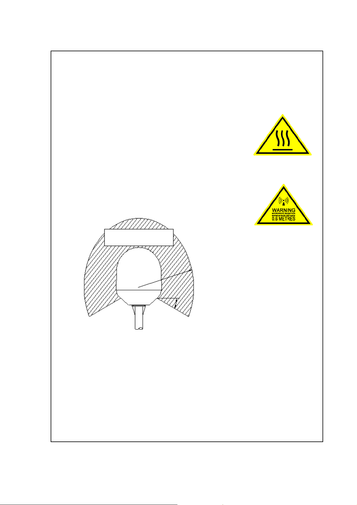
Microwave radiation hazards
During transmission the antenna in this system radiates Microwave
Power.This radiation may be hazardous to humans close to the antenna.
During transmission, make sure that nobody gets closer than the recommended minimum safety
distance.
On the SAILOR 150 FleetBroadband, the minimum safety distance to the
antenna panel on the focal line is 0.6 m, based on a radiation level of
10 W/m
antenna panel. Refer to the drawing below.
2
. The radiation level is 100 W/m2 at a distance of 0.2 m from the
Distance to other equipment
Do not move the antenna closer to radars than the minimum safe distance specified in the installation
manual - it may cause damage to the antenna. The equipment must be installed with the following
minimum safe distances to magnetic steering compass:
SAILOR 150 FleetBroadband Terminal: min. 0.3 m.
SAILOR 150 FleetBroadband antenna: min. 1.1 m
Service
User access to the interior of the system units is prohibited. Only a technician authorized by Thrane &
Thrane A/S may perform service - failure to comply with this rule will void the warranty. Access to the
interior of the antenna is allowed, but only for replacement of certain modules - as described in the
98-129217-A iii
Page 4

Installation manual. General service may only be performed by a technician authorized by Thrane &
Thrane A/S.
Do not service or adjust alone
Do not attempt internal service or adjustments unless another person, capable of rendering first aid
resuscitation, is present.
Grounding, cables and connections
To minimize shock hazard, the equipment chassis and cabinet must be connected to an electrical
ground. The terminal must be grounded to the ship. For further grounding information refer to the
Installation manual.
Do not extend the cables beyond the lengths specified for the equipment. The cable between the
terminal and antenna can be extended if it complies with the specified data concerning cable losses
etc.
All cables for the SAILOR FleetBroadband system are shielded and should not be affected by magnetic
fields. However, try to avoid running cables parallel to AC wiring as it might cause malfunction of the
equipment.
Power supply
The voltage range is 10.5 - 32 V DC; 14 A - 5.5 A. It is recommended that the voltage is provided by the
24 V DC bus on the ship. Be aware of high start-up peak current: 20 A@24 V, 5 ms.
If a 24 V DC power bus is not available, an external 115/230 VAC to 24 V DC power supply can be used.
Do not operate in an explosive atmosphere
Do not operate the equipment in the presence of flammable gases or fumes. Operation of any
electrical equipment in such an environment constitutes a definite safety hazard.
Keep away from live circuits
Operating personnel must not remove equipment covers. Component replacement and internal
adjustment must be made by qualified maintenance personnel. Do not replace components with the
power cable connected. Under certain conditions, dangerous voltages may exist even with the power
cable removed. To avoid injuries, always disconnect power and discharge circuits before touching
them.
Failure to comply with the rules above will void the warranty!
98-129217-A iv
Page 5

About the manual 2
Intended readers
This manual is a user manual for the SAILOR 150 FleetBroadband system. The readers of
the manual include anyone who is using or intends to use this system. No specific skills are
required to operate the SAILOR 150 FleetBroadband system. However, it is important that
you observe all safety requirements listed in the beginning of this manual, and operate the
system according to the guidelines in this manual.
Most current version
This manual may not always reflect the latest software functionality of your
SAILOR FleetBroadband system. To obtain the latest version of the manual, please enter the
Thrane & Thrane Extranet at: http://extranet.thrane.com and download the latest version,
or acquire it from your distributor.
Manual overview
Note that this manual does not cover installation nor does it cover how to use the IP
handset that comes with the system. For information on installation refer to the installation
manual and for information on the IP handset refer to the user manual for the IP handset.
Part numbers for both manuals are listed in the next section.
This manual has the following chapters:
• Introduction contains a brief description of the system and an overview of the BGAN
services.
• Getting started explains how to insert SIM (Subscriber Identity Module) card and start
up the unit. It also contains a short guide to making the first call.
• Operating the system explains how to use the system.
• Using the web interface explains how to use the built-in web interface of the terminal
for configuration and daily use, and describes the available menus and settings,
including advanced setup of interfaces.
• Trou bl es ho oting contains a short troubleshooting guide and explains how to update
software. It also describes the functions of the light indicator and the Reset button, and
explains the event messages that may show in the web interface. Further, it gives
information on where to get help if needed.
• Conformity contains declarations of conformity for the SAILOR 150 FleetBroadband
system.
98-129217-A v
Page 6

Related documents
The below list shows the documents related to this manual and to the
SAILOR 150 FleetBroadbandsystem.
Typo graphy
Title and description
SAILOR 150 FleetBroadband, Installation Manual
Explains how to install the SAILOR 150 FleetBroadband terminal and
the SAILOR 150 FleetBroadband antenna.
SAILOR 150 FleetBroadband, Quick Guide
A short guide to the most important functions of the
SAILOR 150 FleetBroadband system.
Thrane IP Handset, User Manual
Explains the features and functions of the Thrane IP Handset. The IP
handset works as a standard IP handset, but also serves as a user
interface for the SAILOR 150 FleetBroadband system.
In this manual, typography is used as indicated below:
Bold is used for the following purposes:
• To emphasize words.
Example: “Do not touch the antenna”.
Document
number
TT98-129218
TT98-129219
TT98-126059
• To indicate what the user should select in the user interface.
Example: “Select SETTINGS > LAN”.
Italic is used to emphasize the paragraph title in cross-references.
Example: “For further information, see Connecting Cables on page...”.
98-129217-A vi
Page 7

Safety summary ....................................................................................................iii
About the manual .................................................................................................. v
Chapter 1 Introduction
Welcome ...............................................................................................................1
In this chapter ..................................................................................................... 2
Features and interfaces ......................................................................................2
Main units ............................................................................................................ 3
The Inmarsat BGAN system ................................................................................ 7
Access to services and interfaces ......................................................................10
Chapter 2 Getting started
Table of Contents
In this chapter .................................................................................................... 11
Before you start .................................................................................................. 11
Starting up the terminal ....................................................................................12
Connecting the Thrane IP handset ....................................................................14
Connecting a computer ......................................................................................15
Entering the SIM PIN for the terminal ..............................................................16
Registering with the BGAN network .................................................................18
Making the first call ...........................................................................................19
Standard connection to the Internet (default) ................................................. 20
Chapter 3 Operating the system
In this chapter ....................................................................................................21
General ...............................................................................................................21
Using a phone ................................................................................................... 23
Using a computer .............................................................................................. 28
Using the IP handset ......................................................................................... 29
98-129217-A vii
Page 8

Chapter 4 Using the web interface
In this chapter ................................................................................................... 30
Introduction ....................................................................................................... 30
Entering the SIM PIN in the web interface ......................................................35
Using the Dashboard ........................................................................................ 36
Using the phone book ....................................................................................... 39
Using the Call log .............................................................................................. 42
Handling SMS messages .................................................................................. 44
Setting up the interfaces ...................................................................................50
Uploading software ........................................................................................... 79
Selecting the preferred BGAN satellite ............................................................ 82
Table of Contents
Selecting the language ..................................................................................... 83
Administration ................................................................................................... 84
Help desk and diagnostic report ...................................................................... 93
Event logging and self test ............................................................................... 94
Site map ............................................................................................................. 95
Chapter 5 Troubleshooting
In this chapter ................................................................................................... 96
Getting support ................................................................................................. 96
Uploading software ........................................................................................... 97
Part numbers ..................................................................................................... 98
Troubleshooting guide ......................................................................................99
Status signaling ................................................................................................102
Logging of events ............................................................................................. 110
Reset button ...................................................................................................... 111
Chapter 6 Conformity
Glossary
.............................................................................................................................114
Index .............................................................................................................................117
98-129217-A viii
Page 9
Chapter 1
Introduction 1
Welcome
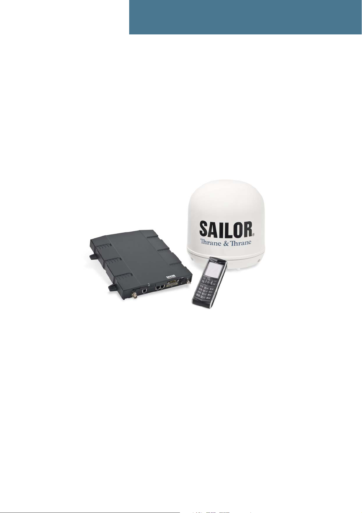
Congratulations on the purchase of your SAILOR 150 FleetBroadband system!
SAILOR 150 FleetBroadband is a maritime broadband system, providing simultaneous high-speed
data and voice communication via satellite through the BGAN (Broadband Global Area Network).
Applications include:
• Internet browsing
•E-mail
• Phone services
• Large file transfers
• VPN (Virtual Private Network) access to corporate servers
98-129217-A Welcome 1
Page 10

In this chapter
This chapter introduces the SAILOR 150 FleetBroadband system and gives an overview of the
physical units and their features and functions.
It also gives an overview of the BGAN system and services.
Features and interfaces
The SAILOR 150 FleetBroadband system offers the following features and interfaces:
Simultaneous voice and data communication over BGAN
Full duplex, single or multi-user, up to: 150 kbps
Standard Voice (4 kbps)
2 LAN (Local Area Network) ports with PoE (Power over Ethernet) for computers, e-hubs, IP
handset etc.
Chapter 1: Introduction
1 Standard Phone port for standard phone
1 multi-purpose I/O connector with 5 configurable inputs/outputs
1 SIM slot for your BGAN SIM card
Built-in DHCP/NAT router
Built-in web interface allowing you to manage your phone book, messages and calls, and
customize the terminal to your specific needs
Input power: 10.5 - 32 V DC (14 A - 5.5 A)
CE certified
98-129217-A In this chapter 2
Page 11

Main units
Units overview
The SAILOR 150 FleetBroadband system TT-3744A includes the following main units:
• TT-3050C SAILOR 150 FleetBroadband antenna
• TT-3739A SAILOR 150 FleetBroadband Terminal
•TT-3670A IP Handset & Cradle, wired
SAILOR®150 FleetBroadband antenna
The SAILOR 150 FleetBroadband system uses the TT-3050C antenna, which is a small size,
maritime BGAN antenna.
For information on how to install the antenna, refer to the installation manual.
Chapter 1: Introduction
98-129217-A Main units 3
Page 12
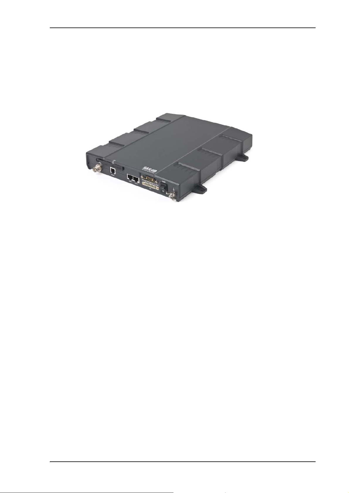
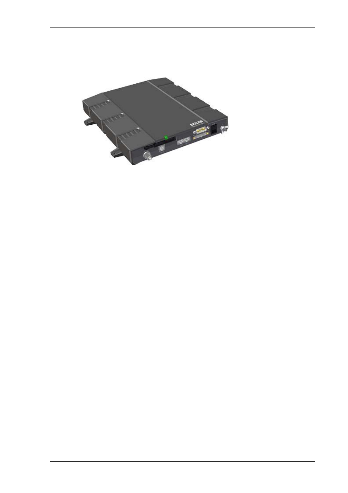
SAILOR®150 FleetBroadband terminal
Overview
The SAILOR 150 FleetBroadband Terminal is the controlling unit in the SAILOR 150 FleetBroadband
system. It contains all user interfaces and a LED indicator and stores configuration data.
Chapter 1: Introduction
Tools for setup and daily use
The Thrane IP Handset can be used for displaying status and for entering the PIN code for the
terminal. The IP handset connects to the LAN interface of the terminal. For information on how to
use the handset, see the user manual for the IP handset.
The built-in web interface in the terminal is used for easy configuration and daily use. The web
interface is accessed from a computer connected to the terminal, using an Internet browser. No
installation of software is needed.
For further information on the web interface, see Chapter 4, Using the web interface.
SIM card
The terminal has a SIM (Subscriber Identity Module) slot located in the connector panel behind a
small cover plate.
The terminal requires a dedicated FleetBroadband SIM card, which you get from your Airtime
Provider.
The system requires a SIM card to go online and to access the settings of the terminal. However,
using the web interface you can view the Dashboard and upload software without inserting a SIM
card. Upload of software without a SIM card requires an administrator user name and password
(default: “admin” and “1234”).
98-129217-A Main units 4
Page 13
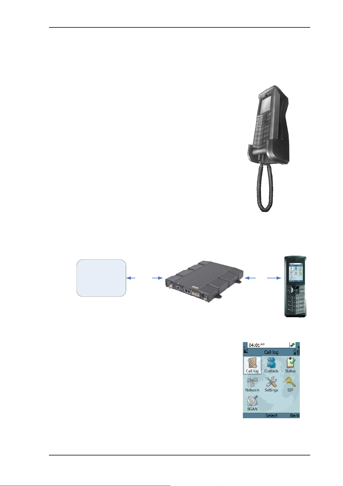
Thrane IP handset and cradle
IP data
Circuit
switched
connection
BGAN netwo rk
SAILOR 150 terminal
IP handset
The Thrane IP Handset communicates using Internet Protocols (IP).
The handset is not strictly dedicated to the
SAILOR 150 FleetBroadband system, but can also be used in a
public network as a standard IP telephone.
The IP handset is powered directly from the LAN interface using
Power over Ethernet (PoE).
Chapter 1: Introduction
When the IP handset is used with the terminal, it communicates using IP between the handset and
the terminal. However, on the BGAN network side of the terminal, calls are transmitted as circuitswitched calls.
When connected to the terminal the IP handset provides a
dedicated BGAN menu with a subset of the terminal configuration
options.
For more information on the functions of the IP handset, refer to the
user manual for the IP handset.
98-129217-A Main units 5
Page 14

IP cradle
Chapter 1: Introduction
The IP cradle serves as a holder for the IP handset.
The cradle connects to the coil cord from the handset and, using an Ethernet cable, to the
terminal. You can mount the cradle on a wall or a desktop.
98-129217-A Main units 6
Page 15

The Inmarsat BGAN system
Note
What is BGAN?
The Broadband Global Area Network (BGAN) is a mobile satellite service that offers high-speed
data and voice telephony. BGAN enables users to access e-mail, corporate networks and the
Internet, transfer files and make telephone calls.
The Inmarsat FleetBroadband service
FleetBroadband is a maritime communications service offered in the BGAN system. Based on 3G
standards, FleetBroadband provides cost-effective broadband data and voice simultaneously.
Coverage
The Inmarsat® BGAN services are based on geostationary satellites situated above the equator.
Each satellite covers a certain area (footprint). The coverage map below shows the footprints of the
BGAN system. For updated information on coverage, see Inmarsat’s home page at
www.inmarsat.com.
Chapter 1: Introduction
The map above shows Inmarsat’s expectations of coverage, but does not represent a
guarantee of service. The availability of service at the edge of coverage areas may
fluctuate.
98-129217-A The Inmarsat BGAN system 7
Page 16
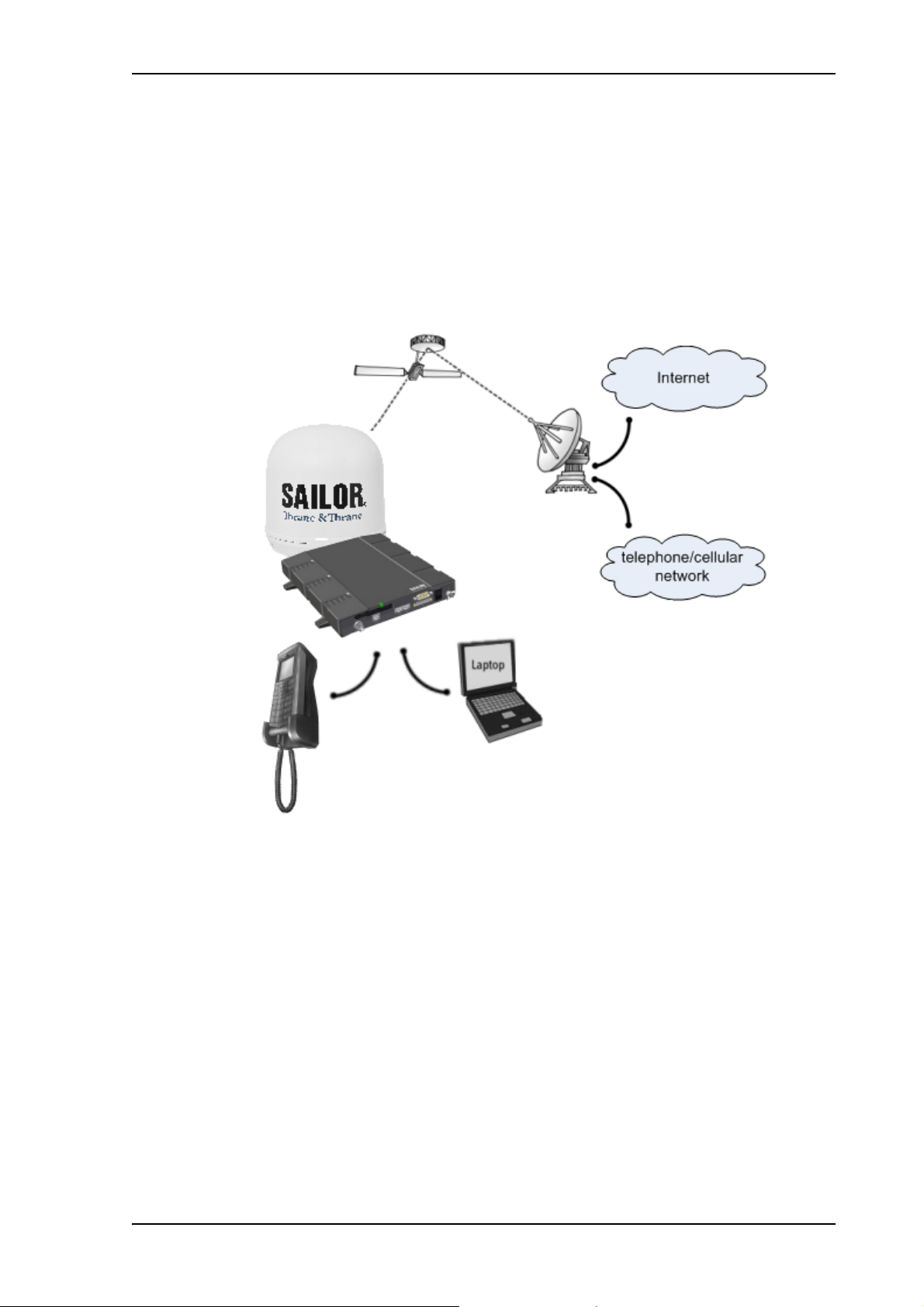
Overview of the BGAN FleetBroadband system
SAILOR 150
Satellite Access Station
(SAS)
Satellite
Packet-Switched Network
Circuit-Switched Network
SAILOR 150
FleetBroadband
FleetBroadband
IP Handset
antenna
terminal
A complete BGAN FleetBroadband system includes the SAILOR 150 FleetBroadband terminal with
connected peripherals, a SAILOR 150 FleetBroadband antenna, the BGAN satellite, and the
Satellite Access Station (SAS). The satellites are the connection between your terminal and the
SAS, which is the gateway to the worldwide networks (Internet, telephone network, cellular
network, etc.).
Chapter 1: Introduction
98-129217-A The Inmarsat BGAN system 8
Page 17

The BGAN services supported by SAILOR®150 FleetBroadband
Note
Note
Supported services
The BGAN services currently supported by the SAILOR 150 FleetBroadband comprise:
• A Packet-Switched (PS) connection to the Internet
• A Circuit-Switched (CS) dialed connection for voice
• Short Messaging Service (SMS)
Packet data service
The packet data service available for the SAILOR 150 FleetBroadband offers a Standard IP
(background) connection where several users can share the data connection simultaneously. This
type of connection is ideal for e-mail, file transfer, and Internet and intranet access. The user pays
for the amount of data sent and received.
Chapter 1: Introduction
The SAILOR 150 FleetBroadband only supports one PS connection to the Internet at a
time per SAILOR 150 FleetBroadband system.
Circuit-Switched (dialed) service
The circuit-switched service available for the SAILOR 150 FleetBroadband offers Standard Voice,
which is a low-tariff connection for voice only. The voice signal is compressed to 4 kbps, which
reduces the bandwidth use and consequently the tariff.
The BGAN system only supports one external CS call at a time per
SAILOR 150 FleetBroadband system.
SMS service
The BGAN system provides a Short Messaging Service (SMS) for sending and receiving SMS
messages to and from the terminal.
Supplementary services
The BGAN system also provides the following supplementary services:
• Call hold
• Call waiting
•Call forwarding
•Voice mail
• Call barring
98-129217-A The Inmarsat BGAN system 9
Page 18

Limitations
SIM lock
The supplier may have locked the SIM card to a specific provider. For further information, contact
your supplier.
Limitations in available services
The services available depend on your airtime subscription. Your SIM card may not allow for all
the services described in this manual.
Also, some services may not be available at the edge of coverage areas, i.e. in low elevations. For
further information on coverage, please refer to the Inmarsat home page at www.inmarsat.com.
Access to services and interfaces
The following table shows which equipment and interfaces you can use to access the services
listed in the left column.
Chapter 1: Introduction
Service
Circuit-Switched
(telephone)
Packet-Switched
(Internet, data
transfer etc.)
SMS
Interface on the terminal
Phone LAN (PoE)
Analog telephone IP handset
Computer
Computer with web
interface
98-129217-A Access to services and interfaces 10
Page 19
Chapter 2
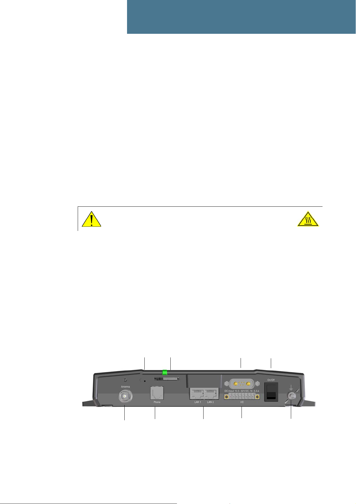
Grounding stud
Power
switch
I/O
DC input
2 x LAN w. PoE
Slot for SIM card
Antenna
Reset button
Phone
Getting started 2
In this chapter
This chapter describes how to start up the system and make the first call or data session.
For information on how to install the system, insert SIM card and connect cables, refer to the
installation manual for the SAILOR 150 FleetBroadband system.
Before you start
Operation at high temperatures
If the terminal is installed in a location where the ambient temperature may rise above 50C, we
recommend placing the terminal where unintentional contact is avoided. Note that the maximum
allowed ambient temperature is 55° C.
If the maximum ambient temperature does not exceed 50C, the terminal can be placed in a public
area.
For further information on installation, refer to the installation manual for the
SAILOR 150 FleetBroadband system.
Connector panel
The drawing below shows the connector panel of the SAILOR 150 FleetBroadband terminal.
CAUTION! In very high ambient temperatures, do not touch areas of the
terminal that are marked with this symbol.
98-129217-A In this chapter 11
Page 20
Starting up the terminal
SIM card
Note that the SAILOR 150 FleetBroadband terminal requires a SIM card dedicated to
FleetBroadband. The terminal can only access the BGAN network when the right type of SIM card
is installed. For information on how to insert the SIM card, refer to the installation manual.
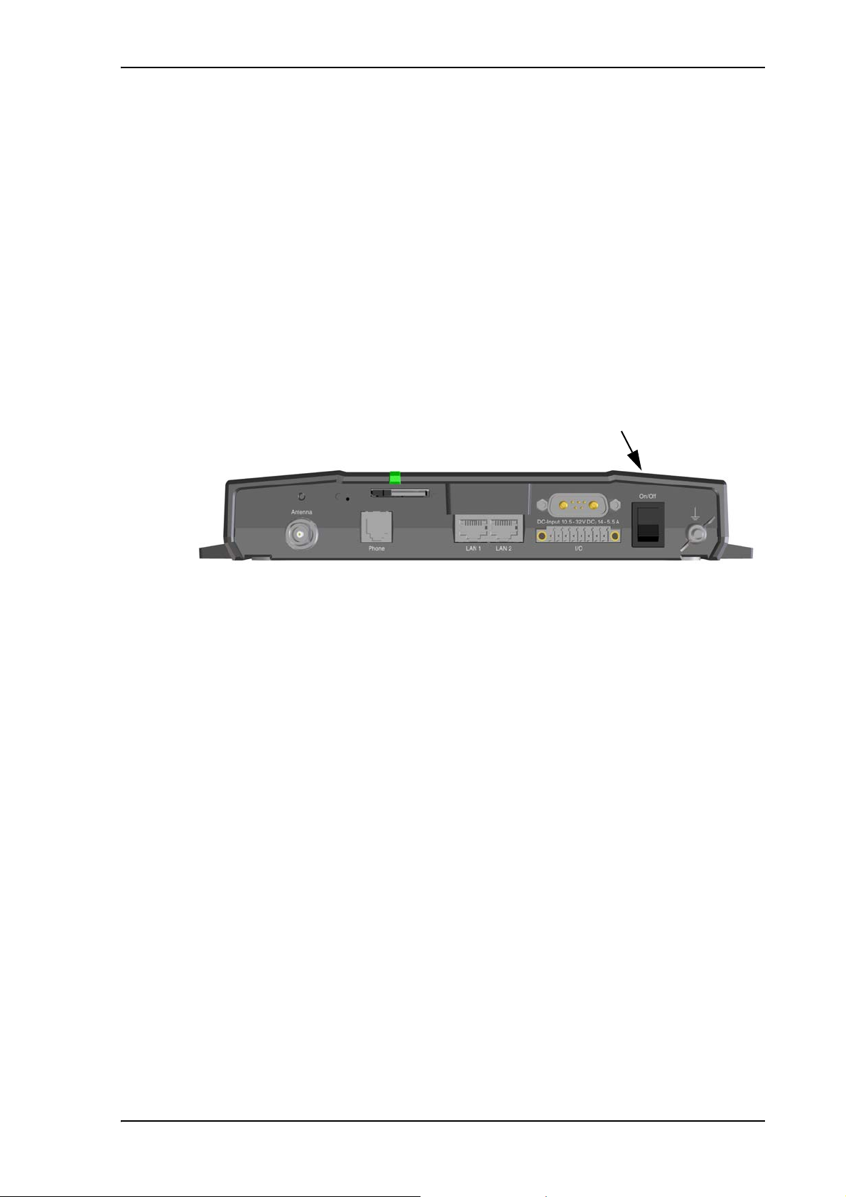
Switching on the terminal
Using the Power switch
To switch on the terminal, use the On/Off switch in the connector panel. It normally takes one or
two seconds for the terminal to switch on.
Chapter 2: Getting started
Using the ignition system
Normally the ignition function is not used in maritime installations. Instead you may want to use
the remote on/off function described in the next section.
If you have connected the ignition system of your vessel to the I/O connector, you may leave the
power switch in the “on” position and the terminal will switch on/off when you start/stop the
engine of your vessel.
When the engine is stopped the terminal is in standby mode. The standby current is max. 15 mA
when the ignition is off. For information on how to connect to the Ignition pins in the I/O
connector, refer to the installation manual for the SAILOR 150 FleetBroadband system.
You must set up the ignition function in the web interface. For further information, see Configuring
the I/O interface on page 78.
Using a remote on/off switch
If an external switch is connected to the remote on/off pins in the DC connector, you may leave the
power switch in the connector panel in the “on” position and use the remote switch to turn the
terminal on and off. When the remote switch is off, the terminal is off. However, if you leave the
power switch on the terminal in the “on” position, you can always switch the terminal back on
with the remote switch. The standby current when the remote switch is off is max. 2 mA. For
further information on the remote on/off function, refer to the installation manual for the
SAILOR 150 FleetBroadband system.
98-129217-A Starting up the terminal 12
Page 21
Power up completed
When the terminal is switched on, the Power indicator in the terminal lights green.
You can now access the terminal settings, but the terminal is not ready for making calls or running
data sessions until the system is registered on the BGAN network. You may have to enter a SIM
PIN before the system can register. For further information, see Entering the SIM PIN for the
terminal on page 16 and Registering with the BGAN network on page 18.
Chapter 2: Getting started
To switch off the terminal tip the Power switch back. It takes 5 to 10 seconds to power down the
terminal. Alternatively use the ignition or remote on/off function described above.
98-129217-A Starting up the terminal 13
Page 22

Connecting the Thrane IP handset
Note
Note
Power supply (PoE)
The Thrane IP Handset is powered from the LAN interface, using Power over Ethernet. The total
output power from the two interfaces is 32 W.
Both interfaces can support devices of power class 1, 2 and 3 (4, 7 and 15.4 Watt), as long as the
total power consumption does not exceed 32 W. If the limit is exceeded, the LAN ports are
prioritized so that LAN port 1 has the highest priority and port 2 is closed down. For this reason, we
recommend connecting your IP handset to LAN port 1.
In case of power hold-up (failure on input power), PoE will be turned off completely.
Starting up the Thrane IP Handset
The SAILOR 150 FleetBroadband only supports connection of one IP handset, which must
be the Thrane IP Handset.
Chapter 2: Getting started
To connect the Thrane IP Handset, do as follows:
1. Connect the Ethernet cable from the Thrane IP Handset/cradle to one of the LAN (PoE)
connectors on the terminal as described in the user manual for the handset.
We recommend connecting to LAN port 1, because port 2 will be closed down first in
case of insufficient power to the LAN (PoE) interface.
2. When the handset is connected to the LAN interface it is automatically registered in the
terminal and assigned the local number 0501 and password 0501.
3. The handset starts up automatically.
When the display shows this symbol in the upper right corner, the handset is ready for
making a call.
If the handset is not ready for making calls, it may be because the BGAN terminal is waiting for a
SIM PIN. To check this, enter the handset menu system and select BGAN > Status > PIN status.
You can enter the SIM PIN using the IP handset. For details, see Entering the SIM PIN using a
phone or IP handset on page 16.
98-129217-A Connecting the Thrane IP handset 14
Page 23

Connecting a computer
Before connecting to the LAN interface
For the LAN interface to work without any further setup, the connected computer must be set up to
obtain an IP address and a DNS server address automatically.
To check this on your computer (Windows XP), do as follows:
1. Go to Start > Settings > Control Panel > Network Connections.
2. Right-click on the LAN connection you want to use.
3. Select Properties, highlight Internet Protocol (TCP/IP).
4. Click Properties.
5. Make sure that the following is selected:
• Obtain an IP address automatically
• Obtain DNS server address automatically
Chapter 2: Getting started
Connecting a computer to the LAN interface
To connect a computer to the LAN interface, do as follows:
1. Power up your computer.
2. Connect your LAN cable between the network connector on your computer and one of the LAN
connectors on the terminal.
3. When the computer and the terminal are ready, check the connection e.g. by accessing the
built-in web interface of the terminal with your browser (enter the IP address, by default
http://192. 168.0.1, in the address bar of the browser). For further information, see Accessing
the web interface on page 32.
You may have to disable the Proxy server settings in your browser. For further information,
see Proxy settings when accessing the web interface on page 31.
For information on how to connect to the Internet, see Standard connection to the Internet
(default) on page 20.
For information on how to configure the LAN interface on the terminal, see Configuring the LAN
interface on page 51.
98-129217-A Connecting a computer 15
Page 24

Entering the SIM PIN for the terminal
Overview
Depending on your SIM card, you may have to enter a SIM PIN to use the system. Your SIM PIN is
supplied with your SIM card. You can enter the PIN using a standard phone, the IP handset or the
web interface.
For information on how to connect the IP handset or computer you are going to use, see
Connecting a computer to the LAN interface on page 15 or Connecting the Thrane IP handset on
page 14.
Entering the SIM PIN using a phone or IP handset
To enter the SIM PIN
If you have a phone connected to the terminal, you can use it to enter the SIM PIN for the terminal
at start up.
Chapter 2: Getting started
Do as follows:
• For an analog phone:
• For the Thrane IP Handset:
Wrong SIM PIN
Analog phone: If, instead of the busy tone or dialing tone, you continue to hear 2 beeps - pause -
2 beeps - etc., it means the SIM PIN was not accepted. Check that you have the correct PIN and try
again.
If a wrong PIN has been entered three times in the terminal, you will hear 3 beeps - pause - 3
beeps - etc. This means you have to enter the PUK (PIN Unblocking Key) provided with your SIM
card.
After entering the PUK, you must enter a new PIN of your own choice (4 to 8 digits long).
Pick up the phone. When the terminal is waiting for a PIN, you will hear 2 beeps - pause - 2
beeps - etc.
Dial <PIN> followed by #.
When you hear a “busy” tone or a dialing tone, the PIN has been accepted and you can hang
up or dial a number.
Select the BGAN menu, select Enter PIN and enter the administrator user name and password
for the terminal. Then enter the PIN for the terminal.
Note that the menu item “Enter PIN” is only available if the terminal is waiting for a PIN.
Dial the following:
<PUK> * <New PIN> * <New PIN> followed by # or off-hook key.
Example: If the PUK is 87654321 and the new PIN is 1234, dial
87654321 * 1234 * 1234 followed by # or off-hook key.
98-129217-A Entering the SIM PIN for the terminal 16
Page 25
If you enter 10 wrong PUKs, the SIM card will no longer be functional. Contact your Airtime
Provider for a new SIM card.
IP handset: After having entered the user name and password for the terminal you have 3 attempts
to enter the SIM PIN, before you are asked to enter the PUK (Pin Unblocking Key). The PUK is
supplied with the SIM card for your terminal.
Enter the PUK followed by a new PIN of your own choice. The PIN must be from 4 to 8 digits long.
If you enter a wrong PUK 10 times, the SIM card will no longer be functional, and you have to
contact your Airtime Provider for a new SIM card.
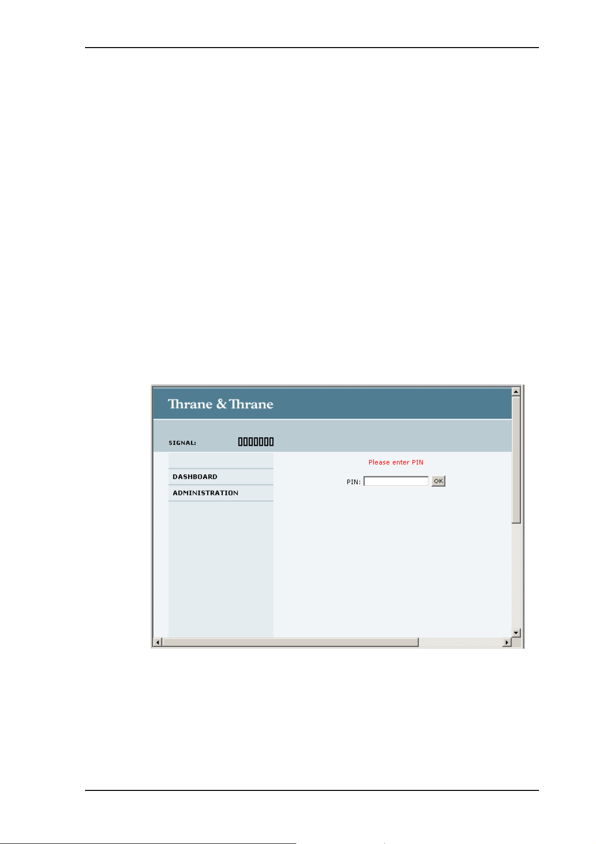
Entering the SIM PIN using the web interface
To enter the SIM PIN
Do as follows:
1. On a computer connected to the terminal, open your browser and enter the IP address of the
terminal.
The default IP address is 192.168.0.1.
If your SIM card uses a PIN and the PIN has not yet been entered, the web interface will open
on the PIN page.
Chapter 2: Getting started
2. Type in the PIN and click OK.
When the PIN is accepted, the web interface opens the Dashboard and is ready for use. If the
PIN is not accepted, see the next section Wrong PIN.
For further information on the web interface refer to Using the web interface on page 30.
98-129217-A Entering the SIM PIN for the terminal 17
Page 26

Wrong PIN
You have 3 attempts to enter the PIN in the web interface, before you are asked to enter the PUK
(Pin Unblocking Key). The PUK is supplied with your SIM card.
Enter the PUK followed by a new PIN of your own choice. The PIN must be from 4 to 8 digits long.
If you enter a wrong PUK 10 times, the SIM card will no longer be functional, and you have to
contact your Airtime Provider for a new SIM card.
Registering with the BGAN network
When the SIM PIN is accepted by the terminal, the SAILOR 150 FleetBroadband system
automatically starts the registration procedure on the BGAN network.
You can monitor the registration procedure in two ways.
• Connect the Thrane IP Handset and watch the procedure in the display.
• Connect a computer, access the internal web interface of the terminal and watch the Status
field in the DASHBOARD. For details, see Using the Dashboard on page 36.
Chapter 2: Getting started
The normal startup procedure is shown as follows:
1. Searching. The terminal has instructed the antenna to search for the BGAN signal.
2. Registering. The terminal is attempting to register with the Satellite Access Station (SAS).
3. Ready. The terminal has registered and attached to the SAS and is ready to accept a service
request (a call or a data session).
Note that the registration procedure may take several minutes.
98-129217-A Registering with the BGAN network 18
Page 27

Making the first call
Note
Introduction
When the terminal is registered with the BGAN network you are ready to make or receive the first
call.
The following sections provide a short guide to making calls. For more detailed information, see
Making or receiving a phone call on page 23.
Making a call from the terminal
To make a call from a phone or handset connected to the terminal, dial
00 <country code> <phone number> followed by # or off-hook key.
Example: To call Thrane & Thrane in Denmark (+45 39558800) from an analog phone,
dial 00 45 39558800 #
Chapter 2: Getting started
Making a call to the terminal
By default, any handset connected to the terminal will ring on incoming calls.
To make a call to a phone connected to the terminal, dial
+ <Mobile number>
• + is the prefix used in front of the country code for international calls.
• Mobile number: The mobile number of the terminal you are calling. The first part of the
number is always 870, which is the “country code” for the BGAN system.
Example: If you are calling from Denmark and the mobile number is 870772420567 on your
terminal, dial 00 870 772420567.
If the mobile number is listed in the web interface, you can look it up by selecting PHONE BOOK >
Mobile numbers.
If the number is not listed, refer to the documents provided with your airtime subscription. We
recommend using the web interface to save the mobile number for future reference. See Viewing
and editing the mobile number on page 41.
Making a call from one terminal to another
To make a call from one terminal to another, dial 00 <Mobile number>.
98-129217-A Making the first call 19
Page 28
Standard connection to the Internet (default)
Note
This section only describes a Standard Internet connection with default settings on the
terminal. For information on other scenarios, see Setting up the LAN network on page 54.
By default, the terminal does not automatically connect to the Internet when you connect your
computer or other equipment to the LAN interface. You must activate your connection from the
Dashboard in the web interface or from the Thrane IP Handset.
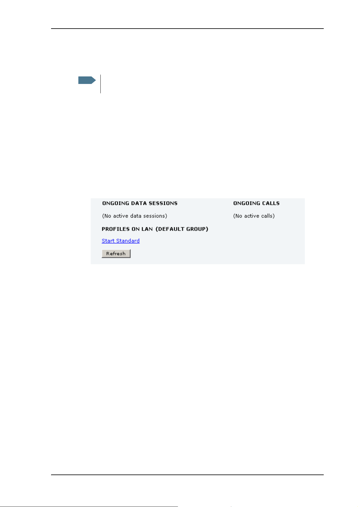
Activating the connection from a computer (web interface)
To activate the connection from a connected computer, do as follows:
1. Access the web interface by opening your browser and entering the IP address of the terminal
in the address bar (default IP address is 192.168.0.1).
2. Click Start Standard under PROFILES ON LAN at the bottom of the page.
Chapter 2: Getting started
3. Check the connection e.g. by entering a web site.
The field ONGOING DATA SESSIONS will show the IP address for the data session you started.
Activating the connection from the Thrane IP Handset
To activate the connection from the Thrane IP Handset, do as follows:
1. Connect the Thrane IP Handset to one of the LAN ports (preferably port 1).
The handset starts up automatically.
2. Select Menu > BGAN.
3. Select Connect.
4. Use the left/right keys to find the network user group for the application you want to start.
5. Press Start to start the connection.
A confirmation window is displayed.
6. Press Ye s to continue.
The Thrane IP Handset sends a command to the terminal to start the selected connection.
98-129217-A Standard connection to the Internet (default) 20
Page 29

Chapter 3
Operating the system 3
In this chapter
This chapter describes how to use the SAILOR 150 FleetBroadband system.
It does not describe advanced configuration of interfaces. For this type of information, refer to the
“Configuring...” sections for the interfaces in Chapter 4, Using the web interface.
General
Tools for setup and use
Overview
You can use the Thrane IP Handset for viewing status, using the phone book of the terminal and
for entering the PIN, but for enhanced use and for configuration of interfaces, you need to connect
a computer.
With a computer and a browser, you can use the built-in web interface to set up the terminal.
The IP handset
When you connect the Thrane IP Handset to one of the LAN (PoE) connectors on the terminal you
can use the handset display and keypad to enter the PIN or to view the status of the terminal.
The menu system in the IP handset includes the following items for the terminal:
•BGAN menu:
• Starting and stopping your data connection
• Viewing C/No (signal strength) for the system.
• Viewing status (“Ready”, “Registering” etc.) for the system.
• Viewing the software version of the terminal.
• Entering the PIN and PUK for the terminal.
• Viewing active events
•Viewing GPS status
•Contacts:
• Inclusion of the terminal phone book (not editable) in the IP handset Contacts.
• SIP (Session Initiation Protocol):
• Selecting/viewing the SIP profile used for communication with the BGAN terminal.
• Date and time:
98-129217-A In this chapter 21
Page 30

• Possibility of using UTC time received from the BGAN satellite.
For further information, see the user manual for the IP handset.
The web interface of the terminal
The web interface is a built-in web server for setting up and controlling the terminal, using a
connected computer with a browser. No installation of software is required.
With the web interface you can:
• Enter the SIM PIN for the terminal
•DASHBOARD page:
• start and stop data sessions
• view information on calls to/from the terminal
• view status of the terminal and antenna
• view properties of the terminal and antenna
•PHONE BOOK page:
• view and edit the phone book
Chapter 3: Operating the system
•MESSAGES page:
• send and receive SMS messages
•CALLS page:
• view the call log (outgoing, received and missed calls and data sessions)
• SETTINGS page:
• set up the interfaces of the terminal
• set up call services
• upload software
• set up network user groups (requires administrator password)
• select the satellite to use for connection to the BGAN network
• set the language in the web interface
• ADMINISTRATION page
• change the SIM PIN for the terminal
• set up user rights (requires administrator password)
For information on how to use the web interface, see Using the web interface on page 30.
98-129217-A General 22
Page 31

Using a phone
Available interfaces
Two types of voice equipment connect to the terminal:
Standard analog phone: The terminal has one phone connector for connecting a standard analog
phone.
IP handset: The terminal has two LAN connectors with Power over Ethernet for connecting the
Thrane IP handset. For information on the features and functions of the Thrane IP Handset, refer
to the user manual for the handset.
For information on how to connect to the interfaces, see the installation manual for the
SAILOR 150 FleetBroadband system.
Making or receiving a phone call
Chapter 3: Operating the system
Making a call
First connect your phone to the relevant interface. For further information, see the Installation
Manual.
You have different options for making a call:
• Short Dial. If the number is in the phone book of the terminal, you can use the Short Dial
• Manual Dial. To make a call, dial
• Call from phone book or call log (only IP handset).
number, which is found in the first column of the phone book in the web interface. See Short
dial on page 40.
Simply dial 00 <Short Dial> followed by # or off-hook key.
Example: To call entry number 4 in the phone book,
dial 004 followed by # or off-hook key.
00 <country code> <phone number> followed by # or off-hook key.
Example: To call Thrane & Thrane in Denmark (+45 39558800) from an analog phone, dial
00 45 39558800 #
• Enter the phone book of the IP handset, scroll to the wanted number and press the off-hook
key, or
• press the off-hook key from the main screen to display the latest calls in the call log. Then
scroll to the wanted number and press the off-hook key again.
Note that this is the call log of the IP handset, not of the terminal.
If there was an error establishing the connection, refer to the Troubleshooting Guide on page 99.
If you are using the IP handset, the handset may show an error message.
Depending on the type of error, the web interface may also show an error message. See Viewing
the Event list or the Event log on page 94.
98-129217-A Using a phone 23
Page 32

Receiving a call
To be able to receive a call, the phone must be connected to the relevant interface on the terminal.
By default, any handset connected to the Phone interface or the LAN (PoE) interface will ring when
the mobile number is called. Note, however, that Standard must be selected when setting up the
IP handset and the analog phone. Refer to Configuring the Phone interface on page 65 and
Enabling/Disabling incoming calls to a connected Thrane IP Handset on page 75
Call log
Information of missed calls is stored in the call log of the terminal. You can view the call log in the
web interface under CALLS. For further information, see Viewing the lists of calls and data sessions
on page 43.
Making a call to the terminal
To make a call to a phone connected to the terminal, dial
Chapter 3: Operating the system
+ <Mobile number>
• + is the prefix used in front of the country code for international calls.
• Mobile number. The first part of the mobile number is always 870, which is the “country code”
for the BGAN system. If the mobile number is listed in the web interface, you can look it up as
follows:
Connect a computer, access the web interface and select PHONE BOOK > Mobile numbers. For
further information, see Viewing and editing the mobile number on page 41.
If the mobile number is not available in the web interface, refer to your airtime subscription.
Receiving a voice mail message
If a call to the SAILOR FleetBroadband system is not answered the caller can leave a voice mail
message with Inmarsat’s voice mail service. Then an SMS is sent to the SAILOR FleetBroadband
messaging system to alert you that there is a voice message. The SMS has the contents:
• Number called from
• Date and time the voice mail message has been received
• Number to call to listen to the voice mail message
To see that a new SMS has arrived you open the web interface. For further details see Receiving a
message on page 46.
Making local phone calls
You can make local calls between phones connected to the terminal.
Local phone numbers always start with 0.
For an overview of the numbers assigned to each type of interface, see Local numbers and special-
purpose numbers on page 25.
To make a local call, dial <local number> followed by # or off-hook key.
98-129217-A Using a phone 24
Page 33

Dialing functions
Note
Local numbers and special-purpose numbers
There are a number of dialing functions available in the terminal. The following list shows the
allocated special-purpose numbers for the terminal.
Remember the “0” when you dial a local phone number. If you accidently dial a 3-digit
number, you may get one of Inmarsat’s short dial numbers.
Number Function
Chapter 3: Operating the system
0 * followed by # or off-hook
key
00 * followed by # or off-hook
key
00 followed by one of the
numbers 1-199 and # or offhook key
0301 followed by # or off-hook
key
0 501 followed by # or off-hook
key
Dialing prefixes
Apart from the numbers above, the terminal uses the following dialing prefixes:
Redial last called number on this
interface.
Redial last answered call on this
interface.
Note: If the last answered number is an
unlisted number, you will not be
allowed to dial back.
Short dial phone numbers in phone
book.
Local call to analog phone.
Local call to IP handset.
• #31# before the phone number will hide the caller’s phone number to the recipient.
• *31# before the phone number will show the caller’s phone number to the recipient where it
would otherwise be hidden, e.g. because the number is an ex-directory number.
• Use R during a call to get access to a supplementary services function. The supplementary
services functions supported by the terminal are described in the following sections.
98-129217-A Using a phone 25
Page 34

Handling waiting calls
Note
Note
The phone must have an R key to be able to use these functions.
During a call, if a second party tries to call you, you may hear a Call Waiting indication. The Call
Waiting indication is two beeps and a pause of 3 seconds, then two beeps again etc. If no action is
taken, the waiting call is released after a time-out period.
In the web interface you can enable or disable the call waiting indication. For further information,
see Call waiting on page 70.
When you receive a Call Waiting indication, you have the following options:
If you want to: Do as follows:
Chapter 3: Operating the system
Clear the current call,
Press R 1 #, within the time-out period.
and accept the waiting
call.
Hold the current call,
Press R 2 #, within the time-out period.
and accept the waiting
call.
Ignore the waiting call. Take no action.
Reject the waiting call. Press R 0 #, within the time-out period.
The BGAN system only supports one external call at a time.
98-129217-A Using a phone 26
Page 35

Holding a call
Note
Note
Note
Note
During a call, you may place the initial call on hold while another call is made.
If you want to: Do as follows:
Place a call on hold. Press R 2 #.
Chapter 3: Operating the system
The phone must have an R key to be able to use these functions.
Place the existing call on
hold and establish a new
call.
Shuttle between the two
calls.
Clear the held call, if no
waiting call exists.
Clear an active call and
return to the held call.
Transferring a call
Press R and dial the second phone
number followed by #.
Press R 2 #
(irrespective of whether the second call
was acquired using Call Hold or
acceptance of Call Waiting.)
Press R 0 #.
Press R 1 #.
Note that this is only possible if no
waiting call exists.
The BGAN system only supports one external call at a time.
The phone must have an R key to be able to use these functions.
When you receive a call, you can transfer this call to another phone connected to the terminal.
To transfer the incoming call to another phone or headset, do as follows:
1. Press R 4 * <local number> #.
The phone with the local number you dialed starts to ring.
2. You now have two options.
• Hang up. The phone or headset you transferred the call to continues to ring. When the call
is answered, a connection is established between the initial caller and the new recipient.
• Do not hang up. When the new recipient answers, you can have a conversation before
hanging up. When you hang up, the call is handed over to the initial caller.
The BGAN system only supports one external call at a time.
98-129217-A Using a phone 27
Page 36

Using a computer
Interfaces
The terminal has two LAN connectors for connecting computers, the Thrane IP Handset or other
LAN equipment.
For information on how to connect to the interfaces, see the installation manual for the
SAILOR 150 FleetBroadband system.
Chapter 3: Operating the system
Working with network user groups
Two network user groups are available to the users of the terminal:
• The Default group: By default, all users belong to the Default network user group, which
provides a shared Standard connection to the Internet using the built-in router functionality of
the terminal. This group does not allow Bridge mode.
• Group 0: A second group used for Bridge mode connection (Bridge mode is an exclusive
connection, with NAT disabled in the terminal). With Group 0 the Internet connection is
automatically established when the system is ready for transmission.
If you want to have a direct Bridge mode connection use this network user group.
For further details, see Setting up the LAN network on page 54.
Connecting to the Internet
Default setup
By default, any IP device that is connected to the terminal belongs to the Default network user
group. It uses a Standard shared IP connection, which you must manually activate from the web
interface. For further information on network user groups, see Setting up a Bridge mode
connection on page 57 and Setting up the Default network user group on page 55.
98-129217-A Using a computer 28
Page 37

Accessing your data sessions
Data sessions available for the current user are displayed under PROFILES ON LAN at the bottom of
the DASHBOARD.
• Profiles that are currently active are displayed as a link with the text “Stop <name of profile>”.
• Profiles ready to be activated are displayed as a link with the text “Start <name of profile>”.
Start/stop Standard IP on the LAN interface
Chapter 3: Operating the system
By default, Standard IP is not automatically activated on the terminal. If you want Standard IP to
be automatically activated at start-up, the administrator can enable automatic activation under
SETTINGS > LAN > Network user groups. For details, see Setting up the Default network user group
on page 55.
When automatic activation is disabled in the Network user groups page, you can manually
start/stop your Standard IP profile from the Dashboard by clicking Start <name of profile> or Stop
<name of profile> under PROFILES ON LAN at the bottom of the page.
Using the IP handset
You can use the Thrane IP Handset as user interface for the SAILOR 150 FleetBroadband system as
well as for making calls.
The IP handset has a dedicated menu for the SAILOR 150 FleetBroadband system. You find a list of
the menu items available in The IP handset on page 21.
For information on how to start up the IP handset, see Connecting the Thrane IP handset on
page 14.
For further information on how to use the IP handset, refer to the IP Handset User Manual.
98-129217-A Using the IP handset 29
Page 38

Chapter 4
Using the web interface 4
In this chapter
This chapter describes how to use the web interface to operate, set up and configure your
SAILOR 150 FleetBroadband system.
Introduction
The web interface
What is the web interface?
The web interface is built into the terminal and is used for operating, setting up and configuring
the system.
You can access the web interface from a computer with a standard Internet browser.
98-129217-A In this chapter 30
Page 39

Proxy settings when accessing the web interface
Note
If you are connecting your computer using a LAN or WLAN interface, the Proxy server settings in
your browser must be disabled before accessing the web interface. Most browsers support
disabling of the Proxy server settings for one specific IP address, so you can disable Proxy server
settings for the web interface only, if you wish. Consult your browser help for information.
To disable the use of a Proxy server completely, do as follows:
The following description is for Microsoft Internet Explorer. If
you are using a different browser, the procedure may be
different.
1. In Microsoft Internet Explorer, select Tools > Internet Options > Connections > LAN Settings.
Chapter 4: Using the web interface
2. Clear the box labeled Use a proxy server for your LAN.
3. Click OK.
When the proxy server settings are disabled, close your browser.
You may need to change this setting back on return to your Internet connection.
98-129217-A Introduction 31
Page 40

Accessing and navigating the web interface
Note
Accessing the web interface
To access the web interface, do as follows:
1. Connect your computer to the terminal.
2. Start up the terminal.
For details, see Getting started on page 11.
3. Open your browser and enter the IP address of the terminal.
The default IP address is http://192.168.0.1.
If the IP address is changed and you do not have the new address, you can temporarily
set the IP address to the default value by pressing the Reset button next to the SIM slot in
the connector panel of the terminal. You can then access the web interface and change
the IP address.
Note that if you do not change the IP address, the default IP address will only be valid
until the terminal is powered off. Then the terminal returns to the IP address from before
the Reset button was pressed.
Chapter 4: Using the web interface
For further information on the Reset button, see Reset button on page 111.
Changing the language
When you have access to the web interface, if you want to display a different language than
English, select SETTINGS > LANGUAGE from the left menu, select a language from the list and click
Apply. For further information, see Selecting the language on page 83.
98-129217-A Introduction 32
Page 41

Overview of the web interface
Navigation
Status
Icon bar Contents section
pane
field
Title bar
When the web interface opens, the title bar shows the name of the product.
The web interface consists of the following sections.
Chapter 4: Using the web interface
•The navigation pane holds the main menu. Clicking an item in the menu opens a submenu in
the navigation pane or a new page in the contents section.
•The status field shows the signal strength.
•The icon bar shows icons for new SMS messages and for active events, when relevant. For
explanations of the icons, see the next section, Icons in the icon bar.
•The contents section shows the page selected in the navigation pane. This section is used for
viewing or changing settings, or for performing actions.
98-129217-A Introduction 33
Page 42

Icons in the icon bar
The following icons may appear in the icon bar in the web interface:
Icon Explanation
Chapter 4: Using the web interface
A new SMS message, or information of Voice mail, has
arrived.
Click the icon to see new messages or information of Voice
mail. For further information, see Receiving a message on
page 46.
An event is active.
Click the icon to see a list of active events. For explanations
of the event messages, see List of events on page 103.
Note that this icon will remain in the icon bar as long as the
event is still active.
Navigating the web interface
• To expand a menu, click the menu in the navigation pane.
• To access status and settings, click the relevant subject in the navigation pane or click the
relevant icon in the icon bar. The status or settings are displayed in the contents section.
• To see the site map, click SITE MAP in the navigation pane. The site map lists all topics and
submenus. Click on items in the site map to go directly to the relevant location.
98-129217-A Introduction 34
Page 43

Entering the SIM PIN in the web interface
Note
Note
Do you need a SIM PIN?
You may not have to enter a SIM PIN to access the terminal. This depends on whether or
not the use of a SIM PIN is enabled on your SIM card.
The administrator can enable and disable the use of a SIM PIN. For details, see Setting
up the use of SIM PIN in the terminal on page 89.
If a computer is connected when you start up the terminal, you can access the web interface and
enter the SIM PIN here.
If your SIM card requires a PIN, and the PIN has not yet been entered, you must enter it. When you
access the web interface, it opens on the PIN page. Until you have entered the PIN you can only
upload software and view the DASHBOARD. Access to all other parts of the web interface requires
a PIN.
For information on how to enter the SIM PIN, see Entering the SIM PIN using the web interface on
page 17.
Chapter 4: Using the web interface
When the correct PIN has been entered, the web interface opens the Dashboard and is ready for
use.
Some parts of the web interface may be greyed out if the user permissions are limited.
For information on how to set up user permissions, see Setting up user permissions on
page 91.
98-129217-A Entering the SIM PIN in the web interface 35
Page 44

Using the Dashboard
Overview
The Dashboard is used for control and inspection of ongoing communication and for viewing
properties and status of the terminal and antenna.
For information on how to start or stop your data sessions from the Dashboard, see Connecting to
the Internet on page 28.
Chapter 4: Using the web interface
98-129217-A Using the Dashboard 36
Page 45

Properties
Note
The PROPERTIES section of the DASHBOARD shows the following information:
• Airtime provider. The name of your Airtime Provider.
• GPS position. The GPS position of your SAILOR 150 FleetBroadband system.
• Status. The status of the SAILOR 150 FleetBroadband system.
Chapter 4: Using the web interface
In some cases, the BGAN network does not allow the position to be displayed to the
user. If this is the case, the display may just show GPS acquired. This means that the
GPS position is received, but not shown.
This also applies if the SAILOR FleetBroadband is not yet registered on the BGAN
network, but the GPS position is received.
The status can be one of the following:
• Searching. The terminal has instructed the antenna to search for the BGAN signal. (The
antenna status will show “Sky scan”)
• Registering. The terminal is attempting to register with the Satellite Access Station (SAS).
• Ready. The terminal has registered and attached to the SAS and is ready to accept a service
request (a call or a data session).
• Data active. The terminal has established a call or a data session through the BGAN
network.
• No GPS fix. The GPS receiver has not yet achieved position fix. It may take some time to
achieve GPS fix depending on a number of conditions. First of all, the antenna should have
an unblocked view to as much of the sky as possible.
The terminal will not be able to register with the SAS without a GPS fix.
• Not registered. The terminal has not been able to register with the BGAN network.
• Satellite selection. The satellite selected for logon. For further information, see Selecting the
preferred BGAN satellite on page 82.
• Current satellite. The satellite to which the system is currently logged on.
• Unit serial number. The serial number of the terminal.
• Software version. The version of the software embedded in the terminal.
• Local IP address. The local IP address of the terminal. This is the IP address used to access the
terminal from a device connected to the terminal.
• IMEI number. The IMEI number (International Mobile Equipment Identity) of the terminal. This
is a unique number that identifies your terminal.
• Antenna status. The status of the antenna.
The antenna status can be:
• Sky scan. The antenna is searching for the BGAN signal.
• Tra ckin g. The antenna has found and locked to the BGAN signal. The antenna is now
tracking the BGAN signal.
98-129217-A Using the Dashboard 37
Page 46

Viewing information on calls and data sessions
Note
Note
The following sections in the Dashboard show information on calls and data sessions.
The counters for calls and data sessions are only intended as a guide and cannot be used
for direct comparison with your airtime bill.
• ONGOING CALLS is a list of calls that are currently active. The list shows the call type and the
time connected for each call.
• ONGOING DATA SESSIONS is a list of data profiles that are currently active, including the IP
address that is assigned to each profile.
• SESSIONS TOTAL lists the totals for each connection. The list shows the time connected
(hh:mm:ss) for voice, and MB transferred for Standard data.
The counters show totals for connections since the counters were last cleared. For information on
how to clear the counters, see Log handling on page 88.
If power to the terminal is interrupted unintentionally, the totals may be slightly
inaccurate at next startup.
Chapter 4: Using the web interface
98-129217-A Using the Dashboard 38
Page 47

Using the phone book
General usage
Overview
In the phone book you can:
• Look up phone numbers.
• Look up short-dial numbers for easy dialing from a handset.
• Modify or delete existing names and phone numbers, or add new names and phone numbers.
Accessing the phone book
To access the phone book, select PHONE BOOK from the left navigation pane.
Chapter 4: Using the web interface
98-129217-A Using the phone book 39
Page 48

Short dial
Chapter 4: Using the web interface
The phone book shows all entries with entry number, name and phone number. Empty place
holders are also included.
To sort the phone book, click the title of the column you wish to sort by. For example, to sort by the
names in the phone book alphabetically, click on Name in the top row of the phone book.
The phone book holds 199 entries divided into subpages. To select the subpages you want, click
the relevant link at the bottom of the page.
The entry number in the phone book is the Short dial number. When making a call from the
terminal you can use this number instead of dialing the entire phone number.
Simply dial 00 <short dial> followed by # or off-hook key.
Example: To call the third entry in the phone book from an analog phone, take the phone off hook
and dial 003 #.
Editing phone book entries
Adding a new entry
To add a new entry, do as follows:
1. In the phone book, locate the empty entry number where you want to add the new phone
number and click New.
2. Type in the name and phone number of the new entry and click Save entry.
The new name and number are now listed at the specified entry number in the phone book.
Modifying an entry in the phone book
To modify an entry, do as follows:
1. In the phone book, click Edit next to the entry you want to modify.
2. Modify the name or number as wanted and click Save entry.
The name and/or number in the selected entry is now replaced with the new information.
Deleting an entry in the phone book
To delete an entry, click Delete next to the entry you want to delete.
Deleting all entries in the phone book
To delete all the entries in the phone book, click Delete all entries in phone book at the bottom of
the PHONE BOOK page.
98-129217-A Using the phone book 40
Page 49

Viewing and editing the mobile number
Note
The mobile number is the phone number to use when making a call to the terminal.
To view the mobile number
To view the mobile number of the terminal, select PHONE BOOK > Mobile numbers from the left
navigation pane.
This number is not listed at delivery. The user must enter the number received from the
Airtime Provider.
Chapter 4: Using the web interface
To enter or edit the mobile number
To enter or edit the mobile number, click Edit at the bottom of the page, type in the number
received from your Airtime Provider and click OK.
98-129217-A Using the phone book 41
Page 50

Using the Call log
Information on total usage
To enter the CALLS page select CALLS from the left navigation pane. This page contains
information on usage for circuit-switched connections.
Chapter 4: Using the web interface
98-129217-A Using the Call log 42
Page 51

Exporting the call log
Note
You can export the call log file and save it on your computer for archiving, surveillance or other
tracking purposes.
The call log holds information on all calls and data sessions since the call log was last cleared. For
information on how to view the lists of calls and data sessions, see the next section.
To export the entire call log to a file, do as follows:
1. In the CALLS page, click the link Export call log to file.
2. Browse to the location where you want to save the log.
3. Click OK.
Viewing the lists of calls and data sessions
To see information on outgoing, received or missed calls or data sessions, select one of the
following lists from the left navigation pane in the CALLS page:
Chapter 4: Using the web interface
• Outgoing calls shows the start time, receiving end phone number, duration, type and
estimated charge of each outgoing call.
• Received calls shows the start time, calling phone number, duration and type of each incoming
call.
• Missed calls shows the start time, calling phone number and type of each incoming call that
was not received.
• Standard data sessions shows the start time, bytes in, bytes out and estimated charge of each
Standard IP session.
Date and time is the international UTC time, received from the satellite.
For information on the available types of service, see The BGAN services supported by
SAILOR
You can sort each of the lists by clicking the title of the column you wish to sort by.
If a list covers more than one page, you can click the relevant link at the bottom of the page, to go
to another page.
When there are more than 100 calls in the total list, the oldest calls are automatically removed to
make room for new calls.
150 FleetBroadband on page 9.
®
The estimated charge is based on your entries under ADMINISTRATION > Call charges.
Thrane & Thrane does not take responsibility for the correctness of this estimated charge.
98-129217-A Using the Call log 43
Page 52

Handling SMS messages
Important
Sending an SMS message
If the terminal is not online when you attempt to send a message, the message is
moved to the Outbox instead of the Sent folder. Messages in the Outbox are not
automatically sent when the terminal goes online. For further information on the
Outbox, see the next section, Options for messages in the Outbox.
To make sure a message has been sent, check that it has been moved to the Sent
folder.
To send an SMS message from the terminal, do as follows:
1. Click MESSAGES from the left navigation pane.
This page contains new incoming messages.
2. In the left navigation pane, click Write message.
Chapter 4: Using the web interface
3. Type in the message in the Write new message field.
If the message text is too long for one SMS, the message is sent as two or more SMS
messages. The field below the message field shows the number of SMS messages used to
send the message.
4. Type in the phone number in the Recipient field.
Remember 00 and country code (e.g. 00 45 for Denmark or 00 1 for USA).
98-129217-A Handling SMS messages 44
Page 53

5. Select whether or not you want Delivery notification for this SMS message.
If you click Yes, the Status column in the Sent folder will show the status of your message
when it has been sent.
You can set up delivery notification generally for all SMS messages. This setting is used by
default when you send a message. For further information, see Configuring message settings
on page 48.
6. Click Send.
The message is now sent and moved to the Sent folder.
Options for messages in the Outbox
Messages in the Outbox are messages that have not been sent, e.g. because the terminal was not
online when you attempted to send the messages.
To access the Outbox, click MESSAGES > Outbox from the navigation pane.
You have the following options for messages in the Outbox:
• When the terminal is online, click Resend next to the message you want to send. When the
Write message page opens, click Send.
The terminal now attempts to send the message again. To make sure the message has been
sent, look in the Sent folder.
Chapter 4: Using the web interface
• Click Delete next to a message to delete it.
• Click Delete all messages in Outbox to delete all the messages.
Options for messages in the Sent folder
The Sent folder contains SMS messages that have been sent.
To access the Sent folder, select MESSAGES > Sent from the navigation pane.
The Status column shows the status of each message, if you have selected Delivery notification
when sending the message.
From the Sent folder you have the following options:
• Click Resend next to a message you want to send again.
When the Write message page opens, click Send.
The terminal now attempts to send the message again. To make sure the message has been
sent, look in the Sent folder. There should now be two copies of the sent message.
• Click Forward next to a message you want to forward.
Type in the phone number of the new recipient and click Send.
The terminal now attempts to send the message to the new recipient. To make sure the
message has been sent, look in the Sent folder.
• Click Delete next to a message to delete it.
• Click Delete all sent messages to delete all the messages.
98-129217-A Handling SMS messages 45
Page 54

Sending an SMS message to the terminal
Note
You can send an SMS message to the terminal e.g. from a mobile phone, using the mobile number
for the terminal. Dial
+ <Mobile number>
The first part of the mobile number is always 870, which is the “country code” for the BGAN system.
If the mobile number is listed in the web interface, you can look it up as follows:
Select PHONE BOOK > Mobile numbers. If the mobile number is not listed in the web interface,
refer to the documents provided with your airtime subscription.
Receiving a message
If a message has arrived, the icon bar at the top of the web interface shows an unopened
envelope. Click the envelope to see the new message(s).
Otherwise, to see new messages click MESSAGES from the left navigation pane.
The page shows new incoming messages.
Chapter 4: Using the web interface
The terminal does not accept more than 100 incoming messages (including read and
unread messages). If you have received 100 messages, you have to delete some of them
in order to free space for new messages. Otherwise, the new messages are rejected.
If the message is not an SMS message but information of voice mail, call your Voice mail service
number to hear the Voice mail. The Voice mail service number is normally listed in the SMS
message.
You may also find the Voice mail service number under MESSAGES > Message settings. Note that
the voice mail number is only shown here if it is available on the SIM card. Otherwise, refer to the
information included with your Airtime subscription.
98-129217-A Handling SMS messages 46
Page 55

Options for new SMS messages
Note
To see new messages, click MESSAGES from the left navigation pane.
Besides viewing the new messages, you have a number of options for what to do with each
message:
• Click Archive to move it to your Inbox containing read messages.
• Click Reply to reply to a message.
Then type in your reply and click Send.
For information on how to include the original message in your reply, see Setting up the
default message options on page 48.
• Click Forward to forward a message to someone.
Then type in the phone number in the Recipient field and click Send.
• If you want to move all the new messages, click Move all new messages to Inbox.
New messages cannot be deleted until they have been moved to the Inbox.
Chapter 4: Using the web interface
Options for SMS messages in the Inbox
The messages in the Inbox are the incoming messages that have been read and moved from the
list of new messages (refer to the previous section).
From the Inbox, you have the following options:
• Click Reply to reply to a message.
Then type in your reply and click Send.
For information on how to include the original message in your reply, see Setting up the
default message options on page 48.
• Click Forward to forward a message to someone.
Then type in the phone number in the Recipient field and click Send.
• Click Delete to delete the message.
• Click Delete all messages in Inbox to delete all read messages in the Inbox.
98-129217-A Handling SMS messages 47
Page 56

Configuring message settings
Setting up the default message options
You can set up general options for your outgoing messages. These settings apply by default to all
your outgoing messages. Note, however, that you can change the Delivery notification setting for
an individual message. For further information, see Sending an SMS message on page 44.
Do as follows:
1. Select MESSAGES > Message settings from the left navigation pane.
Chapter 4: Using the web interface
2. If you want to include the original message when you reply, select Yes next to Include message
in reply.
3. Select whether or not you want Delivery notification for SMS messages.
If you click Yes, the Status column in the Sent folder will show the status of your message
when it has been sent.
4. Click Apply.
98-129217-A Handling SMS messages 48
Page 57

Viewing or changing SMS service center number
Note
The SMS service center number identifies the SMS service center used when sending and
receiving SMS messages. The SMS service center number is stored on the SIM card.
• To see the SMS service center number, select
MESSAGES > Message settings from the left navigation pane.
• To change the number, click Edit next to SMS service center, change the number and click
Save. Then click Apply to apply all changes in the page.
The SMS service center number is provided from your Airtime Provider.
Viewing the Voice mail number
You get an SMS notification in the web interface when you have received Voice mail. The Voice
mail number is the number you call to hear your incoming voice mail.
The Voice mail number is only listed if it is available on the SIM card. Otherwise, refer to
the information included with your Airtime subscription.
Chapter 4: Using the web interface
To see the Voice mail number, select
MESSAGES > Message settings from the left navigation pane. The Voice mail number field shows
the Voice mail number.
98-129217-A Handling SMS messages 49
Page 58

Setting up the interfaces
The SETTINGS page (Antenna properties)
The SETTINGS page shows properties of the connected antenna.
To access the SETTINGS page, select SETTINGS from the left navigation pane.
Chapter 4: Using the web interface
98-129217-A Setting up the interfaces 50
Page 59

Configuring the LAN interface
Local IP addresses
(default setup)
Terminal
Device 1
Device 2
192.168.0.1
192.168.0.1
ass igned by t he
term inal (D H C P)
ass igned by t he
term inal (D H C P)
Overview
The SAILOR 150 FleetBroadband terminal has 2 LAN connectors with PoE (Power over Ethernet).
Some of the LAN parameters are set up in the network management pages, which require
administrator password.
CAUTION! All connections to the LAN interface may be affected when you change
the following settings. This also includes your own current connection to the web
interface.
Setting up the local LAN IP address
In the web interface you can set up the IP addressing between the terminal and devices connected
to the terminal. The terminal has a built-in DHCP server which can be used to dynamically assign
IP addresses to devices connected to the terminal.
Chapter 4: Using the web interface
You can also set up the local IP address used by the connected devices to access the terminal. The
drawing below shows the default setup.
98-129217-A Setting up the interfaces 51
Page 60

To change the local IP address, do as follows:
1. From the left navigation pane, select SETTINGS > LAN.
Chapter 4: Using the web interface
2. At DHCP status, select Enabled (recommended for most purposes), or Disabled.
•If you select Enabled, the terminal assigns dynamic IP addresses to devices connected to the
terminal.
• If you select Disabled, you need to set up a static IP address in the connected device.
3. If you want to change the Local IP address and the Netmask, type in the new address and
netmask.
The Local IP address is the IP address of the terminal. It is used for accessing the web
interface. By default, the address is 192.168.0.1 and the netmask is 255.255.255.0.
4. Click Apply.
98-129217-A Setting up the interfaces 52
Page 61

Port forwarding
Port forwarding enables you to set up a server connected to the terminal while the terminal is in
Router mode. Without port forwarding it would not be possible to contact the server from the
Internet.
The terminal is normally in Router mode if you are using the Default network user group. We
recommend using a static external IP address for the terminal in order to provide easy access to
the terminal. For information on how to set up a static IP address, refer to step 5. on page 56 in
the section Setting up the Default network user group.
The following example shows how to allow Internet access to a mail server (smtp) connected to the
terminal.
The mail server in this example has the IP address 192.168.0.100.
1. Select LAN > Port forwarding in the left navigation pane.
Chapter 4: Using the web interface
2. Select Enabled to generally enable port forwarding.
3. Type in the Incoming port range.
4. Type in the Destination IP address, which in this example is the IP address of the mail server:
192.168.0.100.
5. Type in the Destination port range.
6. Repeat step 3. to step 5. to set up port forwarding to additional servers.
7. In t h e Active column, select which ports should have port forwarding activated.
8. Click Apply.
98-129217-A Setting up the interfaces 53
Page 62

You can now access the mail server from the Internet, using the external IP address of the
Note
terminal.
If you do not know the IP address, you can look it up in the DASHBOARD of the web interface
under ONGOING DATA SESSIONS.
Setting up the LAN network
For most purposes, the default setup is sufficient.
When you access the LAN network settings you are prompted for the Administrator user
name and password.
Network user groups
Two network user groups are available to the users of the terminal:
• The Default group: By default, all users belong to the Default network user group, which
provides a shared Standard connection to the Internet using the built-in router functionality of
the terminal. This group does not allow Bridge mode.
Chapter 4: Using the web interface
• Group 0: A second group used for Bridge mode connection (Bridge mode is an exclusive
connection, with NAT disabled in the terminal). With Group 0 the Internet connection is
automatically established when the system is ready for transmission.
If you want to have a direct Bridge mode connection use this network user group.
Necessary steps when managing network users
Managing your LAN network users includes the following steps:
1. Defining a network user group. See the next sections Setting up a Bridge mode connection or
Setting up the Default network user group.
The network user groups determine settings such as:
• IP addressing (Static/Dynamic)
• Internet access mode (Router Mode/Bridge Mode/No Internet Access)
2. Identifying a network device. See Viewing network devices on page 62.
The network devices are identified by their IP address, MAC address and (optionally) device
name.
3. Associating the network user group and the network device. See the next section Setting up a
Bridge mode connection, step 12..
The network classification table determines which devices should belong to which network
user group. When a network device is connected, the terminal runs through the network
classification table to check if the new connection matches any of the entries in the table.
When a match is found, the terminal establishes a packet data connection (PDP context) with
the settings defined in the belonging network user group, and the device is ready for use with
the terminal.
98-129217-A Setting up the interfaces 54
Page 63

Setting up the Default network user group
Note
The Default network user group provides a shared Standard connection to the Internet using the
built-in router functionality of the terminal.
If you want to apply other settings to the Default network user group, do as follows:
1. Select SETTINGS > LAN > Network user groups.
2. When you are prompted, enter the administrator user name and password.
The default user name is admin and the default password is 1234.
3. Click Edit next to the Default user group.
Chapter 4: Using the web interface
4. Select the type of Internet connection.
The Default group cannot be set to Bridge mode. If you want to use Bridge mode you
must use Group 0 (see the previous section).
98-129217-A Setting up the interfaces 55
Page 64

Chapter 4: Using the web interface
Note
Note
• Router mode means the connection will be shared with other users, and the NAT module of
the terminal will make the necessary address translations. Use this mode if one or more
computers are connected using the LAN interface, and the terminal should act as a router.
• No Internet access means no connection to the Internet is allowed. Use this setting e.g. for
the IP handset, where an Internet connection is not required. The external voice connection
is still available; this setting only affects communication over the Internet.
Also use this setting if you are going to use Group 0 to establish a Bridge mode connection.
5. Select Dynamic IP address.
This is the IP address used externally on the satellite network.
If you want to use a static IP address, and your subscription allows it, you must still leave this
setting at Dynamic. Then select SIM default in step 7. and type in the APN user name and
password from your provider in step 8.
Your terminal will then use the static IP address set up for your SIM card.
Typing in a static IP address is currently not supported by the BGAN network.
6. Set IP Header compression to Enabled or Disabled.
For information on IP Header compression, see Header compression on page 63.
7. Select the source of the APN (Access Point Name).
There are four options for setting the APN. Unless you have special requirements, it is
recommended to use the SIM default, or to set the common APN to SIM default, and then
select Common here. You have the following options:
• Common. The APN is taken from the Common APN defined under
SETTINGS > Common. Refer to Setting the common interface settings on page 65.
• SIM default. The APN is taken from the SIM card. If you want to use a static IP address on
the external network, select this option either here or in the Common setting.
• Network assigned. The APN is assigned from the network.
• User defined. Type in the APN. APNs are provided from the Airtime Provider.
8. If your APN uses a password, type in the user name and password provided from the Airtime
Provider.
If you are going to use the static IP address from your SIM card, the user name and
password are mandatory! See step 5. above.
9. At Automatic activation select whether the connection should be activated automatically or
manually.
• Disabled means you can activate/deactivate the connection from the Dashboard. This setting
is used by default for the Default user group.
• Enabled means the connection is activated automatically as soon as the system is ready.
10. Click Apply.
11. Reboot the terminal for the changes to take effect.
98-129217-A Setting up the interfaces 56
Page 65

Setting up a Bridge mode connection
To set up a Bridge mode connection, do as follows:
1. Select SETTINGS > LAN > Network user groups.
2. When you are prompted, enter the administrator user name and password.
The default user name is admin and the default password is 1234.
Chapter 4: Using the web interface
98-129217-A Setting up the interfaces 57
Page 66

3. Click Edit next to Group 0.
Note
Chapter 4: Using the web interface
If you want, you can change the name of the group to something more meaningful, e.g. to
“Bridge mode”.
4. At Status, select Enabled.
5. Select Dynamic IP address.
This is the IP address used externally on the satellite network.
If you want to use a static IP address, and your subscription allows it, you must still leave this
setting at Dynamic. Then select SIM default in step 7. and type in the APN user name and
password from your provider in step 8.
Your terminal will then use the static IP address set up for your SIM card.
Typing in a static IP address is currently not supported by the BGAN network.
6. Set IP Header compression to Enabled or Disabled.
For information on IP Header compression, see Header compression on page 63.
98-129217-A Setting up the interfaces 58
Page 67

Chapter 4: Using the web interface
Note
Note
7. Select the source of the APN (Access Point Name).
There are four options for setting the APN. Unless you have special requirements, it is
recommended to use the SIM default, or to set the common APN to SIM default, and then
select Common here. You have the following options:
• Common. The APN is taken from the Common APN defined under
SETTINGS > Common. Refer to Setting the common interface settings on page 65.
• SIM default. The APN is taken from the SIM card. If you want to use a static IP address on
the external network, select this option either here or in the Common setting.
• Network assigned. The APN is assigned from the network.
• User defined. Type in the APN. APNs are provided from the Airtime Provider.
8. If your APN uses a password, type in the user name and password provided from the Airtime
Provider.
If you are going to use the static IP address from your SIM card, the user name and
password are mandatory! See step 5. above.
9. At Automatic activation select whether the connection should be activated automatically or
manually.
• Disabled means you can activate/deactivate the connection from the Dashboard.
• Enabled means the connection is activated automatically as soon as the system is ready. This
setting is used by default for the Group 0 user group.
10. Click Apply.
If both network user groups are enabled and both user groups have Internet access
you will get a warning. Only one group can have Internet access.
11. Follow the instructions in the warning and set the Default group to No Internet access, if you
are going to use the Bridge mode connection.
98-129217-A Setting up the interfaces 59
Page 68

Chapter 4: Using the web interface
For details on how to set up the Default group, see Setting up the Default network user group
on page 55.
12. Select SETTINGS > LAN > Network classification.
The network classification table is used to define which network devices, IP addresses and/or
LAN ports are associated with which network user groups.
13. Click Add to include Group 0 (Bridge mode) in the list.
14. Select or type in the parameters you want to associate with your Group 0.
MAC address: If you want only a specific device (MAC address) to belong to Group 0, you can
do one of the following:
• If the device is or has been connected to the terminal, locate the device in the list at the
bottom of the page and click Add next to the device.
98-129217-A Setting up the interfaces 60
Page 69

Chapter 4: Using the web interface
• Type in the MAC address in the MAC address field at the top of the page. An asterisk
indicates a “wild card”, which means any MAC address is accepted.
IP address: If you want a specific IP address to belong to Group 0, type in the IP address in the
IP address field. If the field is left empty, any IP address is accepted.
LAN port: If you want devices connected to a specific LAN port to belong to Group 0, select the
port number to use.
15. Click Apply.
Group 0 is now added to the network classification table.
This means that when both network user groups are enabled, the terminal will first search for
a device that matches the criteria set up in the network classification table for Group 0 and
assign the Bridge mode connection to this device if possible. If no device matches these
criteria, the Default network user group will be used. Note however that only one of the
network user groups can have Internet access.
16. Reboot the terminal for the changes to take effect.
You should now be able to use your Bridge mode connection. By default, the connection is
automatically activated when the terminal is ready and online, and a matching device is found.
98-129217-A Setting up the interfaces 61
Page 70

Viewing network devices
Note
All network devices that are or have been connected to the terminal are listed in the Network
devices page.
To view the list of network devices, select SETTINGS > LAN > Network devices.
If you are prompted, enter the administrator user name and password. The default user name is
admin and the default password is 1234.
Chapter 4: Using the web interface
Locking an IP address to a MAC address
You can only lock an IP address to a MAC address if DHCP is enabled (see Setting up the
local LAN IP address on page 51) and the Internet connection is not a Bridge mode
connection.
When the device is locked to an IP address, the terminal will always assign this IP address to the
MAC address of this device.
To lock a device to its current IP address, click the link next to the device.
The device is then locked to the current IP address and added to the list of locked IP addresses at
the top of the page.
To unlock a device from the IP address, click Delete next to the device in the LOCKED IP
ADDRESSES list.
98-129217-A Setting up the interfaces 62
Page 71

Definitions for network terms
APN (Access Point Name)
APNs are provided from the Airtime Provider. They may also be defined on the SIM card
The APN is used by the network user to establish a connection to the required external network.
This means that the terminal must know the APN in order to be able to connect to the external
network.
Header compression
The Header of a data packet contains control information belonging to that packet. The
information in the Header can take up a considerable amount of bandwidth. In order to save
bandwidth, you can use Header Compression, meaning you compress the header information,
leaving some of the information out.
You can select whether or not to use Header Compression for your data transmission.
Chapter 4: Using the web interface
NAT (Network Address Translation)
NAT enables a local-area network to use one set of private IP addresses for internal traffic and an
assigned or static IP address for external traffic. The built-in NAT module in the terminal makes all
necessary address translations between the local-area traffic and the external traffic.
If more than one user is connected, you must select a network user group with Router mode to use
the NAT of the terminal.
98-129217-A Setting up the interfaces 63
Page 72

Enabling PPPoE (Point-to-Point Protocol over Ethernet)
What is PPPoE
By using PPPoE, users can virtually “dial” from one machine to another over an Ethernet network,
establish a point to point connection between them and then securely transport data packets over
the connection.
On the equipment connected to the SAILOR 150 FleetBroadband terminal you must enter a few
settings for your PPPoE connection. For example you need to set up which service to use and
possibly a user name and password. For details, refer to the documentation for your equipment.
On the SAILOR 150 FleetBroadband terminal you must enable PPPoE before you can establish a
PPPoE connection.
Enabling PPPoE in the SAILOR 150 FleetBroadband terminal
To enable PPPoE in the terminal do as follows:
Chapter 4: Using the web interface
1. Select SETTINGS > LAN > PPPoE.
2. Select Enabled.
3. Click Apply.
98-129217-A Setting up the interfaces 64
Page 73

Configuring the Phone interface
To enable/disable incoming calls on the Phone interface do as follows:
1. Select SETTINGS > Phone from the left navigation pane.
Chapter 4: Using the web interface
2. Select Standard if you want to be able to receive calls through the Phone interface.
Only calls with Standard call type are accepted.
If you clear the box you cannot receive calls through the Phone interface, but you can still use
the Phone interface to make calls from the terminal.
3. Click Apply.
Setting the common interface settings
Overview
The settings under COMMON are common for all interfaces. Note, however, that in order to use the
common Access Point Name for an interface, you must select Common for the APN setting when
setting up the network user group.
Definition of Access Point Name (APN)
The APN is used by the network user to establish a connection to the required external network.
This means that the terminal must know the APN in order to be able to connect to the external
network.
APNs are provided from the Airtime Provider. They may also be defined on the SIM card.
98-129217-A Setting up the interfaces 65
Page 74

How to use the common APN
When you configure the APN for your individual network user group, select Common to use the
setting from this page.
If you are using the same APN for both network user groups, it is easier to define it once under
Common, and then simply select Common for the relevant network user groups. Also, if you
change the common APN at a later stage, it is automatically updated for both network user groups
where the Common setting is selected.
To set up the common interface settings
To set up the common interface settings, do as follows:
1. Select SETTINGS > Common.
Chapter 4: Using the web interface
2. Select the APN. You have the following options:
• SIM default. The APN is taken from the SIM card. This is the recommended option, unless
you have special requirements.
• Network assigned. The APN is assigned from the network.
• User defined. Type in the APN. APNs are provided from the Airtime Provider.
3. Click Apply.
98-129217-A Setting up the interfaces 66
Page 75

Setting up call services
Note
Overview
The setup of call services is also common for all interfaces.
The terminal must be registered on the BGAN network before you can set up the call
services in the web interface.
In the web interface you can set up the following supplementary services:
•Call forwarding
• Call barring
• Call waiting
• Line identification
• Closed user group
Note that, depending on the network, some of these call service settings may prevent others from
being activated.
Chapter 4: Using the web interface
The settings apply for all connected devices using a circuit-switched service.
98-129217-A Setting up the interfaces 67
Page 76

Call forwarding
You can set up the terminal to automatically forward incoming calls to another phone number.
This information is saved in the BGAN network so it is available when the call cannot be put
through and must be forwarded. This service is usually set up by the airtime provider.
Do as follows:
1. Select SETTINGS > Common > Call forward from the left navigation pane.
Chapter 4: Using the web interface
2. Click OK next to Read current settings to display the phone numbers for call forwarding for the
subscription. These numbers are operator controlled and come with your airtime subscription
(default). A message saying Operation in progress, please wait is displayed.
3. Select Enabled next to the situation(s) in which you want to forward incoming calls.
4. Next to the enabled items, you can type in the phone number you want to forward the call to.
5. If you have selected Forward if no reply, select from the drop-down list the period of time the
system should wait before forwarding the call.
6. Click Apply.
98-129217-A Setting up the interfaces 68
Page 77

Call barring
Note
Do as follows to bar incoming and/or outgoing calls to and from the terminal:
1. Select SETTINGS > Common > Call barring from the left navigation pane.
Chapter 4: Using the web interface
2. Click OK next to Read current settings, to make sure the page is updated.
3. Select which calls should be barred.
4. In the Barring PIN field, type in the PIN for your call barring setup.
This is not the SIM PIN entered at startup, but a network PIN which is supplied
together with your SIM PIN.
5. Click Apply.
98-129217-A Setting up the interfaces 69
Page 78

Call waiting
You can set up whether or not you want to receive notification of waiting calls while you are
making a call or transmitting data.
Do as follows:
1. Select SETTINGS > Common > Call waiting from the left navigation pane.
Chapter 4: Using the web interface
2. Click OK next to Read current settings to make sure the page is updated.
3. Select Call waiting enabled if you want to get notification of waiting calls while you are
making a call or transmitting data.
4. Click Apply.
98-129217-A Setting up the interfaces 70
Page 79

Line identification
You can set up the terminal to show your number when you are making a call.
Do as follows:
1. Select SETTINGS > Common > Line identification from the left navigation pane.
Chapter 4: Using the web interface
2. Select Show my number and click Apply.
98-129217-A Setting up the interfaces 71
Page 80

Closed user group
Your subscription may include one or more closed user groups. A closed user group is a group of
users permitted to make calls to each other but not to users outside the group.
To define the settings for these user groups, do as follows:
1. Select SETTINGS > Common > Closed user group from the left navigation pane.
Chapter 4: Using the web interface
2. Type in your user group number(s) under Group no.
Your airtime subscription lists your user group number(s).
3. Select which group(s) should be active.
If you select Subscribed, the group(s) included in your subscription will be active.
4. To allow outgoing access for the activated user group(s), select Outgoing Access under
SETTINGS FOR ACTIVE CLOSED USER GROUP. Note that if you selected Subscribed above, this
setting will not be used.
5. Select Preferential if you want the activated user group to be selected when a member of a
user group does not specify the group number during call set up. Note that if you selected
Subscribed above, this setting will not be used.
6. Click Apply.
98-129217-A Setting up the interfaces 72
Page 81

Setting up the connection to the Thrane IP Handset
Overview
By default, the handset is automatically connected at startup, so no configuration is necessary!
The terminal is set up to assign the user name 0501 and the password 0501 to the Thrane IP
Handset when it is connected.
However, you may want to change the password or access the internal web interface of the IP
handset.
Changing the terminal’s settings for your Thrane IP handset
To change the settings for the IP handset, do as follows:
1. If the Thrane IP Handset has not been connected to the terminal before, connect the IP
handset to one of the LAN ports (preferably port 1) in the terminal.
Chapter 4: Using the web interface
2. In the web interface select SETTINGS > IP handsets.
3. Select Edit next to the handset to change the password of the handset.
Remember that you must enter the same password in the IP handset. For details, see the next
section Setting up the Thrane IP handset to match the terminal.
4. Select Delete next to the handset to delete it from the list.
When the handset is deleted, you can no longer access the terminal with this handset.
98-129217-A Setting up the interfaces 73
Page 82

Chapter 4: Using the web interface
Note
The page is updated as shown.
To be able to access the terminal with a Thrane IP Handset again you must click New and
enter the password. Note that the Thrane IP Handset only supports numbers (no letters) in the
password.
Remember to set up the Thrane IP Handset to use the same password.
5. Select Configure next to the handset to access the built-in web interface of the IP handset.
The Configure link is only available if the handset and terminal are set up to
recognize each other, and the handset is connected to the terminal. For further
information, see below: Setting up the Thrane IP handset to match the terminal.
The web interface of the IP handset opens. It is very similar to the web interface of the
terminal, but has a handset icon in the top left corner.
With the web interface of the IP handset you can access the internal settings of the IP
handset. For further information, refer to the user manual for the IP handset.
Setting up the Thrane IP handset to match the terminal
In the IP handset, use the display menu system to enter the user name (Number in the web
interface) and the password you just entered in the web interface. Do as follows:
1. In the IP handset, select Menu and then SIP to get the list of profiles.
2. Select the BGAN profile and select Options (left softkey).
3. Select Edit/View and set the user name and password to the same as in the terminal’s web
interface.
Note that the user name is also the local number for the handset.
When the terminal and the handset have recognized each other, a Configure link appears next to
the handset in the IP handsets page of the web interface. This link provides direct access to the
built-in web interface of the IP handset. For further information, refer to the user manual for the IP
handset.
98-129217-A Setting up the interfaces 74
Page 83

Enabling/Disabling incoming calls to a connected Thrane IP Handset
To enable or disable incoming calls on the LAN (PoE) interface, do as follows:
1. Select SETTINGS > IP handsets > Call settings.
Chapter 4: Using the web interface
2. Select Standard if you want to be able to receive calls through the LAN interface.
Only calls with Standard call type are accepted. If you clear the box you cannot receive calls to
the IP handset, but you can still use the handset to make calls from the terminal.
3. Click Apply.
98-129217-A Setting up the interfaces 75
Page 84

Setting up the IP handset compatibility
If you are connecting your Thrane IP Handset to the terminal through a separate router with NAT,
you must use an IP handset with software version 1.8 or newer and set up the handset
compatibility in the web interface of the terminal as described below.
To see the software version of your IP handset, select MENU > Status > Software version in the IP
handset.
To change the IP handset compatibility, do as follows:
1. Select Settings > IP handsets > Server settings.
Chapter 4: Using the web interface
2. Select the IP handset compatibility as follows:
• If you are connecting your IP handset through a separate router with NAT, select Version 1.8
or newer and use an IP handset with software version 1.8 or newer.
• If you are connecting your IP handset directly to the terminal or through a switch without
NAT, select Version 1.7 or older. In this case you can use an IP Handset with any software
version.
98-129217-A Setting up the interfaces 76
Page 85

Configuring the discrete I/O interface
I/O pins and their functions
The I/O interface on the terminal has 5 configurable I/O pins. You can set up the function of each
pin in the web interface. The default functions of the I/O pins are as follows:
• Pin 1: Ringer output.
(Default setting: Normally open)
Pin 1 acts as a built-in switch in the terminal. By default, this pin is internally connected to
Ground when the terminal is notified of an incoming call from the satellite interface. When the
call is answered, or the caller gives up and releases the call, the pin is disconnected (open).
• Pin 2: Warning/Error output.
(Default setting: Normally open)
Pin 2 acts as a built-in switch in the terminal. By default, this pin is internally connected to
Ground when there is an active warning/error condition in the terminal. The pin stays
connected to ground until all warnings/errors are cleared.
• Pin 3: Mute output.
(Default setting: Normally open)
Pin 3 acts as a built-in switch in the terminal. By default, this pin is internally connected to
Ground as long as there is a phone call in progress. This signal can be used to mute external
equipment.
When the call is released, the pin is disconnected (open).
Chapter 4: Using the web interface
• Pin 4: Radio silence input.
(Default setting: Active Low)
By default, pin 4 is activated when externally connected to Ground. When pin 4 is activated,
the terminal observes Radio Silence. The terminal gracefully closes all open connections, and
deregisters from the BGAN network. No transmission is allowed until the pin is deactivated
(disconnected from Ground).
• Pin 5/8: Ignition input.
(Default setting: Active high)
The ignition function can be used to turn on/off the terminal by means of an external signal.
The ignition function uses pin 5 together with pin 8 (DC in). Connect the appropriate pin to the
ignition switch as follows:
Active high (default): Connect pin 5 to Ground. Connect pin 8 to “high” (10.5-32 V DC) when
the ignition is on.
Active low: Connect pin 8 to positive DC voltage (10.5-32 V DC). Connect pin 5 to Ground (< 1.2
V DC) when the ignition is on.
• Pin 6: Ground.
(Non-configurable)
Pin 6 can be used as an external connection to ground. Pin 6 is connected to Ground in the
terminal.
• Pin 7: DC output.
(Non-configurable)
Pin 7 can be used as a DC output. The Voltage on pin 7 is 9-15V and can supply up to 50mA.
Pin 7 can be used as power supply to a relay, ringer or similar.
98-129217-A Setting up the interfaces 77
Page 86

Configuring the I/O interface
To configure the I/O pins, do as follows:
1. Select SETTINGS > Discrete I/O.
Chapter 4: Using the web interface
2. For each pin you want to use, select Enabled.
3. For each pin, select the function of the pin. Refer to the previous section, I/O pins and their
functions on page 77.
4. If you are using the Ignition function and you want the terminal to stay on for a few minutes
after the Ignition is switched off, enter the number of minutes under DELAYED SHUTDOWN.
For further information on the Ignition function, see Using the ignition system on page 12.
5. If you are using a ringer output, select the incoming call types that should activate the ringer
under RINGER OUTPUT.
6. If you are using a Mute output, select the incoming call types that should activate the Mute
function under MUTE OUTPUT.
7. Click Apply.
98-129217-A Setting up the interfaces 78
Page 87

Uploading software
Introduction
The next pages describe how to upload software from your computer to the terminal and how to
download the latest software version from the Internet to your computer.
You can upload software from your computer to the terminal without entering the PIN. However, if
your SIM card requires a PIN and the PIN is not entered, you must enter the Administration user
name and password.
Chapter 4: Using the web interface
98-129217-A Uploading software 79
Page 88

Uploading software from your computer
To upload software from your computer to the terminal, do as follows:
1. Download the new software as described in the next section, or acquire the software from
Thrane & Thrane A/S and save it on your computer.
2. Open the web interface and do one of the following:
• If the PIN has been accepted (or a PIN is not required), select SETTINGS > Upload from the
left navigation pane.
• If a PIN is required and the PIN has not been entered, select ADMINISTRATION, enter the
Administration PIN and password and click Logon.
The default user name is admin and the default password is 1234.
Then select Upload from the left navigation pane.
The UPLOAD page opens.
Chapter 4: Using the web interface
3. In the field UPLOAD SOFTWARE TO TERMINAL, click Browse...
4. Browse to the new software version and accept it.
5. Click the Upload button.
Note that the upload procedure takes a couple of minutes.
98-129217-A Uploading software 80
Page 89

Downloading software from the Internet
Important
The terminal uses your BGAN airtime subscription to download the new software
from the Internet. Note that it can take several minutes to download the software.
If you don’t want to use airtime you can acquire the software from Thrane & Thrane,
save it on your computer and then connect the computer to the terminal.
To download the latest software from the Internet to the terminal, do as follows:
1. Make sure you have a connection to the Internet from your terminal.
2. Open the web interface and select SETTINGS > Upload from the left navigation pane.
Chapter 4: Using the web interface
3. Click Check for updates.
The terminal will now connect to the Internet through the BGAN network, using your airtime
subscription. It may take a minute or two to obtain the new software version.
When the new software version is found, the web interface shows the new software version
and a link for downloading the software.
4. Click the link to download the new software to your computer.
After saving the software, follow the procedure in the previous section (Uploading software
from your computer) to upload the software from the computer to your terminal.
98-129217-A Uploading software 81
Page 90

Selecting the preferred BGAN satellite
Important
Overview
By default the terminal is set up to automatically find the most appropriate satellite to connect to
(“Auto” mode). However, if you are located in an area with more than one BGAN satellite
available, you can select the satellite you prefer to use when registering on the BGAN network.
To select the preferred BGAN satellite
To select the preferred BGAN satellite, do as follows:
1. Select SETTINGS > Satellite selection from the left navigation pane.
Chapter 4: Using the web interface
2. Select the satellite you prefer to use.
If you select Auto (the default setting) the SAILOR 150 FleetBroadband system automatically
uses the most appropriate satellite.
If you have any ongoing calls or data sessions, they will be terminated when
you click Apply!
3. Click Apply.
98-129217-A Selecting the preferred BGAN satellite 82
Page 91

The SAILOR FleetBroadband terminates all ongoing connections and deregisters from the
Note
current satellite before registering on the new satellite.
If you have selected one of the satellites, your SAILOR 150 FleetBroadband system will
only try to register on the selected satellite. This means that if the antenna is outside the
coverage area for that satellite, the SAILOR 150 FleetBroadband system will not be able
to register with the BGAN network.
Selecting the language
The default language of the web interface is English. To change the language, do as follows:
1. Select SETTINGS > Language.
Chapter 4: Using the web interface
2. Select a language from the list.
3. CLick Apply.
98-129217-A Selecting the language 83
Page 92

Administration
Accessing the administration settings
Logging on
The Administration settings require an Administration user name and password. To log on as
administrator, do as follows:
1. Select ADMINISTRATION from the left navigation pane.
2. Enter the Administration user name and password.
The default user name is admin and the default password is 1234.
Chapter 4: Using the web interface
If you have forgotten the administrator password, you can reset the password by clicking the
link at the bottom of the page. For further information, see the next section Resetting the
administrator password. The old user name and password will apply until you have finished
the reset procedure.
3. Click Logon.
The Administration page is now updated to let you change the user name and password,
Save/load a configuration or log off Administration.
98-129217-A Administration 84
Page 93

Resetting the administrator password
If you have forgotten the administrator password, do as follows:
1. Contact your supplier for a reset code.
Please report the serial number and IMEI number of the terminal.
You can find the serial number and IMEI number in the Dashboard.
2. Click the link Forgot administrator password? at the bottom of the ADMINISTRATOR LOGON
page (see the previous section).
Chapter 4: Using the web interface
3. Type in the reset code obtained from your supplier and click Reset.
4. Type in the user name admin and the default password 1234.
5. Click Logon.
For information on how to change the password, see the next section Changing the
administrator password.
98-129217-A Administration 85
Page 94

Changing the administrator password
To change the administrator password, do as follows:
1. After entering the administrator user name and password in the ADMINISTRATION page,
locate the section Change administrator logon.
Chapter 4: Using the web interface
2. Type in the existing user name.
3. Type in the new password and retype it on the next line.
4. Click Change.
At the next logon the new password is required.
98-129217-A Administration 86
Page 95

Saving a configuration to a file
If you need to reuse a configuration in another terminal of the same type, you can save your
current configuration to a file, which can then be loaded into the other terminal.
To save your current configuration to a file, do as follows:
1. In the ADMINISTRATION page, under Configuration, click Save.
2. Accept the default destination file name or type in the destination file name and location.
3. Click OK.
The configuration is now saved to a file. This file is used to load the configuration into another
terminal. See the next section.
Loading a configuration from a file
To load a configuration from a file, do as follows:
Chapter 4: Using the web interface
1. In the ADMINISTRATION page, under Configuration, click Load.
2. Click Browse... to browse to the file you want to import. Then click Open.
3. Click Load.
The new configuration is now loaded into your terminal.
Logging off administration
If you have not entered anything for 30 minutes under ADMINISTRATION, you are logged off
automatically.
To log off manually, click Logoff under administrator logoff in the ADMINISTRATION page.
98-129217-A Administration 87
Page 96

Call charges
If you know the tariff for your subscribed services, you can enter these tariffs in the web interface
and automatically calculate the charges for your calls and data sessions.
To enter the call tariffs, do as follows:
1. From the left navigation pane, select ADMINISTRATION > Call Charges.
Chapter 4: Using the web interface
2. Select the currency from the Currency drop-down list.
3. Enter the tariff for each of the services.
4. Click Apply.
The entered tariffs are used for estimating the charges for calls and data sessions. The
estimated charge is listed for each call or data session in the call log. For further information,
see Viewing the lists of calls and data sessions on page 43.
Log handling
To clear the logs of the terminal and/or reset the counters for the time connected, do as follows:
1. From the left navigation pane in the ADMINISTRATION page, select Log Handling.
2. To clear the Call log, click OK next to Clear call log?.
3. To clear the total counters, click OK next to Clear total counters?.
This will reset the Time connected counters on the Calls page.
98-129217-A Administration 88
Page 97

Setting up the use of SIM PIN in the terminal
Enabling or disabling the use of a SIM PIN
To enable or disable the use of a PIN to access the terminal, do as follows:
1. Select ADMINISTRATION > SIM PIN.
Chapter 4: Using the web interface
2. Under REQUIRE PIN select Enabled or Disabled.
• If you select Disabled you can access and use the terminal without entering a PIN.
• If you select Enabled you must enter a PIN before you can change settings or make calls or
data sessions.
98-129217-A Administration 89
Page 98

Changing the SIM PIN
To change the PIN used to access the terminal, do as follows:
1. Select ADMINISTRATION > SIM PIN.
Chapter 4: Using the web interface
2. Under CHANGE PIN type in the Old PIN.
3. Type in the New PIN and retype it on the next line.
4. Click Apply.
The new PIN settings will take effect at next power on.
98-129217-A Administration 90
Page 99

Setting up user permissions
You can allow or deny users that are not administrators access to certain functions and make
these pages read-only. This is useful if you want to protect the system against unintended
changes. We recommend studying this screen thoroughly and deciding to which areas of the
system you want to give non-administrator users access.
To set up the user permissions, do as follows:
1. From the left navigation pane, select ADMINISTRATION > User permissions.
Chapter 4: Using the web interface
2. For each item under ALLOW USERS TO:, select
• yes to allow access or
• no to block access to the settings.
“Change general settings” means change the settings on the SETTINGS main page, that is
enabling/disabling the L-Band interface.
“Control connections from IP handsets” means to start/stop data sessions using the Thrane IP
handset.
3. At ALLOW AT COMMANDS ON:, select
• yes to allow the use of AT commands on the LAN interface, or
98-129217-A Administration 91
Page 100

Chapter 4: Using the web interface
Note
• no to block the use of AT commands on the LAN interface.
This setting does not take effect until the terminal is restarted.
AT commands are low-level commands used to control modems, in this case the
SAILOR 150 FleetBroadband terminal. They are typically used during service and maintenance
or when troubleshooting the terminal.
4. Click Apply.
The settings to which access is denied are now greyed out for the non-administrator user.
98-129217-A Administration 92
 Loading...