

Thrane&Thrane Explorer 325 Installation Manual
INSTALLATION MANUAL
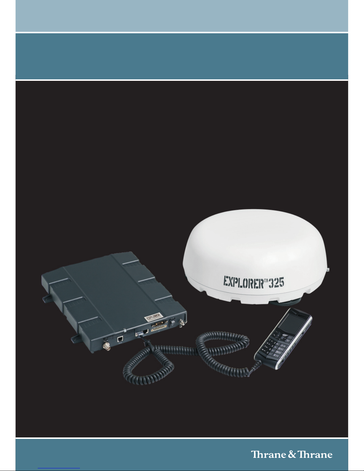
EXPLORER® 325

98-131306-A ii
EXPLORER
®
325
Document number: 98-131306-A
Release date: June 17, 2010
Disclaimer
Any responsibility or liability for loss or damage in connection with the use of this product and the
accompanying documentation is disclaimed by Thrane & Thrane. The information in this manual is provided
for information purposes only, is subject to change without notice and may contain errors or inaccuracies.
Manuals issued by Thrane & Thrane are periodically revised and updated. Anyone relying on this information
should acquire the most current version e.g. from http://www.thrane.com or from the distributor. Thrane &
Thrane is not responsible for the content or accuracy of any translations or reproductions, in whole or in part,
of this manual from any other source.
Copyright © 2010 Thrane & Thrane A/S. All rights reserved.
Trademark acknowledgements
• Thrane & Thrane is a registered trademark of Thrane & Thrane A/S in the European Union and the United
States.
• EXPLORER is a registered trademark of Thrane & Thrane A/S in the European Union and the United States.
• Windows and Outlook are registered trademarks of Microsoft Corporation in the United States and other
countries.
• Inmarsat is a registered trademark of International Maritime Satellite Organisation (IMSO) and is licensed
by IMSO to Inmarsat Limited and Inmarsat Ventures plc.
• Inmarsat’s product names are trademarks or registered trademarks of Inmarsat.
• Other product and company names mentioned in this manual may be trademarks or trade names of their
respective owners.
Company web site
www.thrane.com
98-131306-A iii
Safety summary 1
The following general safety precautions must be observed during all phases of operation, service and
repair of this equipment. Failure to comply with these precautions or with specific warnings elsewhere
in this manual violates safety standards of design, manufacture and intended use of the equipment.
Thrane & Thrane A/S assumes no liability for the customer's failure to comply with these requirements.
Observe marked areas
Under extreme heat conditions do not touch areas of the terminal or
antenna that are marked with this symbol, as it may result in injury.
Microwave radiation hazards
During transmission the antenna in this system radiates Microwave
Power.This radiation may be hazardous to humans close to the antenna.
When the system is powered, make sure that nobody gets closer than the
recommended minimum safety distance.
The minimum safety distance is 0.6 m to the side and above the antenna
when the EXPLORER 325 is powered. The safety distance of 0.6 m does not apply directly below the
antenna, as the radiation forms a hemisphere above the antenna.
Service
User access to the interior of the system units is prohibited. Only a technician authorized by Thrane &
Thrane A/S may perform service - failure to comply with this rule will void the warranty.
Do not service or adjust alone
Do not attempt internal service or adjustments unless another person, capable of rendering first aid
resuscitation, is present.
Power supply
The voltage range is 10.5 - 32 V DC; 11.5 A - 4 A. Be aware of high start-up peak current: 20 A@24 V,
5ms.
Do not operate in an explosive atmosphere
Do not operate the equipment in the presence of flammable gases or fumes. Operation of any
electrical equipment in such an environment constitutes a definite safety hazard.
Keep away from live circuits
Operating personnel must not remove equipment covers. Component replacement and internal
adjustment must be made by qualified maintenance personnel. Do not replace components with the
power cable connected. Under certain conditions, dangerous voltages may exist even with the power
cable removed. To avoid injuries, always disconnect power and discharge circuits before touching
them.
Install and use the antenna with care
Thrane & Thrane assumes no liability for any damage caused by the antenna falling off the vehicle or
stressing the mounting base. It is the responsibility of the customer to ensure a safe and correct
installation of the antenna. The instructions in the Installation manual are only guidelines.

98-131306-A iv
Note the following safety guidelines for mounting the antenna with magnetic mounts:
Under normal driving circumstances the magnetic force of the magnetic mount kit for the antenna
should be sufficient to hold the antenna. However, the magnets may not be able to hold the antenna
in place, if:
• the vehicle is involved in an accident,
• the magnets are not mounted properly,
• the roof is not plain or made of a material that will not stick properly to the magnets,
• the speed of the vehicle is too high and/or
•the road is very bumpy.
We recommend mounting the antenna directly on the roof instead of using the magnetic mount kit.
Make sure that all mounting bolts and nuts are secured properly, and that the material of the
mounting surface is strong enough to hold the antenna during the intended use.
Failure to comply with the rules above will void the warranty!
CAUTION! Do not place your fingers underneath the antenna when placing the
antenna on the vehicle!
The magnetic force is very powerful and your fingers may be hurt if they are caught
between the antenna and the mounting surface.

98-131306-A v
About the manual 2
Intended readers
This is an installation manual for the EXPLORER 325 system, intended for installers of the
system and service personnel. Personnel installing or servicing the system must be properly
trained and authorized by Thrane & Thrane. It is important that you observe all safety
requirements listed in the beginning of this manual, and install the system according to the
guidelines in this manual.
Manual overview
Note that this manual does not cover general use of the system nor does it cover how to use
the IP handset that comes with the system. For this information, refer to the user manual
for this system and the user manual for the IP handset, both listed in the next section.
This manual has the following chapters:
• System units contains a short description of each main unit in the system.
• Installing the system describes where to place the system units, how to mount them,
distance to other equipment etc.
• Connecting power explains how to connect the terminal to power and gives
recommendations for cables.
• Hardware interfaces describes each interface on the terminal and shows pin-out for the
connectors.
• Starting up the system explains how to insert the SIM card, power up the system and
enter the PIN. It also gives a short overview of how to use the system.
• Troublesh ooti ng describes the function of the Reset button and the light indicator on
the terminal. It also describes event messages that may appear in the web interface.

98-131306-A vi
Related documents
The below list shows the documents related to this manual and to the system.
Typ og ra ph y
In this manual, typography is used as indicated below:
Bold is used for the following purposes:
• To emphasize words.
Example: “Do not touch the antenna”.
• To indicate what the user should select in the user interface.
Example: “Select SETTINGS > LAN”.
Italic is used to emphasize the paragraph title in cross-references.
Example: “For further information, see Connecting Cables on page...”.
Title and description
Document
number
EXPLORER 325
User Manual
Explains how to set up and use the
EXPLORER 325 system.
98-131305
EXPLORER 325 Quick Guide
A short guide to the most important
functions of the EXPLORER 325 system.
98-131307
Thrane IP Handset, User Manual
Explains the features and functions of the
Thrane IP Handset. The IP handset works
as a standard IP handset, but also serves
as a user interface for the EXPLORER 325
system.
98-126059

98-131306-A vii
Table of contents
Chapter 1 System units
Introduction ..........................................................................................................1
EXPLORER 325 terminal .......................................................................................1
EXPLORER 325 antenna .......................................................................................1
Thrane IP Handset & Cradle ............................................................................... 2
Chapter 2 Installing the system
Unpacking ............................................................................................................ 3
Placing the antenna ............................................................................................ 4
Installing the antenna ........................................................................................5
Placing the terminal ...........................................................................................10
Installing the EXPLORER 325 terminal .............................................................. 11
Chapter 3 Connecting power
Power source ......................................................................................................13
Power cable selection ........................................................................................13
Connecting power ..............................................................................................18
Chapter 4 Hardware interfaces
The connector panel ......................................................................................... 20
Antenna interface on terminal ..........................................................................21
DC power input .................................................................................................. 22
Analog Phone interface .................................................................................... 23
LAN interface ..................................................................................................... 24
Discrete I/O interface ........................................................................................ 26
Chapter 5 Starting up the system
Using the SIM card ............................................................................................ 29
Powering the system ..........................................................................................31
Entering the SIM PIN for the terminal ............................................................. 32
Operating the system ........................................................................................ 34

Table of contents
98-131306-A viii
Chapter 6 Troubleshooting
Reset button ...................................................................................................... 35
Status signaling ................................................................................................. 37
Logging of events .............................................................................................. 38
Appendix A Part numbers
System units ...................................................................................................... 39
Spare parts ........................................................................................................ 39
Appendix B Technical specifications
Overview ............................................................................................................ 40
EXPLORER 325 antenna .....................................................................................41
EXPLORER 325 terminal .................................................................................... 44
Glossary ............................................................................................................................. 48
Index ..............................................................................................................................51
98-131306-A Introduction 1
Chapter 1
System units 1
Introduction
The basic system consists of three units: The terminal, the antenna and the IP handset with cradle.
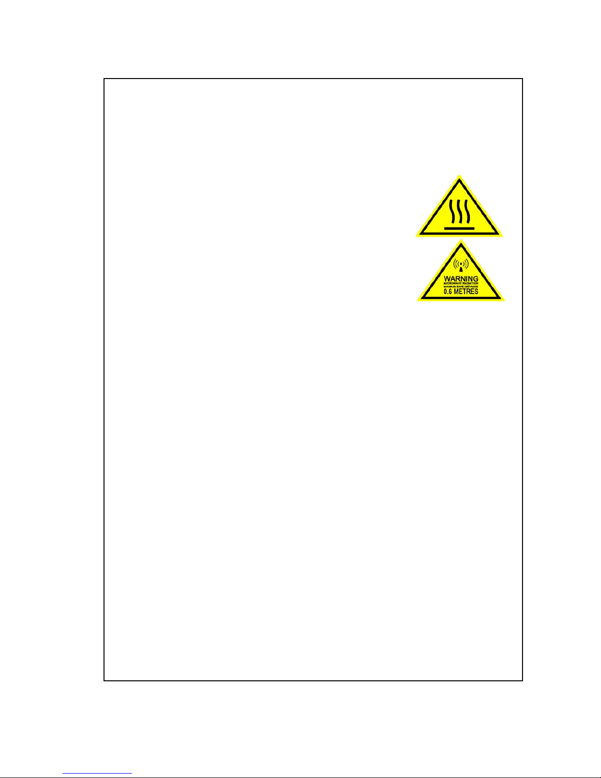
EXPLORER 325 terminal
The terminal is the central unit in the system. It contains all user interfaces and handles all
communication between the BGAN antenna and the local communication units (phones,
computers etc.).
The terminal supplies 23.0 - 30.0 V DC to the antenna through a single coaxial cable.
The DC input for the terminal is designed for both 24 V DC and 12 V DC power supply.
EXPLORER 325 antenna
The EXPLORER 325 antenna is a mechanical tracking antenna, consisting of a 2-axis stabilized
antenna with RF-unit, antenna control unit and GPS antenna. The antenna is dedicated to the
Inmarsat BGAN (Broadband Global Area Network) system and is designed for roof mounting on a
vehicle. All communication between the antenna and terminal passes through a single coaxial
cable.
Chapter 1: System units
98-131306-A Thrane IP Handset & Cradle 2
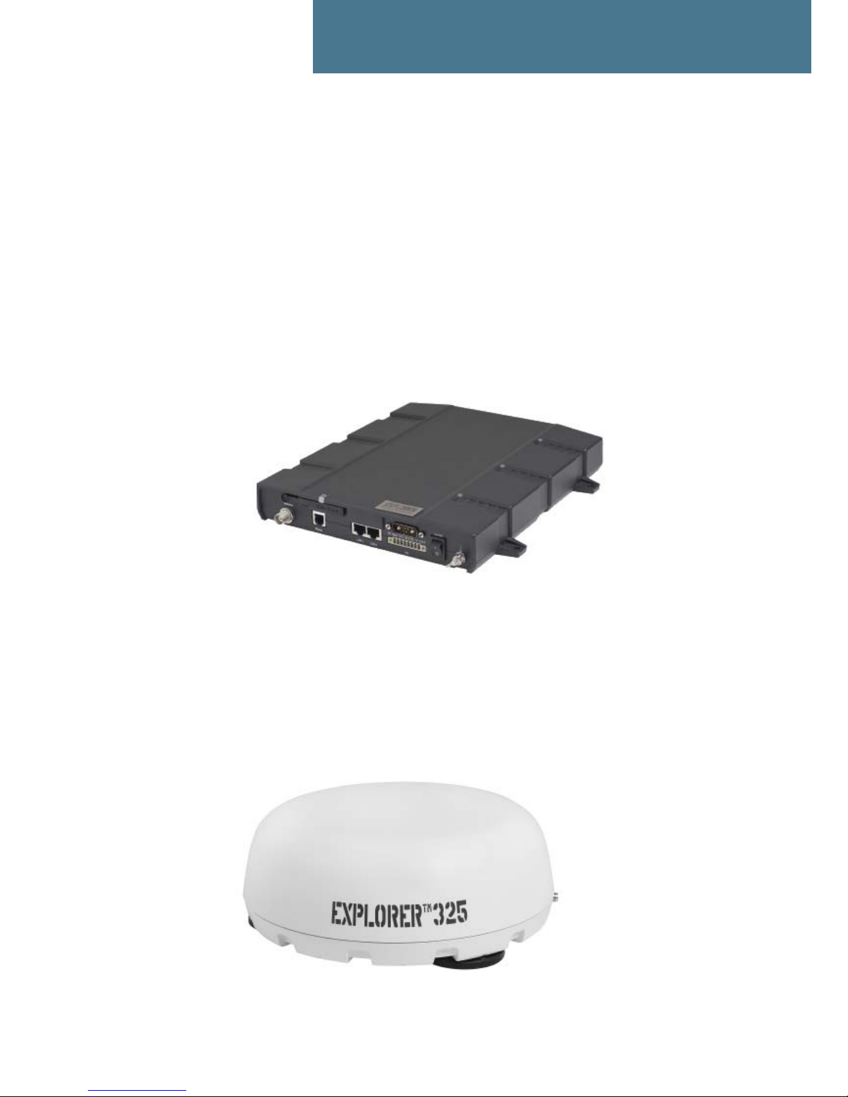
Thrane IP Handset & Cradle
Thrane IP Handset
Besides the normal functions of an IP handset, the Thrane IP handset also provides a user
interface for the EXPLORER 325 system. The IP handset connects to the LAN interface of the
terminal, and is power supplied with Power over Ethernet (PoE) through the LAN interface.
For further information on the IP handset, refer to the user manual for the Thrane IP Handset.
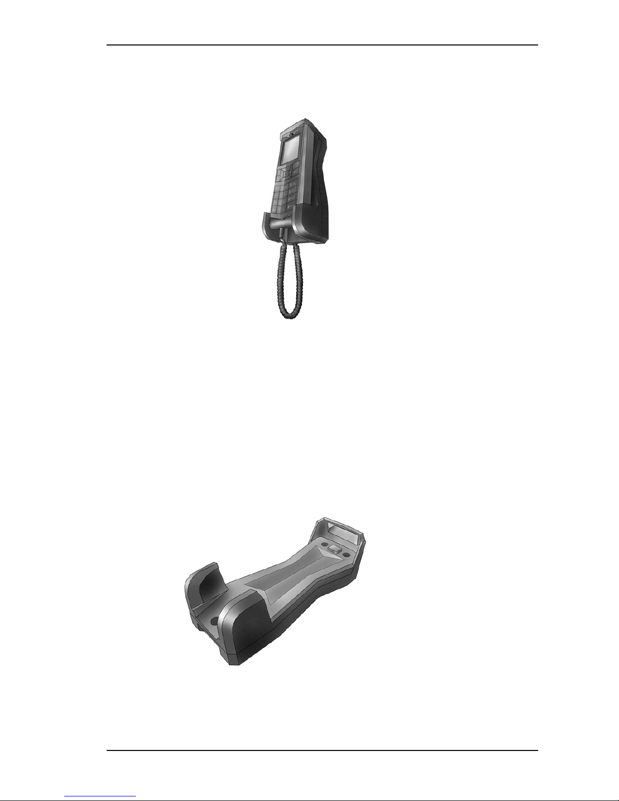
Thrane IP Cradle
The IP cradle serves as a holder for the IP handset. It is power supplied from the terminal using
Power over Ethernet (PoE). The cradle connects to the handset with a coil cord and to the terminal
with a standard LAN cable.

98-131306-A Unpacking 3
Chapter 2
Installing the system 2
Unpacking
Unpack your EXPLORER 325 system and check that the following items are present:
• TT-3733A EXPLORER 325 terminal
• TT-3058A EXPLORER 325 antenna
• TT-3670A Thrane IP Handset & Cradle, wired
•Power cable
•Antenna cable
•LAN cable
• Getting Started kit including:
•Quick Guide
•EXPLORER325 CD
including electronic versions of User manual, Installation manual and Quick Guide.
Inspect all units and parts for possible transport damage.
Note
For information on how to install the IP handset and cradle, refer to the user manual for
the handset.

Chapter 2: Installing the system
98-131306-A Placing the antenna 4
Placing the antenna
Obstructions
Obstructions can cause signal degradation.
The amount of degradation depends on the size of the obstruction and the distance from the
antenna. As a rule of thumb any obstruction that covers an angle of less than 3° at the antenna
has limited effect. The table below gives a guideline for obstruction sizes that will cause limited
degradation.
Radiation hazard
The EXPLORER 325 antenna radiates 15.1 dBW EIRP. This translates to a minimum safety distance
of 0.6 m from the antenna while it is transmitting, based on a radiation level of 10 mW/cm
2
. Note
that the safety distance applies to a hemisphere above the antenna. The antenna does not radiate
power directly below the antenna.
Interference
Do not place the antenna close to interfering signal sources or receivers. We recommend that no
other antennas are located within three meters of the antenna. If other equipment is installed
near the EXPLORER 325 we recommend testing the total system by operating all equipment
simultaneously and verifying that there is no interference.
Distance of Obstruction
Size of
Obstruction
3m 16cm
5m 26 cm
10 m 52 cm
20 m 104 cm
Chapter 2: Installing the system
98-131306-A Installing the antenna 5
Installing the antenna
Antenna cables
Guidelines
A coaxial cable for connection between the antenna and terminal is delivered with the system. If
you need a different cable, make sure that the cable meets the requirements. Preferably choose
one of the cable types in Recommended antenna cables below.
The maximum allowed RF-loss in the antenna cable is 20 dB at 1660 MHz. This is to ensure the
performance of the system.
Recommended antenna cables
The table below shows recommended cable types and maximum cable lengths for EXPLORER 325.
Check in the data sheet from the cable supplier that both the RF- attenuation and the DCresistance are kept within the maximum specified values:
• Antenna cable RF-attenuation at 1660 MHz: max. 20 dB incl. connector.
• Antenna cable modem-attenuation at 54 MHz: max. 4 dB.
Antenna cable modem-attenuation at 36 MHz: max. 3 dB.
• Antenna cable loop DC-resistance max: 0.6 .
Also ensure that the specified minimum bending radius is respected. If this is not the case, the loss
in the cable will increase. Check the instructions from the cable supplier. The bending radius for
the coax cable delivered with the system is min. 110 mm.
CAUTION! It is the responsibility of the customer to
ensure a safe installation! See guidelines in the Safety
summary on page iii.
Cable Type Absolute maximum length
RG-223_U-01 14 m
RG-214_U-01 50 m
S-10162-B-11 92 m

Chapter 2: Installing the system
98-131306-A Installing the antenna 6
Important mounting notes
Line of sight
Place the antenna with free line of sight in all directions to ensure proper reception of the satellite
signal. Do not place the antenna close to large objects that may block the signal.
After installing and starting up the EXPLORER 325, we recommend checking the signal strength
while driving the vehicle in a 360° circle to ensure a clear line of sight in all directions.
Condensation
In some cases there will be condensation inside the antenna. Ventilation holes in the bottom of
the EXPLORER 325 antenna are designed to lead any water away from the antenna.
Make sure these ventilation hole are not blocked.
See Mounting the antenna fixed on the vehicle roof on page 8.
Mounting the antenna
The antenna can now be installed on the roof of the vehicle. You may choose between these
methods:
• Attach the antenna using the magnets underneath the antenna. The magnetic force will keep
the antenna fixed to the vehicle roof. Note that this method requires a vehicle roof made of
magnetizable material.
• Mount the antenna directly on the roof of the vehicle. This method requires that you drill holes
in the roof of the car. Remember to leave min. 10 mm space between the antenna and the roof.
Refer to the Safety summary on page iii.
Important
Make sure there is always a distance of min. 10 mm
between any part of the antenna bottom and the
mounting surface. If the magnets are not used, use 10
mm spacers (or higher if necessary) at each bolt.

Chapter 2: Installing the system
98-131306-A Installing the antenna 7
Magnetic mount
Overview
The antenna comes mounted with 3 individual high intensity magnets with rubber coating. You
can place the EXPLORER 325 antenna directly on the roof of the vehicle using these magnets.
Installing antenna with the magnetic mount kit
To use the magnetic mounts, do as follows:
1. Place the antenna with magnets on the roof of the car. Remember that the magnets only work
on a roof made of magnetizable material!
2. Connect the antenna cable between the terminal and the antenna.
Refer to Antenna cables on page 5.
Detaching the antenna
Grab the antenna near one of the magnets and lift it. When one magnet is loose, the other two are
easier to “break off”.
Note
Make sure the roof of the vehicle is made of a magnetizable material. Wipe the surface
clean before placing the antenna on the roof, in order to make a better connection
between the magnets and the roof and to avoid scratches in the surface.
CAUTION! Do not place your fingers underneath the antenna when placing the
antenna on the vehicle!
The magnetic force is very powerful and your fingers may be hurt if they are
caught between the antenna and the mounting surface.
Chapter 2: Installing the system
98-131306-A Installing the antenna 8
Mounting the antenna fixed on the vehicle roof
The antenna may be fixed on the roof of your car, using three M5 bolts and mounting plates. This
solution requires that you drill three holes in the roof of the car and remove the magnets from the
antenna.
To mount the antenna, do as follows:
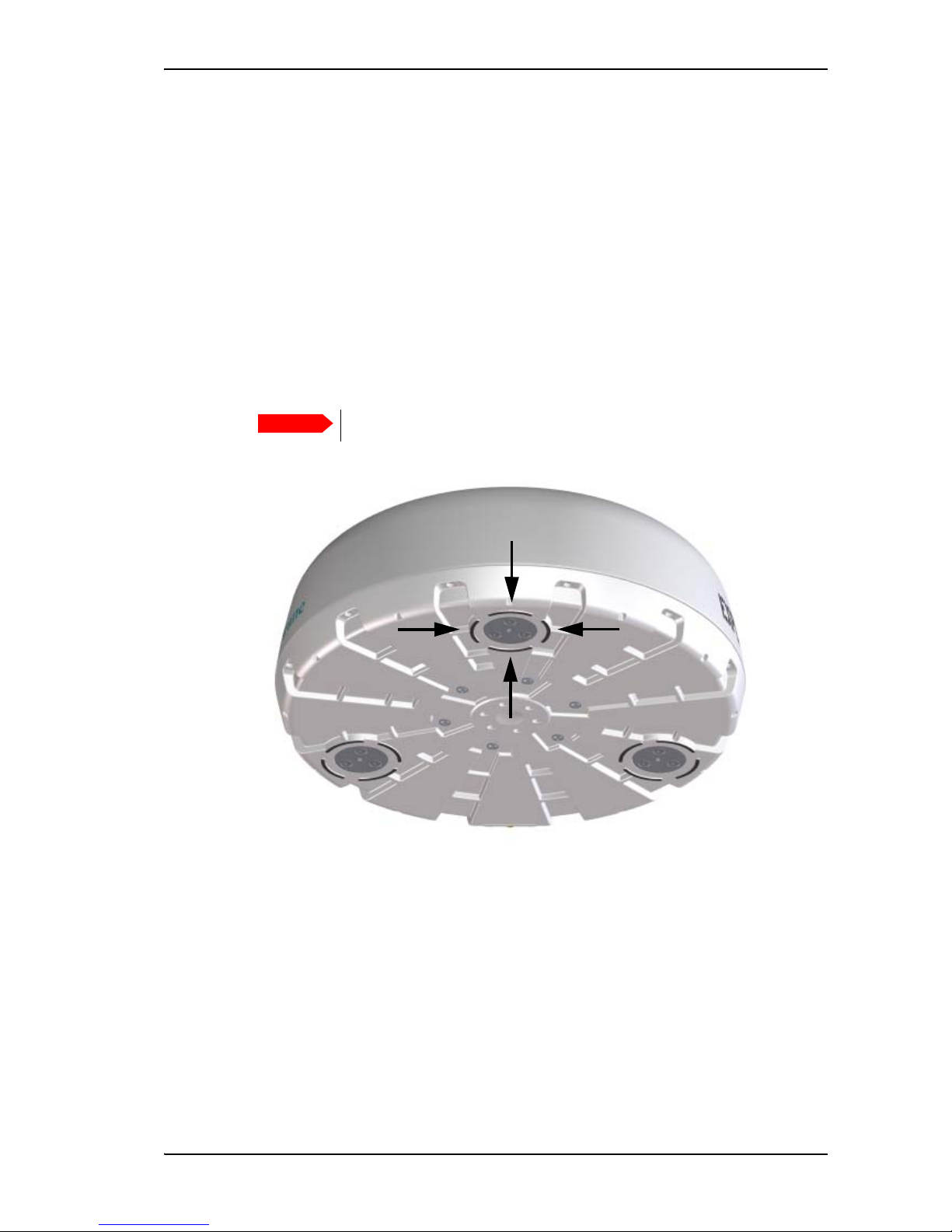
1. Unscrew the 3 magnets from underneath the antenna and remove them.
2. Use mounting plates that, as a minimum, cover the 4 raised areas around each of the 3
mounting bushings. See the drawing below,
Example: You can use 3 mounting plates with a shape and size similar to the magnets
provided with the antenna, i.e. approximately ø90 mm x 10 mm.
Important
Do not mount the antenna without mounting plates!
Chapter 2: Installing the system
98-131306-A Installing the antenna 9
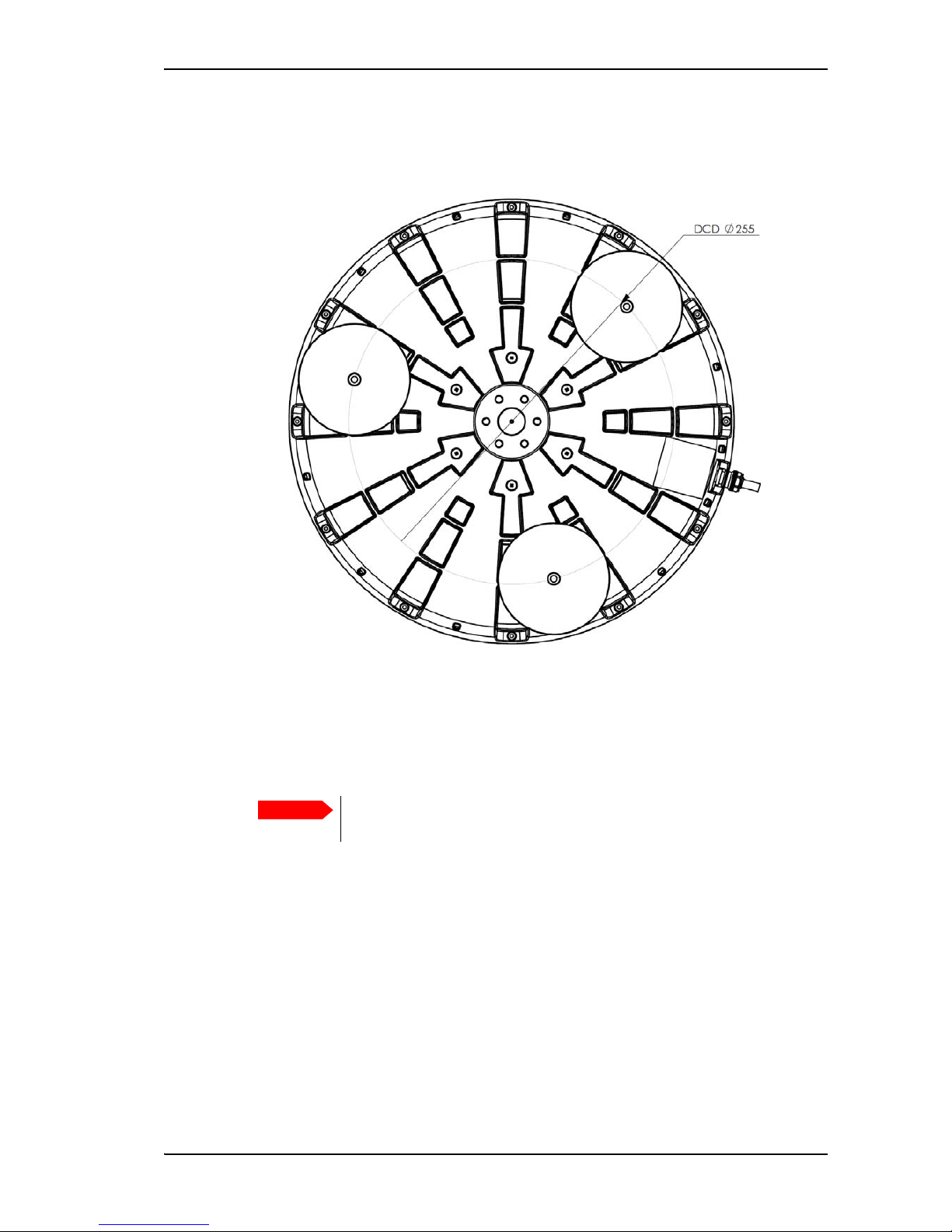
3. Based on the dimensions of the mounting plates, calculate and mark up the position of the
holes to be drilled in the roof of the car. The drawing below shows the Drill Circle Diameter for
the bushings in the antenna. The bushings are 120° apart.
4. Drill the 3 holes in the roof according to the previous step.
5. Mount the antenna with the mounting plates using 3 M5 screws and washers. If the mounting
plates are less than 10 mm thick, use spacers to obtain a minimum distance of 10 mm between
the roof and the antenna bottom. This is to ensure that the ventilation holes in the bottom of
the antenna are not blocked.
Important
The screws must never penetrate more than 10 mm into the bushings in the
antenna!

Chapter 2: Installing the system
98-131306-A Placing the terminal 10
Placing the terminal
Where to place the terminal
General
The terminal is designed for installation inside a vehicle. It is not suited for outdoor installation.
Temperature conditions
The terminal must be placed in a ventilated area with free space around all sides of the unit,
except the bottom side.
Ambient temperature range is –25°C to +55°C.
If the terminal is installed in a location where the ambient temperature may exceed 45°C, we
recommend placing the terminal where unintentional contact is avoided. If the maximum ambient
temperature does not exceed 45°C, the terminal can be placed in a public area.
 Loading...