

Page 1

TT-3060A
Capsat
Mobile Telephone
Users Manual
Page 2

.
Page 3
TELEFAX
TELEFAXTELEFAX
TELEFAX
Warranty Registration
Warranty RegistrationWarranty Registration
Warranty Registration
Congratulations with your new satellite telephone.
In order to registrate in our warranty database please
send this form to Thrane & Thrane, Fax: +45 39 55 88 88.
As an additional benefit we will keep you updated on
enhancements and other news from Thrane & Thrane.
Name: _________________________________________________________
Company:______________________________________________________
Company Fax Number___________________________________________
Company Address ______________________________________________
Company Telephone Number ____________________________________
Estimated number of
POSITION
POSITIONPOSITION
POSITION (
please tick off
)BUSINESS
BUSINESSBUSINESS
BUSINESS Capsat-M users
General Management Governmental 1
Line Management Aid & Rescue 1 - 4
Project Manager Telecom 5 - 10
Site Manager Manufacturing 11 - 20
Engineer, journalist, or Transport 20 - 100
photographer Media > 100
Others: Security
Mining & Drilling
Construction
Tourism
Finance
Trade
Agriculture
Other:
Page 4

.
Page 5

Thrane & Thrane
Thrane & Thrane Thrane & Thrane
Thrane & Thrane
AAAA
/S
/S/S
/S
TT-3060A
Capsat
Mobile Telephone
Users Manual
Copyright Thrane & Thrane A/S
ALL RIGHTS RESERVED
Page 6

Information in this document is subject to change without notice and
does not represent a commitment on the part of Thrane & Thrane A/S.
© 1996 Thrane & Thrane A/S. All rights reserved.
Printed in Denmark.
Document Number TT-98-107770B Release Date: 12Oct01
Page 7

SAFETY SUMMARY
SAFETY SUMMARYSAFETY SUMMARY
SAFETY SUMMARY
The following general safety precautions must be observed during all
phases of operation, service and repair of this equipment. Failure to
comply with these precautions or with specific warnings elsewhere in
this manual violates safety standards of design, manufacture and
intended use of the equipment
Thrane & Thrane A/S assumes no liability for the customers failure to
comply with these requirements.
MICROWAVE RADIATION HAZARDS
MICROWAVE RADIATION HAZARDSMICROWAVE RADIATION HAZARDS
MICROWAVE RADIATION HAZARDS
During transmission this telephone radiates Microwave Power from
the front side of the antenna unit (the side pointed towards the
satellite). This radiation may be hazardous if exposed directly to
human close to the antenna. During transmission, make sure that
nobody gets closer than the recommended minimum safety distance.
GROUND THE EQUIPMENT
GROUND THE EQUIPMENTGROUND THE EQUIPMENT
GROUND THE EQUIPMENT
If the equipment is equipped with a three-terminal AC power
connector, please observe the following:
The power cable must either be plugged into an approved three
contact electrical outlet, or used with a three-contact to two-contact
adapter with the grounding wire firmly connected to an electrical
ground (safety ground) at the power outlet.
Page 8

KEEP AWAY FROM LIVE CIRCUITS
KEEP AWAY FROM LIVE CIRCUITSKEEP AWAY FROM LIVE CIRCUITS
KEEP AWAY FROM LIVE CIRCUITS
Operating personnel must not remove equipment covers. Component
replacement and internal adjustment must be made by qualified
maintenance personnel. Do not replace components with the power
cable or battery connected. Under certain conditions, dangerous
voltages may exist even with the power cable removed. To avoid
injuries, always disconnect power and discharge circuits before
touching them.
DO NOT SERVICE OR ADJUST ALONE
DO NOT SERVICE OR ADJUST ALONEDO NOT SERVICE OR ADJUST ALONE
DO NOT SERVICE OR ADJUST ALONE
Do not attempt internal service or adjustments unless another person,
capable of rendering first aid resuscitation, is present.
RECHARGEABLE BATTERY
RECHARGEABLE BATTERYRECHARGEABLE BATTERY
RECHARGEABLE BATTERY
The product that you have purchased contains a rechargeable
battery. The battery is recyclable. At the end of it's useful life, under
various state and local laws it may be illegal to dispose a Ni-Cd
battery into municipal waste stream. Check with your local solid
waste officials for details in your area for recycling option or proper
disposal. Do not try to disassemble the battery.
Ni-Cd
Ni-CdNi-Cd
Ni-Cd
Page 9

Introduction
12Oct01
Page i
TABLE OF CONTENTS
TABLE OF CONTENTSTABLE OF CONTENTS
TABLE OF CONTENTS
1 Introduction .................................................................................. 1-1
Satellite Telephone Communication............................................. 1-1
2 Installation .................................................................................... 2-1
System Components ..................................................................... 2-1
Precautions ................................................................................... 2-2
Battery Pack .................................................................................. 2-2
Antenna ........................................................................................ 2-3
Antenna Pointing .......................................................................... 2-7
Terminal Operations ..................................................................... 2-8
3 Getting Started ............................................................................. 3-1
Handset......................................................................................... 3-1
Display Symbols and Indicators ................................................ 3-2
Keypad Functions ...................................................................... 3-4
Locate Ocean Region .................................................................... 3-5
SIM Card insertion ........................................................................ 3-6
Power ON ..................................................................................... 3-7
Terminal Set-up ............................................................................ 3-9
4 Call Types..................................................................................... 4-1
Numbers ....................................................................................... 4-1
Number Formats ........................................................................ 4-2
Examples Of Telephone Dial Formats ....................................... 4-4
Voice Calls.................................................................................... 4-7
Receiving Handset Calls ............................................................... 4-7
Receiving Auxiliary Phone Calls................................................ 4-9
Making Handset Calls ................................................................ 4-10
Making Auxiliary Telephone Calls ............................................ 4-13
Key Entries After Connection .................................................... 4-16
Microphone ............................................................................... 4-16
Call Transfer .............................................................................. 4-16
Fax Calls ....................................................................................... 4-17
Page 10

Introduction
Page ii
12Oct01
Receiving Fax Calls.................................................................... 4-17
Making Fax Calls........................................................................ 4-18
Making Fax Calls From The Handset ......................................... 4-21
Data Calls...................................................................................... 4-21
Receiving Data Calls ..................................................................4-22
Making Data Calls ......................................................................4-24
Making Data Calls From The Handset........................................ 4-27
Data Modes ................................................................................ 4-27
AT Command Set ....................................................................... 4-28
5 Menu System................................................................................. 5-1
Help Desk ..................................................................................... 5-1
Phone Book ...................................................................................5-2
Accessing The Phone Book ........................................................5-3
The Phone Book Display ............................................................ 5-4
Direct Short Code Selection .......................................................5-4
Add Entry................................................................................... 5-5
Edit Entry ................................................................................... 5-6
Delete Entry ...............................................................................5-7
Print Phone Book........................................................................ 5-7
Prepaid ......................................................................................... 5-7
Area .............................................................................................. 5-8
Default LES ....................................................................................5-9
Mailbox .........................................................................................5-10
Call log.......................................................................................... 5-10
Calls Total ..................................................................................... 5-12
PIN Codes ..................................................................................... 5-12
PIN1 setting ................................................................................ 5-16
PIN1............................................................................................ 5-16
PIN2............................................................................................ 5-16
CONFIG PIN ............................................................................... 5-16
SIM Lock PIN .............................................................................. 5-16
Config ........................................................................................... 5-16
Aux/ Fax Configuration.............................................................. 5-17
Voice carrier ..............................................................................5-17
Page 11

Introduction
12Oct01
Page iii
Sleep Mode (not Capsat® Maritime Telephone) ....................... 5-17
Data Setup.................................................................................. 5-17
Contrast ..................................................................................... 5-18
Ring Setup.................................................................................. 5-18
Key Beep.................................................................................... 5-19
Antenna Beep ............................................................................ 5-19
Set Time ..................................................................................... 5-19
LES ............................................................................................. 5-20
Route IDs.................................................................................... 5-23
Allowed Dial .............................................................................. 5-25
PhBook Dial................................................................................ 5-26
Auto Prefix ................................................................................. 5-26
Bar Service................................................................................. 5-27
Help Desk .................................................................................. 5-27
SIM Lock .................................................................................... 5-28
Prepaid ...................................................................................... 5-28
STU............................................................................................. 5-29
Log to Prn................................................................................... 5-29
Noise Immun.............................................................................. 5-29
Billing Tone................................................................................ 5-29
Antenna ..................................................................................... 5-30
Accessories................................................................................ 5-31
Status ............................................................................................ 5-33
C/No .......................................................................................... 5-33
Battery ....................................................................................... 5-33
Transceiver................................................................................ 5-33
SIM Card.................................................................................... 5-34
RF Block ..................................................................................... 5-34
Bulletin....................................................................................... 5-35
Antenna ..................................................................................... 5-36
Print ........................................................................................... 5-39
Alarm Log ..................................................................................... 5-40
Delete Alarms ............................................................................ 5-41
Print Alarm Log .......................................................................... 5-41
Spot Beam ..................................................................................... 5-41
Page 12

Introduction
Page iv
12Oct01
Tel. Numbers ................................................................................ 5-42
6 Technical Reference ..................................................................... 6-1
Equipment List .............................................................................. 6-1
Technical Specifications................................................................ 6-2
Power Requirements .....................................................................6-4
TT-3007A, Mini M – Patch Antenna................................................ 6-5
Antenna Cables............................................................................. 6-7
Handset .........................................................................................6-8
Battery Pack Handling ................................................................... 6-9
Charge Indicator........................................................................... 6-9
Fast Charge................................................................................ 6-10
Standard Charge........................................................................ 6-11
Interface........................................................................................ 6-11
Solar Panel Interface/Light Weight Power Supply Connector,X1 . 6-12
DC Input / Fast Charge Power Supply Connector, X2 .................. 6-14
Antenna Cable plug, X3 ................................................................ 6-15
DTE Interface, X4 .......................................................................... 6-15
Phone/Fax Connectors, X5............................................................ 6-17
Handset Connector, X6 and X7 ..................................................... 6-18
TT-3007A Patch Antenna connector, X8 ........................................6-19
Appendix A - List of Abbreviations ...................................................A-1
Appendix B - Antenna Azimuth & Elevation ......................................B-1
Appendix C - List of Land Earth Stations .......................................... C-1
Appendix D - 2-Digit Service Codes ................................................ D-1
Appendix E - Tone Signals................................................................E-1
Appendix F - List of Cause Codes ..................................................... F-1
Appendix G - List of System Errors .................................................. G-1
Appendix H - Trouble Shooting ........................................................H-1
Appendix I - Extended Error Codes .................................................. I-1
Appendix J - Search Algorithms .........................................................J-1
Appendix K - AT Command Set......................................................... K-1
Appendix L Spot Beam Coverage ..................................................... L-1
Page 13

Introduction
12Oct01
Page v
Page 14

Page 15

Introduction
12Oct01 Page 1-1
1
1 1
1 IIII
NTRODUCTION
NTRODUCTIONNTRODUCTION
NTRODUCTION
This manual describes the Capsat® Telephone.
The Capsat
®
Telephone is a mobile Inmarsat-phone mini-M terminal
which provides access to international telephone, facsimile and data
networks.
SSSS
ATELLITE
ATELLITE ATELLITE
ATELLITE
TTTT
ELEPHONE
ELEPHONE ELEPHONE
ELEPHONE
CCCC
OMMUNICATION
OMMUNICATIONOMMUNICATION
OMMUNICATION
Operating the Capsat® Telephone is much the same as making direct
international telephone calls from an ordinary telephone.
The difference is that the Capsat
®
Telephone communicates directly
with a satellite and therefore does not rely on a local telephone
operator to route the call to the desired destination. Instead, the calls
to/from the satellite are routed by designated Land Earth Stations
(LESs) which also communicates with the same satellite as the
telephone terminal.
The necessary requirements to operate a satellite telephone is that
a) the terminal is registered by a service provider (i.e. payment
arrangements).
b) the location where the telephone is located is covered by a
satellite, and
c) there is a free line of sight from the antenna of the terminals to the
satellite.
The satellite system used by the Capsat
®
Telephone is operated by
the international organisation, Inmarsat. The system consists of four
satellites which combined guarantee world-wide coverage (see
appendix B for coverage maps).
When working with the Inmarsat-phone mini-M system, the following
abbreviations are often used:
Page 16

Introduction
Page 1-2
12Oct01
MES Mobile Earth Station.
This is the name that Inmarsat uses for terminals.
E.g. the Capsat
®
Telephone is a MES. Mobile refers to the fact
that the terminals are re-locatable.
Earth Station is a satellite communication term.
LES Land Earth Station.
The LES is located at the "other" end of the MES's satellite link.
The LES connects to the local telephone networks and manages
calls to and from the MES.
NCS Network Co-ordination Station.
The NCS is responsible for assigning communication channels
to the MESs. In case of NCS failure the MESs will switch to
"Stand-Alone" mode. In Stand-Alone mode designated LESs in
each ocean region will act as NCS.
Page 17
Installation
12Oct01 Page 2-1
2
2 2
2 IIII
NSTALLATION
NSTALLATIONNSTALLATION
NSTALLATION
Please read trough Technical Reference section before installing the
equipment.
SSSS
YSTEM
YSTEM YSTEM
YSTEM
CCCC
OMPONENTS
OMPONENTSOMPONENTS
OMPONENTS
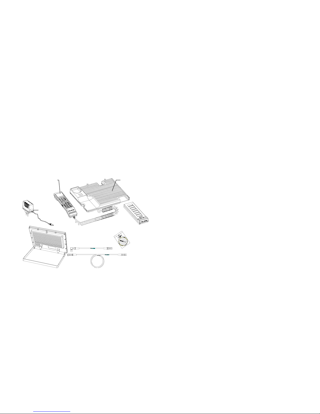
Figure
Figure Figure
Figure 2
2 2
2 ----1111: TT-3060A Capsat Mobile Telephone
: TT-3060A Capsat Mobile Telephone: TT-3060A Capsat Mobile Telephone
: TT-3060A Capsat Mobile Telephone
Electronics
Unit
Operator
Handset
Patch Antenna
Light Weight
Power Supply
Antenna Cable
5.0 m SMB
Antenna Cable 0.15 m SMB
Compass
NiCd
Battery Pack
Page 18
Installation
Page 2-2
12Oct01
PPPP
RECAUTIONS
RECAUTIONSRECAUTIONS
RECAUTIONS
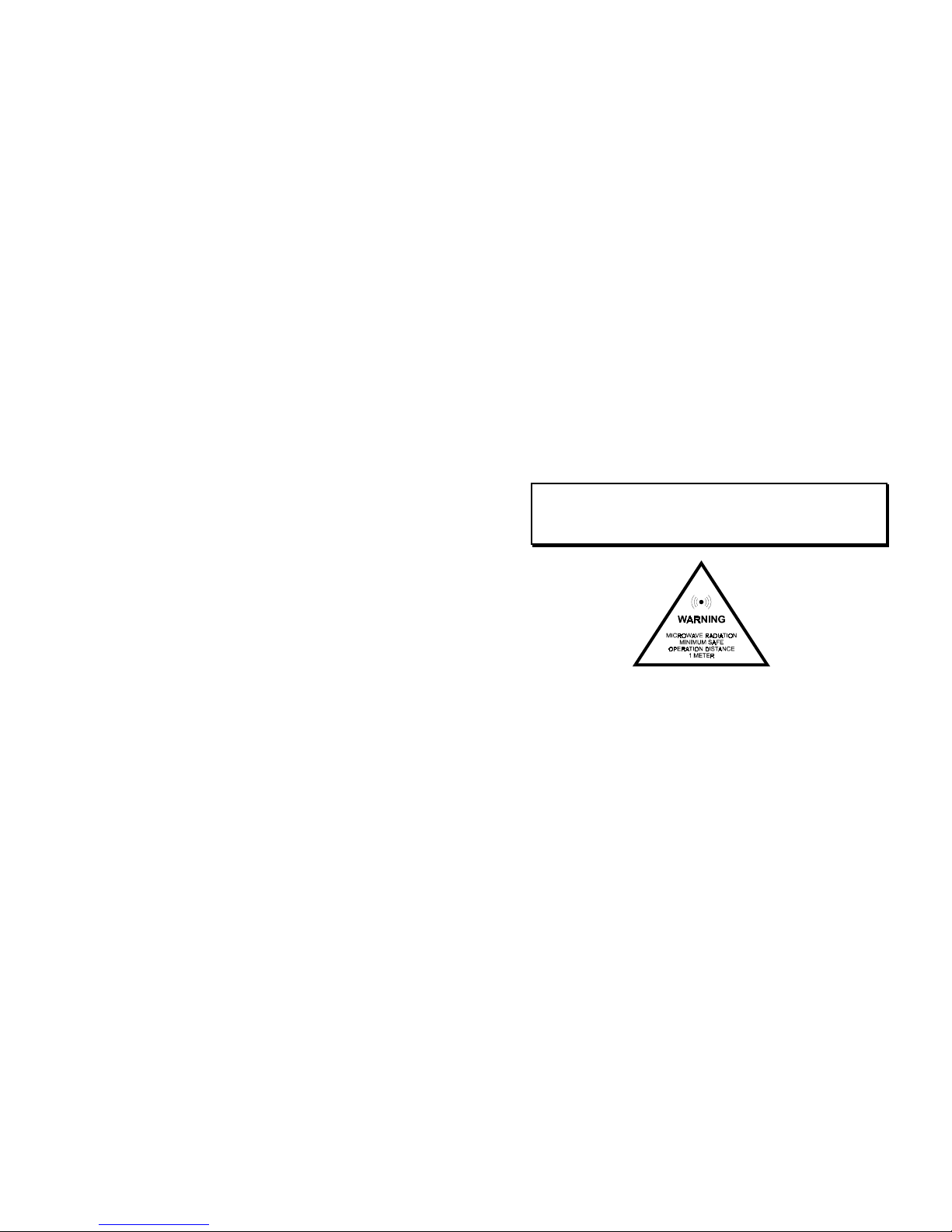
The antenna unit radiates RF signals during a telephone call with the
strongest radiated signal on the focal line of the antenna and drops off
fairly quickly. Therefore allow a safety passage distance of 1 meter
around the antenna. Below is shown a safety guidance labels which
must be observed carefully.
Warning !
The TT-3007A Antenna radiates microwave signals.
Keep 1 meter of safety distance from the antenna
BBBB
ATTERY
ATTERY ATTERY
ATTERY
PPPP
ACK
ACKACK
ACK
Proper handling of the Battery Pack is important to obtain maximum
talk and listen time. It is also a requirement for the warranty to cover
the Battery Pack.
To ensure proper handling follow the steps below:
I. Discharge the battery completely on regular basis, e.g. after 5 - 10
partial discharges. This will prevent the so called "memory effect"
in the battery cells which reduces their capacity.
I. Avoid exposing the Battery Pack to direct sunlight, as high
temperatures will reduce battery lifetime.
Page 19

Installation
12Oct01 Page 2-3
I. In cold environment (0° Celsius and below) preheat the Battery
Pack if possible to e.g. body temperature before making calls. A
cold battery has less useful capacity than a warm battery (hence
longer talk time are obtained by preheating the battery).
I. Disconnect the small AC adapter when the Battery Pack is
completely recharged. Continuos over-charging of the Battery
Pack causes its temperature to rise. This will on the long term
damage the Battery Pack.
The procedure to discharge the Battery Pack is :
a) Disable the Telephone's sleep mode (see chapter 5).
a) Disconnect the Power Supply.
a) Leave the telephone on until the green POWER LED turns off.
When completely discharged then reconnect the Power Supply,
recharge the Battery Pack completely and re-enable the sleep mode.
If the Battery Pack continues to discharge rapidly, it may help to
repeat the discharge/recharge cycle an additional 2-5 times.
Refer to the Technical Reference in chapter 6 for more information on
battery handling and alternative power supplies.
The battery indicator in the handset display shows an estimate of the
remaining battery capacity.
The remaining capacity is estimated by monitoring battery over a
period of time. In sleep mode the battery is not monitored, therefore
the capacity estimate immediately after a sleep mode deactivation is
incorrect. The estimate will approach the correct value in
approximately one minute.
AAAA
NTENNA
NTENNANTENNA
NTENNA
The TT-3060A's antenna (TT-3007A) resides naturally on top of the
Electronics Unit. It is kept in place by two vertical guide pins located
on the rear top of the electronics unit and is connected with a short
(0.15 m) antenna cable to the Electronics Unit.
Page 20

Installation
Page 2-4
12Oct01
The antenna can be used directly on the Electronics Unit by rotating
the entire unit until its rear end points toward the satellite (the azimuth
angle) and then by opening the antenna (like a lid hinged on to the
rear of the unit), until it forms an angle with vertical equal to the
satellite elevation angle.
A detailed explanation for setting up the antenna will follow later.
With the long antenna cable the antenna can be placed up to 5 m from
the Electronics Unit. Before removing the antenna from the
Electronics Unit, the short antenna cable must be disconnected from
the antenna. It may otherwise be damaged.
On the bottom / back side of the antenna is a frame which serves as a
foot for the antenna when placed separately from the Electronics Unit.
The frame is hinged to the same tube which fits over the guide pins in
the Electronics Unit. When the antenna is mounted on the Electronics
Unit, the frame is fixed to the antenna by a small pin opposite the
tube. To open the frame it must first be released from the antenna by
lifting
it over the pin (see the following figures). Before the antenna
and frame can be tilted to the correct angle, the frame must be
opened until a 'click' is heard. How much the frame needs to be
opened before the 'click' depends on the angle of the antenna when
removed from the Electronics Unit: If the antenna is positioned
vertically when removed the 'click' should occur almost immediately,
if the antenna is positioned horizontally the frame needs to be opened
approximately 90° before the 'click'.
Page 21
Installation
12Oct01 Page 2-5
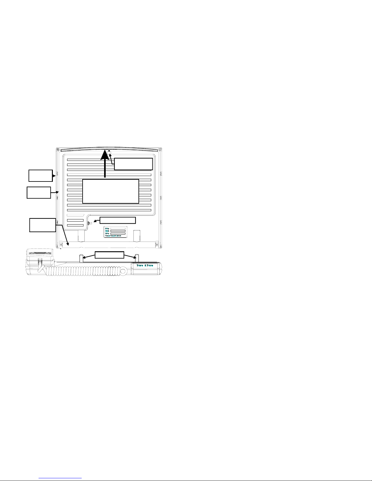
Figure
Figure Figure
Figure 2
2 2
2 ----2222 Antenna Frame
Antenna Frame Antenna Frame
Antenna Frame
NOTE: WHEN RETURNING THE ANTENNA TO THE ELECTRONICS
UNIT, MAKE SURE THAT TUBE COVERS THE GUIDE PINS
COMPLETELY AND IS FLUSH WITH THE ELECTRONICS UNIT
BEFORE ANY ATTEMPTS ARE MADE TO ROTATE THE ANTENNA
TO HORIZONTAL POSITION.
ANTENNA JACK
ANTENNA
STAND
To release the antenna
stand from the frame pull
slightly up in the stand and
open.
GUIDE PINS
ANTENNA
FRAME
FRICTION
TUBE
ANTENNA FOOT
LOCK PIN
Page 22
Installation
Page 2-6
12Oct01
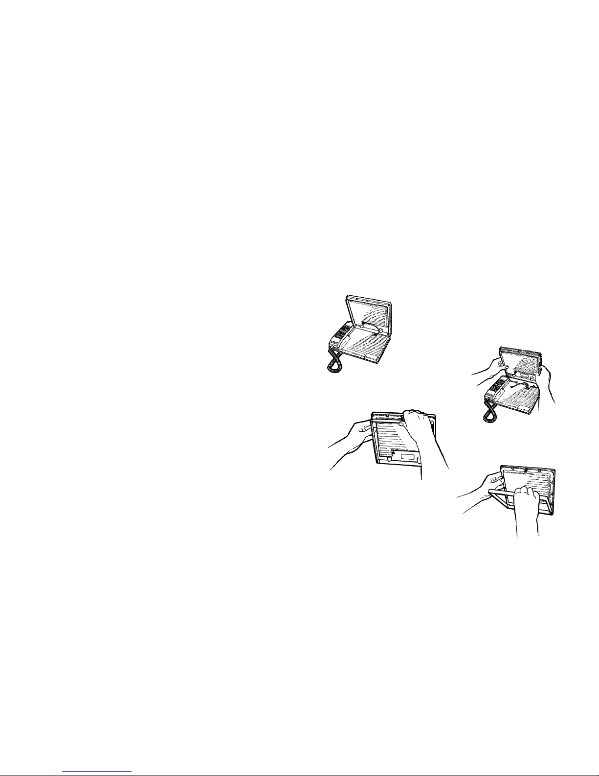
The figures below illustrates how to remove the antenna from the
Electronics Unit.
STEP 4
STEP 4 STEP 4
STEP 4 Open antenna stand
until it locks to the frame.
STEP 1
STEP 1 STEP 1
STEP 1 Open antenna to vertical.
STEP 2
STEP 2 STEP 2
STEP 2 Disconnect
antenna cable before
removing the antenna
with both
bothboth
both hands.
STEP 3
STEP 3 STEP 3
STEP 3 Release the antenna stand
from the frame.
Page 23
Installation
12Oct01 Page 2-7
AAAA
NTENNA
NTENNA NTENNA
NTENNA
PPPP
OINTING
OINTINGOINTING
OINTING
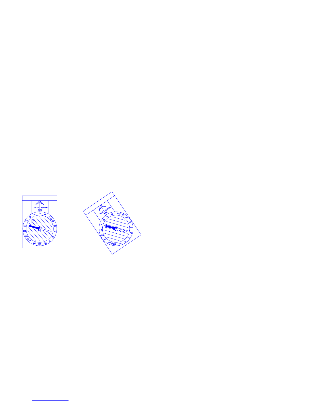
Once the satellite has been located, the antenna should be directed
towards the satellite.
Follow the directions below:
• Use the enclosed 5m antenna cable TT 37-104481 if you want to
place the antenna separate from the Electronics Unit.
• Find the selected Area on the antenna maps and read the
approximate azimuth (0-360 degrees) to the satellite from your
present geographical position.
• Turn the dial on the compass for the correct azimuth angle e.g. 40
degrees points to the arrow marked 'Read bearing here'.
• Turn the compass without changing the dial until the red needle
(North) coincides with the big arrow inside the compass dial
(Figure 2 -1).
Figure
Figure Figure
Figure 2
2 2
2 ----1111 Compass
Compass Compass
Compass
• The arrow marked 'Read bearing here' on the compass is now
pointing towards the satellite in horizontal direction. Adjust the
antenna into this direction.
Page 24

Installation
Page 2-8
12Oct01
NOTE: AVOID USING THE COMPASS IN THE VICINITY OF
MAGNETIC MATERIAL (E.G. IRON, FERRO-CONCRETE ETC.) IT
CAN OFFSET THE BEARING SIGNIFICANTLY !
• The antenna must be pointed at the satellite with a free line-of-
free line-of-free line-of-
free line-of-
sight
sightsight
sight.
• Now read the approximate elevation (0-90 degrees) to the
satellite from your present geographical position using the
antenna maps.
• The antenna can be tilted into any vertical angle. There are no
readings on the antenna for the elevation angle. When setting the
elevation angle start with the antenna in vertical position and then
tilt it the number of degrees equal to the elevation angle.
(Hint: The compass can aid finding the correct antenna angle
a) set the dial to the elevation angle
b) position the compass vertical with the "READ BEARING" arrow
pointing up
c) look at the parallel lines within the dial, they have the correct
angle.
)
TTTT
ERMINAL
ERMINAL ERMINAL
ERMINAL
OOOO
PERATIONS
PERATIONSPERATIONS
PERATIONS
The TT-3060A Capsat Mobile Telephone has three modes of
operations relating to its power consumption.
In the POWER OFF mode the terminal is turned off and no power is
used. In this mode the terminal will not detect any calls or messages
sent to it.
In the POWER ON mode the terminal is capable of making outgoing
calls and receiving incoming calls.
The power consumption is moderate to high depending on the state of
the terminal. Data and FAX calls consume more power than voice
calls. If no FAX or auxiliary telephone are connected to the mini-M
phone, the power consumption can be reduced further by disabling
the AUX/FAX interface completely
1
1
See the description of the configuration option in chapter 5.
Page 25

Installation
12Oct01 Page 2-9
When the terminal is left unused for 60 seconds it will automatically
go into SLEEP-mode, unless the feature is disabled
1
.
SLEEP mode - In this mode the terminal will power up in short
intervals to check for incoming calls. The green POWER LED lights up
in short bursts. The transition to SLEEP-mode is made from POWER
ON either when commanded by the user with the LOCK command
(), or when the handset has been idle for 60 seconds duration.
The terminal returns to POWER ON mode if
a) an incoming call is detected, or
b) a key is pressed on the keypad.
In this mode outgoing calls cannot be initiated from the AUX PHONE
/FAX interface. The terminal must first be brought into POWER ON by
activating the handset.
Page 26

Page 27
Getting Started
12Oct01 Page 3-1
3
3 3
3 GGGG
ETTING
ETTING ETTING
ETTING
SSSS
TARTED
TARTEDTARTED
TARTED
This section describes how to set up the Capsat® Telephone to make
and receive telephone calls for the first time. All operation of the
telephone is performed at the handset which briefly will be
introduced below.
HHHH
ANDSET
ANDSETANDSET
ANDSET
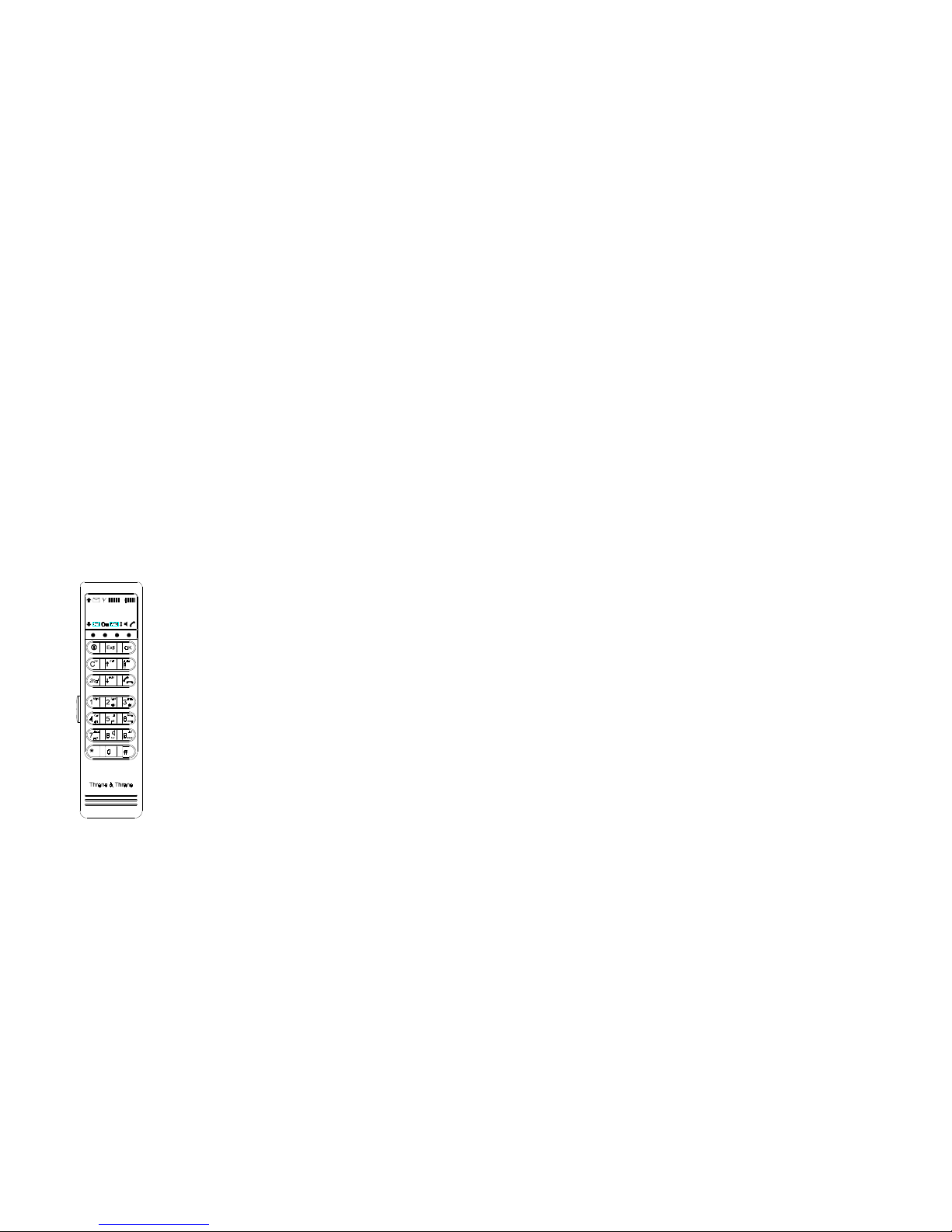
The handset is equipped for full operation and access of the Capsat
®
Telephone terminal. It contains indicators, LCD display and keypad
together with microphone, ear-piece and adjustable volume. The
handset is illustrated below.
Figure
Figure Figure
Figure 3
3 3
3 ----1111: Handset Display Symbols
: Handset Display Symbols: Handset Display Symbols
: Handset Display Symbols
DISPLAY SYMBOLS
More entries above
More entries below
Signal strength
Battery capacity
(Only portable)
2nd-button pressed
Security enabled
Alpha mode on
Toggle field
Speaker on
Hook off
New message
V
O
L
U
M
E
Page 28
Getting Started
Page 3-2
12Oct01
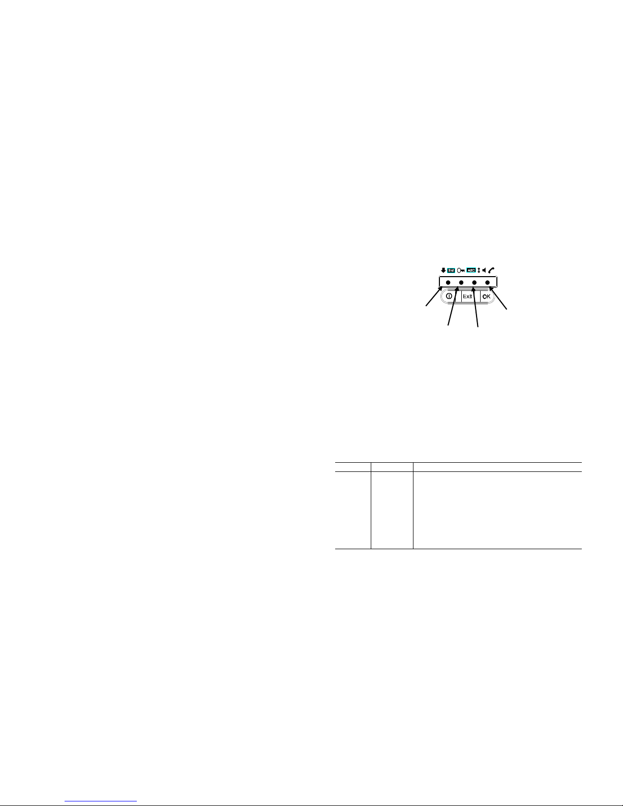
Figure
Figure Figure
Figure 3
3 3
3 ----2222: Handset Indicators
: Handset Indicators: Handset Indicators
: Handset Indicators
Display Symbols and Indicators
The state of the terminal is signalled in the LCD display on the
handset. The display has 2 lines of 12 characters for textual messages
and 11 special symbols.
The description for the individual LED's are found in Table 1. Table 2
contains the description for the LCD display symbols.
Table
Table Table
Table 1111 User Indicator LEDs
User Indicator LEDs User Indicator LEDs
User Indicator LEDs
NAME COLOUR DESCRIPTION
POWER GREEN Lights steadily when the terminal is on.
Flashes when in sleep-mode.
ALARM RED Lights red when an alarm is present
RING YELLOW Flashes yellow when ringing. Lights steadily
during call.
SYNC GREEN Lights green when in synchronisation with
NCS.
SYNC
(green)
RING
(yellow)
POWER
(green)
ALARM
(red)
INDICATORS
Page 29

Getting Started
12Oct01 Page 3-3
Table
Table Table
Table 2222 User Display Symbols
User Display Symbols User Display Symbols
User Display Symbols
SYMBOL NAME DESCRIPTION
More
Entries
Above
Indicates that additional entries are
available above and can be accessed by
pressing the key.
More
Entries
Below
Indicates that additional entries are
available below and can be accessed by
pressing the key.
Signal
Strength
Indicates the strength of the received
signal. When tuned to a satellite this
indicator is updated approximately once
each second. When searching for a satellite
to tune to it may take up to 11 seconds
before it is updated.
Battery
Capacity
Only Capsat® Mobile Telephones.
Shows the current capacity of the battery.
For a fully charged battery all four bars
should be lit.
2nd-Button
Pressed
Indicates that the button was pressed
and the 2
nd
function of the next key pressed
will be interpreted. E.g. when is lit and
the key is pressed then the
Mute
function is executed.
Security
Enabled
When lit, the terminal can only be accessed
by entering a valid PIN code.
Alpha
Mode On
Indicates that the keypad is in alpha mode
and expects alphanumeric words to be
entered.
Toggle
Field
Used to indicate that the current input field
is changed by pressing the or keys.
SpeakerOnThe speaker in the Electronic Unit is on.
Hook Off The handset is off the hook.
New
Messages
A recorded message for the terminal/SIM is
waiting at a LES to be heard.
Page 30

Getting Started
Page 3-4
12Oct01
Keypad Functions
The keys on the keypad have multiple functions. Which of the
functions of the key that are activated when pressed depends on the
mode of the keypad. The current mode of the keypad is signalled by
the and indicators in the display (see Table 3).
Table
Table Table
Table 3333 Keypad Mode
Keypad Mode Keypad Mode
Keypad Mode
INDICATOR (none)
+
MODE NORMAL ALPHA 2ND 2ND
In Table 4 all keypad functions are listed.
In ALPHA MODE the different symbols for the numeric keys (-)
are selected by pressing the same key repeatedly until the desired
symbol is displayed. The cursor will automatically advance to the
next position 2 seconds after the key is pressed. If an error is
detected in the entered string of symbols the clear key, , must be
pressed until the symbol can be re-entered.
Page 31

Getting Started
12Oct01 Page 3-5
Table
Table Table
Table 4444 Keypad Functions
Keypad Functions Keypad Functions
Keypad Functions
KEY NORMAL MODE ALPHA MODE 2ND MODE
Power on/off. Must be held
for 3 seconds to switch off.
Exit Menu / Cancel
selection
Accept selection
Delete / Back space Delete / Back space Insert entry
Move one selection up Edit entry
Enable Alpha Mode Disable Alpha Mode Delete entry
Enable 2nd Mode Enable 2nd Mode Disable 2nd Mode
Move one selection down Print Topic
1
Toggle Hook
1 - ? ! , . : " ' $ ( ) + / 1 Activate Main Menu
2 A B C 2 Lock / Sleep mode
3 D E F 3 Area Selection
4G H I 4Fax Call
5 J K L 5 R (re-route call)
6M N O 6Mute
7 P Q R S 7 Data Call
8 T U V 8 Toggle SPEAKER
9 W X Y Z 9 Toggle antenna beep
*
0 (Force cursor move) Help Desk
#<space>
LLLL
OCATE
OCATE OCATE
OCATE
OOOO
CEAN
CEAN CEAN
CEAN
RRRR
EGION
EGIONEGION
EGION
The Inmarsat mini-M system is based on four satellites to provide
global coverage.
Each satellite has a coverage area which is defined as the area on the
surface of the earth where it can "see" the Inmarsat-phone mini-M
terminals in a free line of sight.
1
The topic printed is determined by current menu
Page 32

Getting Started
Page 3-6
12Oct01
The coverage maps for the satellites are placed in appendix L, and
the antenna maps for azimuth & elevation are placed in appendix B of
this manual.
The maps show the individual coverage areas, corresponding to the
four satellites for the following areas / ocean regions:
• Atlantic Ocean Region West (AORW)
• Atlantic Ocean Region East (AORE)
• Pacific Ocean Region (POR)
• Indian Ocean Region (IOR)
SIM C
SIM CSIM C
SIM C
ARD INSERTION
ARD INSERTIONARD INSERTION
ARD INSERTION
The Capsat® Telephone may require an INMARSAT SIM Card inserted
before it will be operational. The SIM Card contains ID's and
additional information (phone books).
The SIM Card can be inserted or removed at any time without
damaging the transceiver by removing the SIM Card cover located at
the side of the telephone, however as the operation changes the
identity of the Capsat
®
Telephone, calls in progress will be terminated
and the transceiver will be initialised.
When inserted the following data will be retrieved from and stored on
the SIM card : phone book, call log, tel. numbers, LES lists, PIN1 and
PIN2.
The SIM Card is inserted with the golden contact area pointing down
and heading towards the Electronic Units SIM Card Slot, refer to
Figure 3 -3.
Page 33

Getting Started
12Oct01 Page 3-7
Capsat® Telephone
without the
protective
cover
SIM
CARD
Insert the SIM Card with the
Gold contact area pointing
downwards and into the SIM
Card slot
Figure
Figure Figure
Figure 3
3 3
3 ----3333: SIM Card insertion
: SIM Card insertion: SIM Card insertion
: SIM Card insertion
PPPP
OWER
OWER OWER
OWER
ON
ONON
ON
Once the equipment is installed then power up the terminal by
pressing the key on the handset.
The normal sequence for the handset on power-up is:
• The whole LCD display is filled with solid blocks, all indicators
and symbols in LCD display are turned On for about 2 seconds.
• Writes 'Initialising' for some seconds.
• Writes 'PIN code'. This step is omitted if PIN 1 is disabled. Enter
your PIN code.
Only Capsat® Mobile Telephones (see appendix J for further
information).
• Writes 'Search for satellite'.
• Move the antenna/Capsat® Telephone until the handset
writes '<Area> Accept ?', where <Area> is the name of the
Area/Ocean Region wanted.
• Press to accept the found and wanted Area/Ocean
Region.
Page 34

Getting Started
Page 3-8
12Oct01
Only Capsat® Compact Carphone, Capsat® Disc and
Maritime Telephones (see appendix J for further information).
• The Capsat® Telephone will find the satellite
automatically. While searching the handset writes
messages as 'Full skyscan started', 'Initial skyscan started',
'Re. skyscan started' and 'Step track. started'. Please see
appendix J for further information.
• Writes one of the following texts.
1) If no Bulletin Board has been received the handset will display
the currently selected Area/Ocean region and the text 'Wait
for NCS' as an indication that the Capsat® Telephone is still
waiting for the Bulletin Board to arrive.
IOR:
Wait for NCS
(note: If no bulletin board arrive after a while, proceed with the
"Terminal Set-Up" section below and try another Area/Ocean
Region)
2) If the Bulletin board has been received the handset will
display the currently selected Area/Ocean Region and the
name/LES Access Code of the default selected LES.
IOR:PTT TELE
_
The Bulletin Board contains information needed for operation in
the Inmarsat-phone mini-M network system. Without the Bulletin
Board no operations like telephone calls etc. can be done.
The Capsat® Telephone will automatically update the display
from 1) to 2) when the Bulletin Board is received.
Page 35

Getting Started
12Oct01 Page 3-9
If the antenna has been connected after power-up or if it is not
connected at all you will get an alarm message. Check that the
antenna is connected correctly. The alarm message can be removed
pressing the $-key.
The Capsat® Telephone is now in Idle Mode
Idle ModeIdle Mode
Idle Mode.
NOTE (Only Capsat® Compact Carphone and Capsat® Disc
Telephones): The vehicle must NOT be turning during the first 5
seconds after switching on the system. This period is used to calibrate
the initial gyro offset. The total change in vehicle direction during this
period should be less than 5 degrees.
TTTT
ERMINAL
ERMINAL ERMINAL
ERMINAL
SSSS
ET
ETET
ET
----
UP
UPUP
UP
Before the Capsat® Telephone can go into operation an Area/Ocean
Region must be selected.
• Select the Area that you want to operate in. The current selected
Area is marked with an '*' in the Area list.
If you want to use the already selected Area press the $-key and
return to Idle Mode without making any changes.
Enter the Area list
Choose an Area
Accept selection
If the new Area is successfully selected the Capsat® Telephone
will write an acknowledge message. Otherwise an error message
will be displayed.
• The Capsat® Telephone will perform an initial sky-scan search
and will obtain synchronisation with the Network Co-ordinating
Station (NCS) within a short time. Wait for the green sync indicator
on the handset.
Furthermore the Bulletin Board is received. Wait until the handset
display is updated as specified in the previous section.
• First time an Area is selected for operation a random LES is
selected as default. When you are making e.g. an outgoing
Page 36

Getting Started
Page 3-10
12Oct01
satellite call the default LES is used for that call unless another LES
specifically has been chosen for the call.
If you are using the selected Area for the first time select a default
LES. The current default selected LES is marked with an '*' in the
LES list.
If you want to use the already selected LES press the $-key and
return to Idle Mode without making any changes.
Enter the Main Menu *-
Scroll and select Default LES
-
&
Choose a LES
Accept selection &
If the new default LES is successfully selected the Capsat®
Telephone will write an acknowledge message. Otherwise an
error message will be displayed.
The Capsat® Telephone is now ready for operation.
Page 37

Call Types
12Oct01 Page 4-1
4
4 4
4 CCCC
ALL
ALL ALL
ALL
TTTT
YPES
YPESYPES
YPES
The Capsat® Telephone distinguishes between three types of
telephone calls:
• Voice Calls
• Fax Calls
• Data Calls
Each of the three types of calls are routed to a separate connector on
the terminal:
Call Type Destination
Voice HANDSET, or
AUX/FAX
connector
FAX AUX/FAX
connector
Data DCE port
If the PIN1 security key is enabled and the Capsat® Telephone is in
sleep mode it is required to login on the terminal handset, prior to
making calls from an auxiliary telephone, a fax machine or the data
interface. However, it is always possible to receive calls.
NNNN
UMBERS
UMBERSUMBERS
UMBERS
There are four types of numbers which can be dialled from the
Capsat® Telephone:
• Subscriber Numbers
Ordinary telephone numbers of subscribers.
• Short Codes
Two digit codes which refer to entries in the telephone book. The
Page 38

Call Types
Page 4-2
12Oct01
short code numbers must always be preceded by when
entered.
• Service Codes
Also two digit codes (but not preceded by ) which refers to
optional services provided by the Land Earth Stations. See
Appendix D for a list.
• Local Numbers
With an auxiliary telephone connected to the AUX/FAX port it is
possible to make local calls from the handset to the auxiliary
telephone and vice versa.
The local call codes are one digit numbers.
Dialling numbers is simple once connected with a LES:
From the handset just enter the telephone number and press either
, & or to initiate the call.
On the auxiliary telephone use the pound button to initiate the
call.
NOTE: When dialling short codes pressing once the telephone
number will be displayed and a second press is required to initiate
the call.
Number Formats
In the following the general dial formats for telephone numbers is
described.
All mandatory fields are marked <field>. All optional fields are
marked [field]. All the fields must be separated with . Leading
optional fields may be left out completely, but if other optional fields
are left out you still have to enter an to indicate an empty field.
The dial formats are shown for auxiliary telephone calls where the offhook key and & is unavailable. On the handset all trailing
pound-buttons can be substituted by a single or & press, i.e. the
sequence can be substituted by or &.
Page 39

Call Types
12Oct01 Page 4-3
The fields that make up the number are:
• The Terrestrial Network ID
Terrestrial Network ID Terrestrial Network ID
Terrestrial Network ID (TNID) field holds a 3-digit value and
specifies the telephone network to be used.
• 0 Terrestrial Network unspecified (default value)
• 1..255 Terrestrial Network ID 1..255
In most countries only one telephone network exists.
• The LES
LESLES
LES field holds a 3-digit value and specifies the LES Access
Code that shall be used for the actual telephone call. If no LES field
is specified the default LES will be used.
• The Type
TypeType
Type field holds a 1-digit value and specifies the type of call:
• 0 for AUX Phone calls
• 1 for AUX FAX calls
The value of the type field will over
• The Phone number
Phone numberPhone number
Phone number field specifies the subscriber number to be
called including call prefix for automatic calls (00) and country
code (e.g. 45 for Denmark). It holds up to 22 digits.
Subscriber Number Format:
Handset: [Terr. Network IDO] [LesO]<Phone number>Q
Aux.Phone: [Terr. Network IDO] [LesO][TypeO]<Phone
number>Q
OR
<Phone number>Q
Short Code Format :
Handset: O[Terr. Network IDO] [LesO]<Short code>Q
Aux.Phone: O[Terr. Network IDO] [LesO][TypeO]<Short
code>Q
OR
O<Short code>QQ
Service Code Format:
Page 40

Call Types
Page 4-4
12Oct01
<2 Digit Service Code>Q
Local Call Format:
<1 Digit Local Code>Q
Examples Of Telephone Dial Formats
Manual Telephone Calls
Manual Telephone CallsManual Telephone Calls
Manual Telephone Calls
Enter call prefix for automatic calls
Enter country code
Enter telephone number
Start the call
A telephone number can be called entering the telephone number
and accepted using the Q-key. The telephone number may not
exceed 22 digits including call prefix for automatic calls and country
code.
The default LES will be used for the call.
Telephone Call On A Fax Interface
Telephone Call On A Fax InterfaceTelephone Call On A Fax Interface
Telephone Call On A Fax Interface
Enter type as voice
Enter separator
Enter call prefix for automatic calls
Enter country code
Enter telephone number
Start the call
If the 2-wire phone/fax port is used mainly as a fax interface it is
normally set to fax in the configuration menu (Config, Aux/Fax conf.,
Fax). When dialling a number, the terminal will then assume that the
call is a fax call. However, it is possible to overrule this setting from
the 2-wire phone/fax and make a voice call by dialling: 0*<number>.
The call must be accepted using the -key.
Page 41

Call Types
12Oct01 Page 4-5
The telephone number may not exceed 22 digits including call prefix
for automatic calls and country code.
Telephone Call Of Last Number Dialled
Telephone Call Of Last Number DialledTelephone Call Of Last Number Dialled
Telephone Call Of Last Number Dialled
Enter short code for last number dialled
Retrieve a list of the last telephone numbers dialled
Select a number in the list
To accept a number press
Start the call
The short code ‘0’ represents the last telephone number dialled.
Pressing the -key once will display a list of the last up to 20
numbers dialled. It is now possible to scroll through the list and select
a number by pressing the -key. You can accept it with a second
press on the -key or you may change the number.
Local Call
Local CallLocal Call
Local Call
Enter local call code
Start the call
A local call is a call between the Capsat® Telephone and auxiliary
phone. Calls can be initiated from both ends. Different from other
types of calls it is not necessary to be in synchronisation with the NCS
to make a local call. A local call will not be stored in the call log.
Any key between and can be used as local call code..
Telephone Call Of 2-Digit Code
Telephone Call Of 2-Digit CodeTelephone Call Of 2-Digit Code
Telephone Call Of 2-Digit Code
Enter 2-digit code
Start the call
All 2-digit service codes are described in appendix D.
A call to a 2-digit code service is normally made entering the 2-digit
code and accept it using the -key. However some 2-digit code
services require an appended string with telephone number, credit
card number etc.
Page 42

Call Types
Page 4-6
12Oct01
The 2-digit code represents special services such as operator
assistance, commissioning etc. supported by the LESs. The services
supported depend on the LES.
Telephone Call From Telephone Book
Telephone Call From Telephone BookTelephone Call From Telephone Book
Telephone Call From Telephone Book
Enter the Phonebook
Choose a subscriber
Select and display the subscriber telephone number &
Start the call
The telephone book can be entered using the or -key. Inside
the telephone book a particular subscriber may be selected and
displayed using the &-key. You may change the number or simply
accept using the -key.
Telephone Call Using Short Code
Telephone Call Using Short CodeTelephone Call Using Short Code
Telephone Call Using Short Code
Enter short code prefix
Enter short code
Display the corresponding telephone number
Start the call
Refer to section 'Phonebook' in chapter 5 for general information
about short codes.
The short code prefix in front of the short code must be entered. If not
the call will be recognised as a 2-digit code call or a local call.
The first press on the -key will display the telephone number
corresponding to the entered short code. The telephone number may
be changed or accepted with a second press on the -key.
Page 43

Call Types
12Oct01 Page 4-7
VVVV
OICE
OICE OICE
OICE
CCCC
ALLS
ALLSALLS
ALLS
Telephone calls can only be made or received if
• Bulletin Board has been received from NCS
e.g. the display shows 'IOR:PTT TELE'.
• Capsat® Telephone is in synchronisation with NCS,
i.e. the green sync indicator lights steadily
RRRR
ECEIVING
ECEIVING ECEIVING
ECEIVING
HHHH
ANDSET
ANDSET ANDSET
ANDSET
CCCC
ALLS
ALLSALLS
ALLS
In the following an incoming call to the handset is described. The
handset will ring and the yellow RING indicator will flash. The call can
be answered in two ways:
1. Press the ,-key
This will establish the connection and enable the microphone and
ear-piece. If the handset is in the cradle the speaker in the terminal
will also be enabled. The RING indicator lights steadily during the
connection.
2. Lift handset out of the cradle
This will establish the connection and enable the microphone and
ear-piece. The RING indicator lights steadily during the
connection.
During the call you can use the volume control at the side of the
handset to control the speech level. The -key combination
enables/disables the speaker in the terminal. The D-symbol shows
whether the speaker is On/Off. To mute the microphone press .
When muted the Off-hook indicator will flash in the display.
Calls are cleared in two ways.
1. Pressing the ,-key.
2. Place the handset in the cradle when the speaker is Off ( i.e. the D
indicator is off).
Page 44

Call Types
Page 4-8
12Oct01
If you place the handset in the cradle with the speaker On you will
not clear the call. You will have to press the , key.
If the call is cleared by the calling subscriber or cleared in an
abnormal way you will hear a congestion tone in the earpiece/speaker as an indication of a call clearing. If you do not press
the ,-key within 10 seconds the handset will go on-hook
automatically.
Refer to appendix E for more information about the tone signals.
An error message will be displayed if the call is cleared in an
abnormal way.
Land mobile and maritime terminals have some additional
capabilities which are described in the Accessories paragraph in
Chapter 5.
Page 45

Call Types
12Oct01 Page 4-9
Receiving Auxiliary Phone Calls
In the following an incoming call to the auxiliary telephone connected
to the AUX/FAX connector, x5, is described.
NOTE:
The text in brackets specifies actions taken by the user. The
messages in boxes specify the status of the auxiliary phone call
displayed in the handset. These messages are only displayed if the
handset is out of the menu system.
Phone is ringing
ringing
Phone
(Answer the call)
Phone connected with
subscriber
connected
Phone-Phone
Clear the call
(Place phone on-hook)
If the call is cleared by the calling subscriber or cleared in an
abnormal way you will hear a congestion tone as an indication of a
call clearing. The phone must be placed on-hook before a new call
can be established.
Refer to appendix E for more information about the tone signals.
An error message will be displayed if the call is cleared in an
abnormal way.
Note: Due to the power saving scheme, devices connected to the X5
Phone/Fax Connector cannot wake the Capsat® Telephone up from
sleep mode.
Page 46

Call Types
Page 4-10
12Oct01
Making Handset Calls
NOTE:
The messages in boxes specify the status of the handset call
displayed in the handset. These messages are only displayed if the
handset is out of the menu system.
Apart from local calls and 2-digit "short code" calls (see below),
handset calls can be separated into two kinds of calls:
1. Calls To Ordinary Telephone Numbers
2. Calls To Other Inmarsat-Phone Mini-M Terminals
Procedure To Call Ordinary Telephone Numbers
Procedure To Call Ordinary Telephone NumbersProcedure To Call Ordinary Telephone Numbers
Procedure To Call Ordinary Telephone Numbers
Enter call prefix for
automatic call
Enter country code
Enter telephone number
Start the call
Handset is calling
calling
Handset
Handset connected with
LES
connected
Handset-LES
Handset connected with
subscriber
connected
Handset-Ph.
Enable/Disable speaker
Clear the call
0:02:24
Call logged
Page 47

Call Types
12Oct01 Page 4-11
Procedure To Call Other Inmarsat-Phone Mini-M Terminals
Procedure To Call Other Inmarsat-Phone Mini-M TerminalsProcedure To Call Other Inmarsat-Phone Mini-M Terminals
Procedure To Call Other Inmarsat-Phone Mini-M Terminals
Enter call prefix for
automatic call
Enter country code
Enter IMN
Start the call
Handset is calling
calling
Handset
Handset connected with
LES
connected
Handset-LES
Handset connected with
subscriber
connected
Handset-Ph.
Enable/Disable speaker
Clear the call
0:02:24
Call logged
The international codes (“country code”) to the Areas/Ocean
Regions are listed in Table 5. Using the 870 country code (Single
Network Access Code, SNAC) automatically routes the call to the
Mini-M terminal via the proper Area/Ocean Region.
Table
Table Table
Table 5555 Ocean Region Access Codes
Ocean Region Access Codes Ocean Region Access Codes
Ocean Region Access Codes
Ocean Region International Access Code
SNAC 870
Atlantic Ocean East Region 871
Pacific Ocean Region 872
Indian Ocean Region 873
Atlantic Ocean West Region 874
Page 48

Call Types
Page 4-12
12Oct01
If the call is accepted by the Capsat® Telephone it will start the call
procedure and display the message 'Handset calling'.
When the Capsat® Telephone has established the call to the LES the
message 'Handset-LES connected' will be displayed. The LES now
calls the subscriber.
When the subscriber answers the call the message 'Handset-Ph.
connected' will be displayed. The RING indicator lights steadily
during the connection.
The billing of the call starts when the subscriber answers the call and
there is an end-to-end connection between the Capsat® Telephone
and the subscriber. Note that only outgoing satellite calls are billed.
Outgoing calls are cleared identically to incoming calls.
If the call is billed, payment information is stored in the call log and
the call duration is displayed for some seconds in the display.
Page 49

Call Types
12Oct01 Page 4-13
Making Auxiliary Telephone Calls
NOTE:
The texts in brackets specify actions taken by the user. The
messages in boxes specify the status of the auxiliary phone call
displayed in the handset. These messages are only displayed if the
handset is out of the menu system.
As for handset calls, auxiliary calls are also grouped into regular calls
and calls to other Inmarsat-phone mini-M terminals.
Calling Ordinary Telephone Number From The Auxiliary Telephone
Calling Ordinary Telephone Number From The Auxiliary TelephoneCalling Ordinary Telephone Number From The Auxiliary Telephone
Calling Ordinary Telephone Number From The Auxiliary Telephone
• Auxiliary phone call to an ordinary telephone number connected
to the national PSTN.
Enter call prefix for
automatic call
Enter country code
Enter telephone number
Start the call
Telephone is calling
calling
Phone
Telephone connected
with LES
Phone-LES
connected
Telephone connected
with subscriber
connected
Phone-Phone
Clear the call
(Place phone on-hook)
0:02:24
Call logged
Page 50

Call Types
Page 4-14
12Oct01
Calling Other Inmarsat-Phone Mini-M From The Auxiliary Telephone
Calling Other Inmarsat-Phone Mini-M From The Auxiliary TelephoneCalling Other Inmarsat-Phone Mini-M From The Auxiliary Telephone
Calling Other Inmarsat-Phone Mini-M From The Auxiliary Telephone
Enter call prefix for
automatic call
Enter country code
Enter IMN
SSSSSSSS
Start the call
Telephone is calling
calling
Phone
Telephone connected
with LES
Phone-LES
connected
Telephone connected
with subscriber
connected
Phone-Phone
Clear the call
(Place phone on-hook)
0:02:24
Call logged
The international codes (“country code”) to the Areas/Ocean
Regions are listed in Table 5. Using the 870 country code (Single
Network Access Code) automatically routes the call to the Mini-M
terminal via the proper Area/Ocean Region.
If the call is accepted by the Capsat® Telephone it will start the call
procedure and display the message 'Phone calling'.
When the Capsat® Telephone has established the call to the LES the
message 'Phone-LES connected' will be displayed. The LES now calls
the subscriber.
When the subscriber answers the call the message 'Phone-Phone
connected' will be displayed.
The billing of the call starts when the subscriber answers the call and
there is an end-to-end connection between the Capsat® Telephone
and the subscriber. Note that only outgoing satellite calls are billed.
Page 51

Call Types
12Oct01 Page 4-15
If the call is cleared by the calling subscriber or cleared in an
abnormal way you will hear a congestion tone in the telephone as an
indication of a call clearing. The phone must be placed on-hook
before a new call can be established.
Refer to appendix E for more information about the tone signals.
The Capsat® Telephone will display an error message if the call is
cleared in an abnormal way.
If the call is billed, payment information is stored in the call log and
the call duration is displayed for some seconds in the display.
Page 52

Call Types
Page 4-16
12Oct01
Key Entries After Connection
During an end-to-end connection (incoming or outgoing satellite call)
between the Capsat® Telephone and the subscriber, additional key
entries might be necessary for direct dialling through PABX systems,
voice response systems etc. The tones generated from pressing the
keys are called DTMF tones.
The handset must be out of the menu system to invoke DTMF tones.
The keys which generate DTMF tones are the number, pound, and the
asterisk keys (-, and ).
For the auxiliary telephone simply press the P-N, O and Q-
keys to invoke the DTMF tone.
Microphone
During an end-to-end connection (incoming or outgoing satellite call)
between the Capsat® Telephone and a subscriber the microphone in
the handset can be muted.
Press *2 on the handset to mute the microphone. Subsequently a
press of any handset key will set the microphone back to normal
again.
The handset will display the messages ‘Microphone Off’ when the
microphone is muted and ‘Microphone On’ when the microphone is
back to normal. The handset has to be out of the menu system to show
these messages.
Call Transfer
During an end-to-end connection (incoming or outgoing satellite call)
between the Capsat® Telephone and the subscriber it is possible to
transfer the call between the handset and the auxiliary telephone
connected to the terminal.
The call transfer is activated by pressing the ‘R’ -key. On the handset
the ‘R’-key is generated with the combination .
Page 53

Call Types
12Oct01 Page 4-17
Below an example is given:
A
UXILIARY TELEPHONE
H
ANDSET
Satellite call established
R
(Local call of handset)
Ringing
,
Talk
Talk
Place phone on-hook
Satellite call established
The unit having the satellite call can take back the satellite call at any
time during the procedure pressing the R-key a second time.
Technically, the R-key makes an On-hook, Off-hook with a
maximum spacing of 150 ms. If the auxiliary phone does not have a
R-key and is of good quality it might be possible to simulate the
key, flashing the hook switch.
If the call is billed each part of the call will be stored separately in the
call log. The example above will give two entries in the call log, one
for auxiliary phone call and one for handset call.
FFFF
AX
AX AX
AX
CCCC
ALLS
ALLSALLS
ALLS
Fax calls can only be made or received if
• The AUX/FAX port is configured to FAX.
• Bulletin Board has been received from NCS
• The Capsat® Telephone is synchronised with the NCS.
Not two fax machines work identically. Therefore this description may
not be complete. Additional information may be obtained from your
fax manual supplied with the fax machine.
Receiving Fax Calls
In the following an incoming fax call to a fax machine connected to the
AUX/FAX connector, x5, is described.
Page 54

Call Types
Page 4-18
12Oct01
A fax call is normally answered and cleared automatically.
NOTE:
The texts in brackets specify automatic actions taken by the fax
machine. The messages in boxes specify the status of the fax call
displayed in the handset. These messages are only displayed if the
handset is out of the menu system.
Fax is ringing
ringing
Fax
(Answer the call)
Fax connected with
subscriber
connected
Fax-Fax
Negotiating
Negotiating
Receiving page x
Receiving
page 1
Page x confirmed
Page 1
confirmed
Receive successful
Receive
successful
Clear the call
(Fax placed on-hook)
An error message is displayed if the call is cleared in an abnormal
way.
Making Fax Calls
If the fax machine has a keypad the dial number can be entered
directly from this keypad.
Page 55

Call Types
12Oct01 Page 4-19
The texts in brackets specify automatic actions taken by the fax
machine. The messages in boxes specify the status of the fax call
displayed in the handset. These messages are only displayed if the
handset is out of the menu system.
Procedure To Call Ordinary FAX Numbers
Procedure To Call Ordinary FAX NumbersProcedure To Call Ordinary FAX Numbers
Procedure To Call Ordinary FAX Numbers
Press Hook-key to get
proceed-to-dial tone
Enter call prefix for
automatic call
Enter country code
Enter fax number
Start the call
Press Start-key to send
fax
Fax is calling
calling
Fax
Fax connected with LES
connected
Fax-LES
Fax connected with
subscriber
connected
Fax-Fax
Negotiating
Negotiating
Sending page x
page 1
Sending
Page x confirmed
Page 1
confirmed
Page 56

Call Types
Page 4-20
12Oct01
Sending successful
successful
Sending
Clear the call
(Fax placed on-hook)
0:02:24
Call logged
Press the Hook-key on the fax keypad to get a proceed-to-dial tone.
Secondly the dial number must be entered and ended with the -
key to start the call.
If the call is accepted by the Capsat® Telephone it will start the call
procedure and display the message 'Fax calling'.
When the Capsat® Telephone has established the call to the LES the
message 'Fax-LES connected' will be displayed. The LES now calls the
subscriber fax.
When the called fax answers the call the message 'Fax-Fax connected'
will be displayed.
Press the Start-key before or when you get connection with the called
fax machine. Some fax machines only allow 5 or 6 ringing sequences
from the Start-key is pressed and until the call must be answered. In
this case you must wait to press the Start-key until the call is being
answered.
If the Start-key is not pressed the message ‘Press Start on fax’ will be
displayed. If the Start-key is not pressed immediately after this
message the fax call will be cleared.
The billing of the call starts when the called fax machine answers the
call and there is an end-to-end connection between fax machine on
the Capsat® Telephone and the called fax machine.
The fax machine will automatically clear the connection when the fax
message has been sent.
If the call is billed, payment information is stored in the call log and
the call duration is displayed for some seconds in the display.
Page 57

Call Types
12Oct01 Page 4-21
The fax number has identical dial format as mentioned for voice calls.
It is not necessary to use the -key twice for short codes. Using the
-key once will be enough.
Making Fax Calls From The Handset
If the fax machine does not have a keypad the handset can be used to
start the fax call. The general procedure in this case is as follow:
Enter call prefix for
automatic calls
Enter country code
Enter fax number
Start the fax call from
handset
Press Start-key on fax
machine to send fax
It is required that the fax machine generates an Off-hook when the
Start-key on the fax machine is pressed. But since some fax machines
does not automatically go Off-hook when the Start-key is pressed it
may be necessary to press the Off-hook-key before pressing the
Start-key.
The remaining part of the procedure is similar to fax machines having
a keypad as described above.
DDDD
ATA
ATA ATA
ATA
CCCC
ALLS
ALLSALLS
ALLS
Data calls can only be made or received if
• DTE equipment is attached to the DCE port.
• Bulletin Board has been received from NCS.
• Capsat® Telephone is in synchronisation with NCS.
Page 58

Call Types
Page 4-22
12Oct01
The data service is a facility which is used to transfer letters,
documents, programs etc. People who are already familiar with data
modems will find it easy to use the Capsat® Telephone data service.
The Capsat® Telephone works almost like an ordinary data modem.
The differences are caused by the medium of transfer and therefore
some modem features e.g. tone dialling are irrelevant. However, it is
possible to specify tone-dialling for compatibility with ordinary data
modem but this information is not used.
A PC or other terminal device (DTE) running an asynchronous
communication program has to be connected to the Capsat®
Telephone (DCE), plug X4. The factory setting for the DCE-Capsat®
Telephone interface is as follow:
- 9600 baud.
- auto-detection of the following character framings:
* 7N2 (7 data bits, no parity, 2 stop bits)
* 7E1 (7 data bits, even parity, 1 stop bit)
* 7O1 (7 data bits, odd parity, 1 stop bit)
* 7M1 (7 data bits, mark parity, 1 stop bit)
* 7S1 (7 data bits, space parity, 1 stop bit)
* 8N1 (8 data bits, no parity, 1 stop bit).
The baudrate setting can be changed from the handsets Menu
System.
To test if there is contact with the Capsat® Telephone please enter the
command ‘AT<Enter>‘ from the DTE. The Capsat® Telephone will
respond with ‘OK’.
Receiving Data Calls
In the following it is described how incoming data calls are received
at the DTE connected to the Capsat® Telephone .
NOTE:
The texts in brackets are responses from the Capsat®
Telephone to the DTE. The texts not in brackets are commands given
by the user at the DTE to the Capsat® Telephone . The messages in
Page 59

Call Types
12Oct01 Page 4-23
boxes specify the status of the data call displayed in the handset.
These messages are only displayed if the handset is out of the menu
system.
Capsat® Telephone is
ringing
ringing
Data
Capsat® Telephone is
ringing
(RING)
Manual answer of the call
ATA<Return>
Capsat® Telephone
connected with
subscriber
connected
Data-Data
Capsat® Telephone
enters Data Mode
CONNECT
2400 ARQ
Capsat® Telephone
connected with
subscriber
(CONNECT 2400 ARQ)
Switch from Data Mode to
Online Command Mode
+++
Clear the call
ATH<Return>
The data call may be answered automatically by the Capsat®
Telephone . Please refer to the description of the S0 register.
The message e.g. 'CONNECT 2400 ARQ' will be displayed in the
handset when the Capsat® Telephone enters the Data Mode.
If the 3 escape characters (+++) are entered the Capsat® Telephone
will change from Data Mode into Online Command Mode. In the
Online Command Mode the command ATH or ATH0 can be given to
clear the connection.
Page 60

Call Types
Page 4-24
12Oct01
Making Data Calls
In the following it is described how outgoing data calls are made from
the DTE. The texts in brackets are responses from the Capsat®
Telephone to the DTE. The texts not in brackets are commands given
by the user at the DTE to the Capsat® Telephone . The messages in
boxes specify the status of the data call displayed in the handset.
These messages are only displayed if the handset is out of the menu
system.
Apart from 2-digit code calls, data calls can be separated into 2 types
of data calls:
1. Calls to ordinary data numbers connected to national PSTNs.
2. Calls to other Inmarsat-phone mini-M data modems.
.
Procedure To Call Ordinary Data Numbers
Procedure To Call Ordinary Data NumbersProcedure To Call Ordinary Data Numbers
Procedure To Call Ordinary Data Numbers
Enter AT command for
dialling
ATD
Enter call prefix for
automatic call
00
Enter country code
45
Enter data number
39661010
Start the call
<Return>
Capsat® Telephone is
calling
calling
Data
Capsat® Telephone
connected with LES
connected
Data-LES
Terminal connected with
subscriber
connected
Data-Data
Capsat® Telephone
enters Data Mode
CONNECT
2400 ARQ
Capsat® Telephone
(CONNECT 2400 ARQ)
Page 61

Call Types
12Oct01 Page 4-25
connected with
subscriber
Switch from Data Mode to
Online Command Mode
+++
Clear the call
ATH<Return>
0:02:24
Call logged
Procedure To Call Other Inmarsat-Phone mini-M Data Modems
Procedure To Call Other Inmarsat-Phone mini-M Data ModemsProcedure To Call Other Inmarsat-Phone mini-M Data Modems
Procedure To Call Other Inmarsat-Phone mini-M Data Modems
Enter AT command for
dialling
ATD
Enter call prefix for
automatic call
00
Enter country code
870
Enter IMN
7XXXXXXXX
Start the call
<Return>
Capsat® Telephone is
calling
calling
Data
Capsat® Telephone
connected with LES
connected
Data-LES
Capsat® Telephone
connected with
subscriber
connected
Data-Data
Capsat® Telephone
enters Data Mode
CONNECT
2400 ARQ
Capsat® Telephone
Connected with
subscriber
(CONNECT 2400 ARQ)
Switch from Data Mode to
+++
Page 62

Call Types
Page 4-26
12Oct01
Online Command Mode
Clear the call
ATH<Return>
0:02:24
Call logged
Refer to Table 5 for a list of the international codes (“country
code”) for the Areas/Ocean Regions. Using the 870 country code
(Single Network Access Code) automatically routes the call to the
Mini-M terminal via the proper Area/Ocean Region.
Enter the command ATD followed by a dial number from the DTE. The
command is finished with a press on the <return> button.
If the call is accepted by the Capsat® Telephone it will start the call
procedure and display the message 'Data calling' in the handset.
When the Capsat® Telephone has established the call to the LES the
message 'Data-LES connected' will be displayed in the handset. The
LES now calls the subscriber data modem.
When the called data modem answers the call the message 'Data-Data
connected' will be displayed in the handset.
The message e.g. 'CONNECT 2400 ARQ' will be displayed in the
handset when the Capsat® Telephone enters the Data Mode.
The billing of the call starts when the data modem at the LES and the
subscriber data modem have finished negotiating and there is an
end-to-end connection between Capsat® Telephone and the called
data modem.
If the 3 escape characters (+++) are entered the Capsat® Telephone
will change from Data Mode into Online Command Mode. In the
Online Command Mode the command ATH or ATH0 can be given to
clear the connection.
If the call is billed, payment information is stored in the call log and
the call duration is displayed for some seconds in the display.
The data number has a dial format similar but not equal to the dial
format for voice and fax calls. The dial format for data numbers are as
follow:
Page 63

Call Types
12Oct01 Page 4-27
ATD<Data number><Return>
ATDO<Short code><Return>
Leading optional fields may be left out.
Making Data Calls From The Handset
A data call can also be started from the handset. There may be
situations where it is not possible to start a data call with an ordinary
ATD command from the normal DTE interface, plug X4 on the
Capsat® Telephone e.g. when running with encrypted data. The
following procedure can be used:
Enter call prefix for
automatic calls
Enter country code
Enter data number
Start the data call from
handset
The remaining call procedure is as described above for ordinary data
calls.
Data Modes
Command Mode
At Power On the Capsat® Telephone will be in Command Mode.
When no dial command is in progress and no connection with a
remote modem has been established the Capsat® Telephone will
also be in Command Mode.
In Command Mode all the AT commands described below can be
given.
Data Mode
The Capsat® Telephone will enter the Data Mode when a
connection is established with a remote modem.
In Data Mode data can be transferred between the Capsat®
Telephone and the remote modem.
Page 64

Call Types
Page 4-28
12Oct01
Online Command Mode
When the Capsat® Telephone is in Data Mode the Online
Command Mode can be entered, still keeping the connection,
using the command ‘+++’ described below. The Data Mode can be
re-entered with the command ‘ATO’.
In Online Command Mode all the AT commands described below
can be given.
AT Command Set
The commands which can be given to the Capsat® Telephone are
specified in the PCCA STD-101 and the ITU-T V.25ter standards. These
standards consist of provisions and references based on the popular
AT Command Set described in the standards: ANSI/TIA/EIA-602 and
ANSI/TIA/EIA-615 together with some extended AT+I, AT+G and
AT+W Command Sets.
All command lines entered at the DTE must start with the letters ‘AT’.
All command lines must end with a press on the <return> key or more
precisely the value specified in the S3 register (see below). Several
commands can be given in one command line. All available
commands are listed in Appendix K along with response codes.
Page 65

Menu System
12Oct01 Page 5-1
5
5 5
5 MMMM
ENU
ENU ENU
ENU
SSSS
YSTEM
YSTEMYSTEM
YSTEM
This section contains detailed description of the features accessible
from the menu.
The menu system provides the possibility to control and manage the
Capsat® Telephone. The menu system is organised as in many
popular computer programs. The main menu is the main entrance of
the menu system. From there the menu system spreads with
submenus etc.
The following keys are used to navigate in the menu system:
Enter the Main Menu press
Scroll up or down
Accept selection
Return without any update or
selection
Delete character or whole
display (hold for 2 seconds)
Toggle between alpha mode
and numeric mode
In order to ease the use the Capsat® Telephone has two built-in
phone books, the help desk and the users own phone book. Both
phone books are accessed from the users menu.
HHHH
ELP
ELP ELP
ELP
DDDD
ESK
ESKESK
ESK
The “Help Desk" contains telephone numbers which can be dialled in
emergency situations, regardless of configuration. Insertion and
editing of the emergency phone book is done from the configuration
menu and requires access to the MES
PIN2 code. “Help desk” calls
are always billed to the terminal.
Page 66

Menu System
Page 5-2
12Oct01
NOTE: Help desk calls can not be performed with a SIM card inserted
in the terminal.
From this menu item the user can initiate a call to a subscriber from a
predefined list of numbers previously entered by a user having the
MES PIN2 authorisation code.
Note that it is always possible to call the numbers listed in the Help
Desk. Even if the phone is blocked with PIN1 or SIM lock. In this
situation the Help Desk can be activated by pressing .
PPPP
HONE
HONE HONE
HONE
BBBB
OOK
OOKOOK
OOK
The "Phone Book" is managed by the user. When using a SIM card the
phone book will be stored on the card, otherwise it is stored in the
terminal.
The following operations are possible in the phone book:
• Insert new entries
• Delete entries
• Edit/Change entries
• Print all entries
• Initiate call via number.
If phone book dial is enabled only the user having the CONFIG PIN
can insert, delete or change an entry.
The phone book contains 99 locations in which 99 subscribers may be
stored. Each entry/subscriber is stored with the following
information.
• Dial string
• Name of subscriber.
• Short number (two digit code).
Page 67

Menu System
12Oct01 Page 5-3
The dial string contains the subscriber’s telephone number including
call prefix for automatic calls and country code. The telephone
number can hold up to 22 digits.
The dial string may include a Terrestrial network ID and a LES Access
Code as defined in appendix C.
The subscriber’s name can hold up to 16 characters. It may be
omitted. If the phone book is stored on a SIM card, then the SIM card
may allow less than 16 characters to be stored. A SIM card phone
book may also have less than 99 entries.
The short code specifies the location in which the subscriber is
stored. It can be used for quick access of the entry when dialling.
The list of entries in the phone book is sorted according to Short
Code.
An entry in the list is displayed with:
• Short code and subscriber’s name or
• Short code and dial string.
Accessing The Phone Book
The phone book can only be entered when non-empty. There are two
ways to enter the phone book from outside the menu system.
1. Main Menu
Main MenuMain Menu
Main Menu
Enter the Main Menu
Move to Phone Book
Select Phone Book
&
2. Short Cut
Short CutShort Cut
Short Cut
Enter the Phone Book
Both methods will enter the phone book from the top.
Page 68

Menu System
Page 5-4
12Oct01
The Phone Book Display
Each line in the handset display represents an entry in the phone
book. An entry can be displayed in one of the two following layouts:
1. Short code and subscriber’s name.
(Alpha mode is ON)
If the size of the line is beyond the length of the display only the
first characters of the name are displayed.
01 TLF T+T
02 FAX T+T
2. Short code and dial string.
(Alpha mode is OFF)
If the size of the line is beyond the length of the display only the
last characters of the dial string are displayed.
01 539558800
02 539558888
Toggling the alpha mode (pressing ) also toggles between the two
display modes.
Direct Short Code Selection
Inside the phone book it is possible to jump directly to a certain entry
without using the arrows or . This is done by simply entering
the short code of the entry, e.g. 14. Short codes in the range 1-9 must
have a leading zero. Ensure that the alpha mode is Off before
pressing the short code.
Example:
The following example will cause a jump to the entry with short code
14 (the entry stored in location 14).
Page 69

Menu System
12Oct01 Page 5-5
01 REBECCA
04 FRANK
Deselect Alpha Mode
Enter short code
-0
Select Alpha Mode
14 THRANE
15 JOHN
Add Entry
There are 3 ways to insert an entry into the phone book. It can be
inserted directly from outside the menu system, or it can be inserted
from within the menu system either at the top level or from the sub
menu of the phone book. For the latter two cases the procedure is the
same.
1. Insert Directly
Insert DirectlyInsert Directly
Insert Directly
Enter Number
Select Insert Function
Enter Subscriber Name
Enter Short Code
THRANE
2. From Menu
From MenuFrom Menu
From Menu
Enter Main Menu
Enter Phone Book
Select Insert Function
Enter Number
Accept Number
Enter Subscriber Name
Enter Short Code
THRANE
If phone book dial is enabled, then the CONFIG PIN must be entered
before editing the phone book.
The Capsat® Telephone displays the message 'Access denied' for
unauthorised use.
Page 70

Menu System
Page 5-6
12Oct01
If the entry is successfully inserted the Capsat® Telephone displays
the message 'Entry stored'. Otherwise an error message is displayed.
NOTE: The phone book cannot be accessed if empty. The first entry
must therefore be inserted directly.
Edit Entry
The Edit-function can be used to display, update or overwrite an
entry. The procedure is much the same as above for inserting entries
and the CONFIG PIN must be entered if phone book Dial is enabled.
First select the entry to be
modified in the phone book
Then select the EDIT function
To accept the displayed field
press
To delete it press
Modify the field and then:
To accept the new value press
To restore the old value press
If the short code has been modified to an already existing short code,
then the display will show
Entry
exists
until a key is pressed and prompt for an overwrite accept:
Overwrite
No
To toggle between Yes and No press
To accept selection press
&
To restore the old value press
Page 71

Menu System
12Oct01 Page 5-7
You can display an entry after having selected the Edit-function
simply by using the &-key or the -keys without making any
change to the contents. The entry will only be updated if changes
really are made.
If you make any change of the contents the entry will be updated and
stored. The Capsat® Telephone displays the message 'Entry stored'.
Otherwise an error message is displayed.
Delete Entry
How to delete an entry from the phone book :
Select Entry to delete
Select Delete-function
The Capsat® Telephone
displays
Delete entr
y
No
To toggle between Yes
and No press
Confirm selection with
or cancel delete
If phone book dial is enabled, then the CONFIG PIN must be entered
before entries can be deleted.
The Capsat® Telephone displays the message 'Access denied' for
unauthorised use.
Print Phone Book
A printout of the contents of the entire phone book can be send to a
serial printer connected to the DCE port of the telephone. It is not
possible to print a single entry.
Select Print-function
PPPP
REPAID
REPAIDREPAID
REPAID
On a prepaid terminal this menu displays the prepaid counters.
Page 72

Menu System
Page 5-8
12Oct01
The counters are only used for outgoing calls. Incoming calls do not
change the prepaid counters. The following information is displayed:
• The number of minutes remaining.
• The number of minutes used.
• The total number of prepaid minutes on this terminal.
AAAA
REA
REAREA
REA
From this menu a new Area/Ocean Region is selected. The
Area/Ocean Region 'Automatic' is only available for Capsat® Mobile
Telephones (see appendix J for further information)
Table
Table Table
Table 6666 Ocean Regions
Ocean Regions Ocean Regions
Ocean Regions
Ocean Region Name
Automatic
-
Atlantic Ocean Region West
AORW
Atlantic Ocean Region East
AORE
Pacific Ocean Region
POR
Indian Ocean Region
IOR
Spare 1 Spare 1
Spare 2 Spare 2
Spare 3 Spare 3
Spare 4 Spare 4
Use the arrow keys to find the new ocean region and press 'OK' to
accept the new choice.
The currently selected Area/Ocean Region is marked with an '*'.
If the selection fails an error message is displayed.
After having changed the Area it is necessary to go through the same
settings as described under 'Getting started'.
• New azimuth/elevation setting of the antenna.
• Wait for Synchronisation with NCS.
• Wait for Bulletin Board from NCS.
• Possible new setting of default LES.
Page 73

Menu System
12Oct01 Page 5-9
DDDD
EFAULT
EFAULT EFAULT
EFAULT
LES
LESLES
LES
From this menu the default land earth station is selected.
With SIM card inserted this menu item handles the default LESs of the
SIM card and operations are made on the SIM card LESs.
Otherwise this menu item handles the LESs of the terminal and
operations are made on these.
This menu item makes it possible to select a default LES. All outgoing
calls of any kind (voice, fax, data) will be routed through this default
LES unless specified directly in the dial string.
An Inmarsat Service Provider can dictate which LESs are allowed
including default LESs in each ocean region.
If the allowed or preferred LES list consists of one or more valid LESs
located in the currently selected Area/Ocean Region - these LESs will
be displayed with the order specified in the allowed or preferred LES
list.
The allowed LES list takes precedence over the preferred LES list.
Finally, if there are no valid LESs in neither the preferred LES list nor
the allowed LES list, then the LESs received from the Bulletin Board,
that is operating in the currently selected Area/Ocean Region, are
displayed for selection.
The following operations are possible in default LES menu.
•
Select a LES
•
Leave LES list
•
Edit LES name
Page 74

Menu System
Page 5-10
12Oct01
MMMM
AILBOX
AILBOXAILBOX
AILBOX
The mailbox feature handles the alert messages being sent from LESs.
When a land subscriber makes an incoming call to a terminal which is
busy, switched off, etc. the LES may offer the facility to record a short
message. When the terminal again becomes operational an alert
message is sent indicating that the LES has recorded a short message
for the terminal.
The symbol in the handset display indicates the presence of
unchecked messages.
Alert entries contain the following information:
• LES Access Code
• Service type (voice, fax, data).
The following operations are possible:
• View entries
• Delete entries.
NOTE: If a terminal can operate with and without SIM cards, one
should be careful to check for new messages
before
removing the
SIM card. Mailbox messages received with the SIM card inserted will
be
deleted
when the card is removed from the terminal.
With SIM card inserted only alert messages for the SIM card are
displayed.
Otherwise only alert messages for the Capsat® Telephone are
displayed. However, all alert messages are stored in the terminals
static RAM (i.e. never on the SIM cards).
CCCC
ALL LOG
ALL LOGALL LOG
ALL LOG
The call log contains an entry for each call made from the Capsat®
Telephone
Page 75

Menu System
12Oct01 Page 5-11
With SIM card inserted the menu entry handles the call log of the SIM
card and operations are made on the SIM card call log.
Otherwise the menu entry handles the call log of the terminal and
operations are made on that.
The terminal can support up to 100 entries in the call log, if a SIM card
is inserted the number of entries is limited by storage capacity on the
SIM card.
Only information related to successful outgoing calls (voice, fax, data)
are stored.
Call log entries contain the following information:
• Dialled number
• Text string (the string shall contain duration, LES access code etc.).
The following operations are possible:
• View entries
• Delete entries (protected by config PIN)
• Print entries.
When browsing the entries each line in the display will show the
duration of a call followed by the last 6 digits of the dialled number.
Pressing will display the entire telephone number followed by the
text string.
The format of the text string is:
• CALL DURATION
Displayed as either minutes and
seconds (05M23 ), or hours and
minutes (01H15).
• CALL TYPE
Voice1 : V
Vioce2 : W
Fax : F
Data : D
• OCEAN REGION
Atlantic Region West : W
Page 76

Menu System
Page 5-12
12Oct01
Atlantic Region East : E
Pacific Ocean Region : P
Indian Ocean Region : I
• LES ACCESS CODE
The 3 digit access code of the LES
which routed the call.
• TERRESTRIAL NETWORK ID
One digit
• CALL DATE
Displayed as year-month-day .
• CALL TIME
Displayed in hour:minute format.
Example:
03M45VW012:0 1996-11-13 22:35
This log is for a successful voice call lasting 3 minutes and 45 seconds.
The call was made in the Atlantic Ocean Region West and was routed
by the LES with access code 012. The call was made on November
13th 1996 at 22:35.
CCCC
ALLS
ALLS ALLS
ALLS
TTTT
OTAL
OTALOTAL
OTAL
This entry displays or resets the total call duration. The value contains
the accumulated duration for all calls.
The format is hours:minutes:seconds.
PIN C
PIN CPIN C
PIN C
ODES
ODESODES
ODES
Access to the terminal is controlled by personal identification
numbers, PINs. The intention is that PIN1 is for end users, PIN2 is for
service providers such as distributors and config PIN is for
organisations and companies.
SIM PIN1/MES PIN1:
SIM PIN1/MES PIN1:SIM PIN1/MES PIN1:
SIM PIN1/MES PIN1:
PIN1 is used to control general access to the terminal. If PIN1 is
enabled, the user will be prompted for PIN1, when the terminal is
turned on. The help desk can be used without entering PIN1. If a SIM
card is inserted in the terminal, PIN1 on the SIM card will be used.
Page 77

Menu System
12Oct01 Page 5-13
SIM PIN2/MES PIN2:
SIM PIN2/MES PIN2:SIM PIN2/MES PIN2:
SIM PIN2/MES PIN2:
PIN2 is used to control features there needs stricter control than PIN1
can provide. If a SIM card is inserted in the terminal, PIN2 on the SIM
card will be used, except when editing the help desk, where MES
PIN2 always will be used.
CONFIG PIN:
CONFIG PIN:CONFIG PIN:
CONFIG PIN:
Config PIN is used to control access to configuration parameters. Only
the configurations parameters listed in Error! Reference source not
Error! Reference source notError! Reference source not
Error! Reference source not
found.
found.found.
found. will be protected by this pin code.
SIM-Lock PIN:
SIM-Lock PIN:SIM-Lock PIN:
SIM-Lock PIN:
SIM lock PIN is used to control access to the SIM lock feature. SIM
lock PIN code must be entered every time SIM lock is either enabled
or disabled.
SIM unblock PIN1/PIN2
SIM unblock PIN1/PIN2SIM unblock PIN1/PIN2
SIM unblock PIN1/PIN2
These pin codes are used to unblock SIM PIN1/PIN2. SIM PIN1/PIN2
will be blocked after 3 incorrect attempts to enter SIM PIN1/PIN2.
There will be allowed 10 attempts to unblock SIM PIN1/PIN2, after
that, the SIM card will be blocked and the SIM card must be returned
to the service provider.
MES unblock PIN1/PIN2
MES unblock PIN1/PIN2MES unblock PIN1/PIN2
MES unblock PIN1/PIN2
These pin codes are used to unblock MES PIN1/PIN2. MES PIN1/PIN2
will be blocked after 3 incorrect attempts to enter MES PIN1/PIN2.
There will be allowed an unlimited number of attempts to unblock
MES PIN1/PIN2.
Page 78

Menu System
Page 5-14
12Oct01
Table
Table Table
Table 7777 SIM - Terminals PINs
SIM - Terminals PINs SIM - Terminals PINs
SIM - Terminals PINs
PIN Name Type User
Configurable
Storage
SIM PIN1 4-8 DIGITS YES SIM
SIM PIN2 4-8 DIGITS YES SIM
SIM Unblock PIN1 8 DIGITS NO SIM
SIM Unblock PIN2 8 DIGITS NO SIM
MES PIN1 4-8 DIGITS YES Terminal
MES PIN2 4-8 DIGITS YES Terminal
MES Unblock PIN1 8 DIGITS NO Terminal
MES Unblock PIN2 8 DIGITS NO Terminal
CONFIG PIN 4-8 DIGITS YES Terminal
SIM Lock PIN 10 DIGITS YES Terminal
With SIM card inserted the menu entry operates with the PIN1 and
PIN2 code for the SIM card. Otherwise the PIN1 and PIN2 for the
terminal.
The CONFIG PIN and the SIM Lock PIN are always stored in the
terminal.
The Thrane & Thrane factory setting for the MES PIN1 and PIN2 is set
to the respective unblock PIN code.
The factory setting for the two MES unblock PINs are delivered
together with the terminal.
The config PIN and the SIM lock PIN is programmed as empty from
the factory, so these PIN code must be programmed in the pin code
menu before use. When asked for the old PIN code just press .
The following table shows which security keys are necessary to
access which features in the terminal. The column labelled TTSPECIAL includes both the SIM-LOCK and a special STU key. The STUkey is used only once to enable the STU-feature of the terminal. STU is
an option which must be purchased separately. Refer to the chapter
on the menu system for details on configuring the Capsat®
Telephone.
Page 79

Menu System
12Oct01 Page 5-15
Table
Table Table
Table 8888 Capsat® Telephone Security Key Overview.
Capsat® Telephone Security Key Overview. Capsat® Telephone Security Key Overview.
Capsat® Telephone Security Key Overview.
PIN 2 CONFIG TT-Special
ALLOWED LES X
STD. ALLOW LES X
PIN 2 X
HELP DESK X
1
PIN CONFIG X
ROUTE IDs X
ALLOWED DIAL X
PH BOOK DIAL X
AUTO PREFIX X
BAR SERVICE X
SIM LOCK X
2
STU ENABLE X
3
Before updating PIN codes it is necessary to enter the old PIN code
and then enter the new PIN code twice before the result message is
displayed. The messages are:
<<<<
PINxx
>>>> - updated
- updated- updated
- updated The PIN code
<PINxx>
was
successfully updated.
PIN code
PIN codePIN code
PIN code - too short
- too short- too short
- too short The new PIN code is too short.
PIN codes
PIN codesPIN codes
PIN codes - mismatch
- mismatch- mismatch
- mismatch The two entries of the new PIN code
were not identical.
PIN update
PIN updatePIN update
PIN update - failed
- failed- failed
- failed The old PIN code was incorrect.
PIN1
PIN1 PIN1
PIN1 - not enabled
- not enabled- not enabled
- not enabled PIN1 must be enabled before the PIN1
string can be modified.
1
Can only be modified with MES PIN2.
2
To change this field the SIM lock security key must be entered. SIM
lock mode can also be entered with at start-up in an illegal
mode (e.g. when configured to SIM-ONLY mode and the SIM card is
absent at start-up).
3
To enable the STU facility the STU security key must be entered.
Page 80

Menu System
Page 5-16
12Oct01
The PIN code menu contains a submenu with the following items:
• PIN1 setting
• PIN1
• PIN2
• CONFIG PIN
• SIM Lock PIN.
PIN1 setting
This menu item disables or enables use of PIN1.
PIN1
This menu item changes the PIN1 to a new string. The old PIN1 must
be known and enabled before a new PIN1 can be chosen.
PIN2
This menu item changes the PIN2 to a new string. The old PIN2 must
be known before a new PIN2 can be chosen.
CONFIG PIN
This menu item changes the CONFIG PIN to a new string. The old
CONFIG PIN must be known before a new CONFIG PIN can be
chosen.
SIM Lock PIN
This menu changes the SIM Lock PIN to a new string . The old SIM
Lock PIN must be known before a new SIM Lock PIN can be chosen.
CCCC
ONFIG
ONFIGONFIG
ONFIG
This menu item handles various configuration parameters which can
be set by the user. The configuration parameters can only be set if the
actual PIN code protecting the menu item is not empty. It has a
submenu containing the items listed below:
Page 81

Menu System
12Oct01 Page 5-17
Aux/ Fax Configuration
This menu item selects what service type to use at the auxiliary
connector.
The options are:
• NONE To disable the auxiliary connector.
• AUX PHONE To use voice services.
• AUX FAX To use FAX services
• SWITCH To use both voice and fax services (see note)
NOTE: This option is available for landmobile and maritime units, and
requires the optional TT-3617A fax/phone switch
NOTE: To achieve maximum talking time the auxiliary connector
should be disabled in order to save power in the listening and talking
modes. In sleep mode the connector is always disabled.
Voice carrier
This menu item is used to enable / disable voice carrier activation.
The default setting is “Voice activated” which means that the terminal
will transmit only when voice is detected. This reduces power
consumption significantly during voice calls. If “Always” is selected
the terminal will transmit continuously during voice calls.
Sleep Mode (not Capsat® Maritime Telephone)
This menu item is used to enable / disable the sleep mode time-out. If
enabled the Capsat® Telephone will go into sleep mode after being
idle for 60 seconds.
Data Setup
This menu item is used to configure the data interface to the terminal.
This menu contains following entries.
• Baudrate
The baudrate for the DCE interface is selected in
this entry. It is possible to select between 1200,
2400, 4800 and 9600 baud.
Page 82

Menu System
Page 5-18
12Oct01
• Flow control
The flow control for the DCE interface is selected
in this entry. It is possible to select between
hardware, XON/XOFF and none.
• ‘+++’-mode
When this feature is enabled, then it is possible to
switch from data mode to on-line command mode
with the key sequence ‘+++’.
• Result codes
When this feature is enabled, the terminal will
give positive or negative acknowledge
(OK/ERROR) to AT commands.
• ARQ mode
If enabled, the terminal will establish an end to
end error correction protocol. However it
requires, that the land line supports the V.42
standard.
For more details about AT commands refer to appendix K
Contrast
The contrast in the handset display can be changed. The contrast can
be adjusted from one to eight '*' in the bottom line of the display.
Ring Setup
This menu item is used to configure the ring signal generated during
incoming calls to the handset. The ring signal is comprised of two
alternating tones. This menu contains following entries:
• Ring volume
The ringer volume is adjusted in this entry. A
setting to “Silent” will inhibits the ring signal.
• Tone 1
The first tone is adjusted in this entry
• Tone 2
The second tone is adjusted in this entry
• Slow Fast
The alternation speed between the 2 tones is
adjusted in this entry.
Page 83

Menu System
12Oct01 Page 5-19
Key Beep
Beep when key is pressed may be disabled/enabled. The volume
level is pre-set from factory and cannot be modified
Antenna Beep
This feature applies only for Capsat® Mobile Telephones and
Capsat® Big Dish Telephones.
Antenna beep can be disabled/enabled. The antenna beep is an
audible tone emitted from the antenna. The repetition rate of the beep
increases with the strength of the received satellite signal. The
stronger the signal, the faster the beeps.
The feature is useful to adjust the antenna position for optimal signal
strength.
For easy access the feature is mapped to the function key .
Set Time
The system time in the Capsat® Telephone is set from here.
With this option it is possible to specify a local time co-ordinate as an
offset in hours:minutes east or west of the universal time co-ordinate,
UTC.
When specifying an east offset, the local time is UTC + offset, and for
west offsets it is UTC - offset.
The procedure to select Universal Time Co-ordinates is:
a) Select the Time-zone: UTC.
b) Enter the new UTC time (hours:minutes) and press to accept.
c) Correct the date (yyyy-mm-dd) or press to accept.
The procedure to specify a local time is:
a) Select the Time-zone: East or West.
b) Enter the offset from UTC (hours:minutes).
c) Enter the new local time (hours:minutes) and press to accept.
d) Correct the date (yyyy-mm-dd) or press to accept.
Page 84

Menu System
Page 5-20
12Oct01
LES
With SIM card inserted this menu item handles the LESs of the SIM
card and operations are made on the SIM card LESs.
Otherwise this menu item handles the LESs of the terminal and
operations are made on these LESs.
The menu item contains a submenu with the following items:
• Default LES
• Preferred LES
• Allowed LES
• Default stand-alone LES
• Preferred stand-alone LES
• Allowed stand-alone LES.
When selecting one of the LES lists, the user first has to select the
ocean are to deal with.
Default LES
Default LESDefault LES
Default LES
This menu item is identical to the item in the upper level of the main
menu.
Preferred LES
Preferred LESPreferred LES
Preferred LES
This menu item provides the possibility to operate on the preferred
LES list. The preferred LES list are the group of LESs which the user
uses most frequently. They are displayed when selecting a default
LES.
Upon entry of this menu item a list of LESs will be displayed with the
preferred LESs at the top followed by the remaining LESs in the
Bulletin Board listed in ascending order according to the LES Access
Code. All preferred LESs are marked with a number 01-XX, where XX
is the number of preferred LESs. The remaining LESs in the Bulletin
Board are unnumbered.
Each entry has the following information:
• LES Access Code
Page 85

Menu System
12Oct01 Page 5-21
• Terrestrial Network ID (0 if only one available).
The following operations are possible:
• Accept changes made
• Insert entries
• Delete entries
• Print entries.
Inserting a LES which is already numbered (part of the preferred LES
list) will make this LES to be number 01 (first in list) and the rest of the
LESs in the preferred LES list will be renumbered.
Inserting a LES which is not numbered (not part of the preferred LES
list) will add this LES at the end of the preferred LES list and number it
accordingly. A Terrestrial Network ID to be used together with the
selected LES must be entered.
Deleting a LES which is already numbered (part of the preferred LES
list) will leave it unnumbered in the end of the list.
Allowed LES
Allowed LESAllowed LES
Allowed LES
This menu item provides the possibility to operate on the allowed
LESs. The allowed LESs are the group of LESs which the service
provider offers to the user. If the allowed LES list is in use will it
overrule the preferred LES list.
This menu item is protected by PIN2.
If the SIM card is inserted the terminal will operate on the allowed
LESs on the SIM card only.
If the SIM card is not inserted the terminal will operate on the allowed
LESs in the terminal only.
Page 86

Menu System
Page 5-22
12Oct01
Upon entry of this menu item a list of LESs will be displayed with the
allowed LESs at the top followed by the remaining LESs in the Bulletin
Board listed in ascending order according to the LES Access Code. All
allowed LESs are marked with a number 01-XX, where XX is the
access code of the allowed LESs. The remaining LESs in the Bulletin
Board are unnumbered.
Each entry has the following information:
• LES Access Code
• Terrestrial Network ID (0 if only one available).
The following operations are possible:
• Accept changes made
• Insert entries
• Delete entries
• Print entries.
Inserting a LES which is already numbered (part of the allowed LES
list) will make this LES to be number 01 (first in list) and the rest of the
LESs in the allowed LES list will be renumbered.
Inserting a LES which is not numbered (not part of the allowed LES
list) will add this LES at the end of the allowed LES list and number it
accordingly. A Terrestrial Network ID to be used together with the
selected LES must be entered.
Deleting a LES which is already numbered (part of the allowed LES
list) will leave it unnumbered in the end of the list.
Std Def LES
Std Def LESStd Def LES
Std Def LES
This menu item provides the possibility to operate on the stand-alone
default LESs. The stand-alone default LESs are the group of LESs which
the user in case of NCS failure uses per default.
• If the "Std Alw LES" list contains valid entries access is denied.
Page 87

Menu System
12Oct01 Page 5-23
• If the "Std. Pref LES" list contains valid entries only these will be
listed.
• Otherwise, the located and operational LESs in the Bulletin Board
for the current Area / Ocean Region will be listed.
The operations are the same as for the menu item Default LES.
Std Prf LES
Std Prf LESStd Prf LES
Std Prf LES
This menu item provides the possibility to operate on the stand-alone
preferred LESs. The stand-alone preferred LESs are the group of LESs
which the user in case of NCS failure uses most frequently.
The operations are the same as for the menu item Preferred LES.
Std Alw LES
Std Alw LESStd Alw LES
Std Alw LES
This menu item provides the possibility to operate on the stand-alone
allowed LESs. The stand-alone allowed LESs are the group of LESs
which the user is forced to use in case of NCS failure.
This menu item is protected by PIN2.
If the SIM card is inserted the terminal will operate on the STD
allowed LESs on the SIM card only.
If the SIM card is not inserted the terminal will operate on the STD
allowed LESs in the MES only.
The operations are the same as for the menu item Allowed LES.
Route IDs
It is possible to assign four Inmarsat Mobile Numbers (IMN) to an
Inmarsat-phone mini-M with pre-determined destinations:
• Handset Voice
• AUX Voice
• AUX Fax
Page 88

Menu System
Page 5-24
12Oct01
• Data.
When a MES has two phone numbers, it is possible to
route calls.
• Outgoing calls from the aux. phone can be billed on the handset
phone number account.
Normally when using a MES with two phone numbers, the
auxiliary phone is billed on its own phone number (default),
but can optionally be billed on the handset phone number
account (option).
Bill AUX Ph.
as AUX Phone
Bill AUX Ph.
as Handset
(default) (option)
Use
to select AUX Phone or Handset account.
• Incoming calls to the handset number can be routed either to the
Aux phone or to both the handset and Aux phone.
A MES with two phone numbers will by default route incoming
calls to the handset number. It is possible to redirect the call
to either the auxiliary phone (option) or to both the handset
and auxiliary phone (option).
If the Both option is selected will both the handset and
auxiliary phone be ringing, and a call can be answered from
either of the two.
Route H.Call
to AUX Phone
Route H.Call
to Handset
(
default
)
(
option
)
(
option
)
Route H.Call
to Both
Use
to select either AUX Phone, Handset or both as
destination.
• Incoming calls to Aux phone number can be routed to the handset.
Page 89

Menu System
12Oct01 Page 5-25
Call to the auxiliary phone number is by default routed to the
auxiliary phone. As an option it is possible to redirect a call to
the handset instead.
Route A.Call
to AUX Phone
Route A.Call
to Handset
(default) (option)
Use
to select AUX Phone or Handset as destination
.
Allowed Dial
This menu item provides the possibility to enter a list of numbers or
prefix-numbers that are mandatory for the user to use in calls. If the
list is empty the user has a free choice.
An example of a list can be:
- 0045 for all numbers in Denmark.
- 0044 171 728 1000 only Inmarsat in England.
Whenever a user dials a number either manually or by selecting it
from the phone book, the number is checked against the allowed dial
list and the call will only be initiated if a match is found.
Following operations are possible on the allowed dial list:
• Insert new entry
• Delete an entry
• Edit an entry
• Accept changes
• Exit without modifications
• Print list
Protected by CONFIG PIN.
By adding a * in front of the phone number, it is possible to bar calls.
Page 90

Menu System
Page 5-26
12Oct01
PhBook Dial
This menu item makes it possible to disable/enable mandatory dial of
numbers from the phone book.
When enabled the user will only be allowed to make calls from
numbers in the phone book, therefore only short-codes can be used
when making calls from an auxiliary telephone, a connected fax or the
DCE port.
The options are:
• Disabled
• Enabled for terminal only (MES Only)
• Enabled for both terminal and SIM cards (MES/SIM).
Protected by CONFIG PIN.
NOTE: It is possible to update the phone book on a SIM card from
another terminal where either the feature is disabled or not
implemented. Therefore this feature is only safe for MES Only mode.
Auto Prefix
This menu item is used to define a prefix number to be automatically
set in front of all dialled numbers. It is only possible to dial numbers
starting with this prefix number.
This menu also contains an entry where it can be specified that one
leading zero from the dialled number shall be ignored.
Example: If the prefix number is defined as 004539558 then it is only
possible to dial numbers at Thrane & Thrane. Following
key sequence will dial the switch board at Thrane&Thrane
, which full number is 004539558800.
Example: If the prefix number is defined as 0045 and The ‘Ign. Lead
0’ option is enabled, then it is only possible to dial
numbers in Denmark and a leading zero will be removed.
Following two key sequences will both dial the switch
board at Thrane&Thrane:
and which full number
is 004539558800. The leading zero from the second key
Page 91

Menu System
12Oct01 Page 5-27
sequence will be ignored because the ‘Ign. Lead 0’ option
is enabled.
NOTE: It is not possible to dial the special 2 digit Inmarsat service
codes if auto prefix is enabled. These numbers will also get the prefix
number added in front.
Bar Service
This menu item provides the possibility to bar one or several of the
services in the terminal. There must always be at least one operable
service left:
- Handset
- Aux
- Fax
- Data
Each service can be barred in both incoming and outgoing direction
separately.
Protected by CONFIG PIN.
Help Desk
This menu entry handles the help desk phone book of the terminal.
The following operations are possible:
• Insert new entries
• Delete entries
• Edit/Change entries
• Print entries.
An help desk entry consists of a telephone number (max. 22 digits), a
LES access code (max. 3 digits) and a Terrestrial Network ID (max. 3
digits).
Protected by MES PIN2.
Page 92

Menu System
Page 5-28
12Oct01
SIM Lock
This menu item specifies whether the Capsat® Telephone is locked to
operate with SIM cards only. When locking the terminal to use SIM
cards, then a SIM card ID must be specified. The options are:
• Disable
• ICC ID
The Inmarsat defined SIM card serial number which includes the
identity of the service provider. With this option the service
provider’s identity number should be entered.
• GID 1
This option requires SIM cards which in addition to the Inmarsat
specification also supports the GID 1 file as defined in the coming
GSM standard, GSM 02.22 section 6.
• Semi lock
Enabling this feature makes it possible to use the terminal either
without a SIM card or with a SIM card but only from a specific
service provider. The feature can only be enabled after entering a
GID1 or ICCID.
Protected by SIM Lock PIN.
If this option is enabled and you don’t have the SIM card, then can this
menu item be accessed by following key sequence:
Prepaid
On a prepaid terminal this menu item provides the possibility to
upload more minutes to the terminal. To upload more minutes a 20digit prepaid code is entered here. The prepaid code is given by the
service provider.
On a non-prepaid terminal this menu item is also used to activate the
prepaid function. This is done by entering a unique 20-digit prepaid
code. This must only be done by the service provider.
Page 93

Menu System
12Oct01 Page 5-29
STU
This item enables/disables the STU facility.
Protected by a special constructed Thrane & Thrane PIN code.
Log to Prn
This menu item is used to control the way the call log is printed. The
options are:
• Manual
No automatic call log printing. The call log can be printed out
manually from the call log menu.
• Full log
The call log is printed automatically to the serial interface when the
log becomes full (for every 100 calls).
• Each call
A single line printout is made to the serial interface after each call.
The format is:
Date Time Phone number Call LES Duration
03-Jul-1997 15:31 +4539558800 VOICE 012 02min 23sec
Noise Immun
When this feature is enabled, the MES is put into a mode that is less
sensitive to background noise. It is recommended that the Noise
Immun feature only is enabled, when the MES is operating in a noisy
environment, because it has an impact on the voice quality when
operating in a normal environment.
Billing Tone
The billing tone is a short pulse generated by the Capsat® Telephone
in the beginning of a call. It indicates when a payphone shall start
charging for a call.
Page 94

Menu System
Page 5-30
12Oct01
Following options is available:
• Disable No tone will be generated.
• 12kHz A 12Khz tone will be generated
• 16kHz A 16kHz tone will be generated
Antenna
Sync Lost Tm
Sync Lost TmSync Lost Tm
Sync Lost Tm
For Maritime and Land Mobile antennas the time-out for the long-term
interruption of the satellite signal (permanent loss of signal) can be
defined. The default value is 60 seconds. A value between 30-300
seconds can be defined. Using the Capsat® Telephone in areas with
long blockages (mountains etc.) a high time-out is recommended and
opposite in areas with almost no blockages.
If the signal is permanently lost, the Capsat® Telephone will start a
new sky scan (see appendix J for further information).
Compass Cal (only Capsat® Maritime Telephones)
Compass Cal (only Capsat® Maritime Telephones)Compass Cal (only Capsat® Maritime Telephones)
Compass Cal (only Capsat® Maritime Telephones)
This menu item contains two sub menu items:
• Start compass calibration
This submenu starts the compass calibration. The vertical and
horizontal components of the magnetic field must be entered and
on successful start of the compass calibration the handset will go
out of the menu system. A status message saying ‘Calibration
initiated’ will be displayed.
Having started the compass calibration the procedure described
in the installation chapter must be performed.
• Stop compass calibration
Use to stop the compass calibration. The quality of the compass
calibration can be controlled by the compass “calscore”
parameter also described in the installation chapter.
Page 95

Menu System
12Oct01 Page 5-31
Accessories
The accessories menu is only available in land Capsat® Compact
Carphone, Capsat® Disc and Maritime Telephones.
Handsfree
HandsfreeHandsfree
Handsfree
Handsfree must be enabled when an external microphone is
connected. It is then possible to carry out a conversation with the
handset in the cradle; a handsfree call. The external microphone and
speaker will then be used. If the handset is lifted off the cradle an
automatic switch back to handset microphone and ear-piece is
performed. If the speaker symbol is then pressed () the
speaker is switched on. If the handset is then placed back into the
cradle an automatic switch back to handsfree mode is performed, and
the external microphone and speaker are used.
Call Answer
Call AnswerCall Answer
Call Answer
Offers a number of different ways an incoming call can be answered.
It will typically be used in connection with handsfree operation. The
options are:
• Normal
The call can be answered by either taking the handset out of the
cradle or by pressing the off-hook symbol.
• Any key
The call can be answered in the same way as in “normal” but any
key can be pressed to answer the call.
• 1 ring .. 7 ring
The call will be answered automatically after the specified number
of rings.
The “Call Answer” facility can be used regardless of the mode of
“handsfree”. If “handsfree” is disabled the microphone in the handset
will be used.
Page 96

Menu System
Page 5-32
12Oct01
Radio mute
Radio muteRadio mute
Radio mute
If enabled an output from the terminal is activated during incoming
and outgoing calls. This can typically be used to mute a radio in the
vehicle. During an incoming call the output is activated just before the
terminal starts to ring. During an outgoing call the output is activated
when the terminal goes off-hook. Output is deactivated again upon
on-hook or when the terminal stops ringing in the case of an incoming
unanswered call.
Ext. ringer
Ext. ringerExt. ringer
Ext. ringer
If enabled an output from the terminal is alternately activated and
deactivated according to the ringing signal during incoming calls.
This can be used to control an external ringer.
Ignition
IgnitionIgnition
Ignition
If enabled an external input can be used to power the terminal on and
off. The input is typically connected to the ignition system on a
vehicle. The terminal will then power on and off according to the
ignition signal. If the ignition is turned off during a call the terminal
will stay powered on until the call is cleared by the user. If sleep
mode is enabled the terminal will go into sleep mode instead of
powering off. This does only apply to Capsat® Compact Carphones
and Disc Telephones.
Ignit. timer
Ignit. timerIgnit. timer
Ignit. timer
The ignition timer is used together with the ignition facility described
above. The default value is zero which means that the terminal is
powered off the moment the ignition signal goes off. If a timer value
other than zero is used the terminal will power off the specified
amount of minutes after the ignition signal goes off.
Page 97

Menu System
12Oct01 Page 5-33
SSSS
TATUS
TATUSTATUS
TATUS
This menu item displays various status parameters. It has a submenu
containing the following items:
• C/No (Carrier Noise Ratio)
• Battery
• Transceiver
• SIM card
• RF Block
• Bulletin
• Antenna
• Print.
C/No
The Carrier/Noise level defines the quality of the antenna signal. The
higher value the better signal. The C/No level updates automatically
every 1 second.
Good C/No levels are in the range of 43 dBHz and above.
Bad C/No levels are in the range of 40 dBHz and below.
C/No=
45.6 dBHz
Battery
The battery status contains the following information
• Capacity
• Voltage
• Temperature
Transceiver
The transceiver status contains the following information:
• Release Date
• Unit Type
Page 98

Menu System
Page 5-34
12Oct01
• Thrane & Thrane Serial Number of the Capsat® Telephone
• Inmarsat Serial Number (ISN) of Capsat® Telephone
• Print Circuit Board (PCB) number
• Forward ID of the Capsat® Telephone
• Main CPU software version
• Prepaid version
• Frame Processor software version
• Voice Codec DSP software version
• Fax DSP software version
• STU IIB and STU III (2400 baud) software version
• Handset software version
• BOOT software version.
SIM Card
Status on the SIM card interface:
NONE = SIM card is not used.
VALID = SIM card is used.
RF Block
The status of the RF Block contains the following information:
• Channel number
• Rx frequency (MHz)
• Tx frequency (MHz)
• Frequency offset (Hz)
• Accumulated offset (Hz)
• AGC/Gain
• Tx level (mV)
• LO1Vtune (mV)
• LO3Vtune (mV).
Page 99

Menu System
12Oct01 Page 5-35
Bulletin
• The Bulletin Board is received from the NCS. The information of
available LESs in the Areas has already been mentioned earlier.
The following Bulletin Board status is displayed:
• Area
Contains the currently selected Area (Atlantic Ocean Region West
etc.).
• NSR state
Contains the Network Status Record state. The state must be valid
before any call can be made but it may be invalid for short
intervals during bulletin board updates, set-up of call, clearing of
call etc. The options are:
- Initialised
- Invalid
- Valid.
• Page 1
Contains the issue number (1-31) of page 1. If the page 1 is not up
to date it is displayed as invalid.
• Page 2
Contains the issue number (1-31) of page 2. If the page 2 is not up
to date it is displayed as invalid.
• Page 3
Contains the issue number (1-31) of page 3. If the page 3 is not up
to date it is displayed as invalid.
• Page 4
Contains the issue number (1-31) of page 4. If the page 4 is not up
to date it is displayed as invalid.
• Page 5
Contains the issue number (1-31) of page 5. If the page 5 is not up
to date it is displayed as invalid.
• Spot Beam ID (Invalid, or ID 1-63)
Contains the Spot Beam ID (1-63) automatically selected by the
Capsat® Telephone. It will be displayed as invalid if not found yet.
No calls can be made if the Spot Beam ID is invalid.
• Last Signal Unit Completion Code received
Contains the hexadecimal completion code last received in a
Page 100

Menu System
Page 5-36
12Oct01
Signal Unit on the satellite channel. Code ‘0000’ means not
defined.
• Last Signal Unit Completion Code sent
Contains the hexadecimal completion code last sent in a Signal
Unit on the satellite channel. Code ‘0000’ means not defined.
Antenna
The status of the antenna is separated in FrontEnd status and Platform
status. Platform status is only available for the Capsat® Compact
Carphones, Capsat® Disc and Maritime Telephones.
FrontEnd
FrontEndFrontEnd
FrontEnd
• FrontEnd ID
Contains the FrontEnd types:
- Portable
- Rod
- OmniPless Land Mobile
- Omnipless Maritime
- KVH Land Mobile
- KVH Maritime.
• Version
Contains the version number of the FrontEnd.
• Mode
Contains the current mode of the FrontEnd:
- SCPC (call)
- Burst (anything else but call).
• Power
Contains the EIRP reduction (0-6 dB) of the FrontEnd.
• Link alarm
Specifies whether the serial link between the FrontEnd and the
Capsat® Telephone is down (On) or up (Off). If the link is down
and does not come up by itself, check the antenna cable or contact
your agent.
 Loading...