

Page 1

Thrane & Thrane A/S
+
Aero-HSD
Installation and Maintenance Manual
Document number: TT98-113625-D
Release date: September 3, 2004
Page 2

Information in this document is subject to change without notice and does not represent a
commitment on the part of Thrane & Thrane A/S.
Copyright
© 2004 Thrane & Thrane A/S. All rights reserved. Printed in Denmark.
Trademark Acknowledgements
Windows is a registered trademark of Microsoft Corporation in the United States and other
countries.
MagnaStar is a registered trademark of Raytheon Company.
Inmarsat is a registered trademark of the International Maritime Satellite Organization
(IMSO) and is licensed by IMSO to Inmarsat Limited and Inmarsat Ventures plc.
Other product and company names mentioned in this manual may be trademarks or trade
names of their respective owners.
Company Addresses
Denmark USA
Thrane & Thrane A/S
Lundtoftegårdsvej 93 D
DK-2800 Lyngby
Denmark
Tel.: +45 39 55 88 00
Fax: +45 39 55 88 88
www.tt.dk
Thrane & Thrane, Inc.
509 Viking Drive, Suites K, L and M
Virginia Beach, VA 23452
USA
Tel.: +1 757 463-9557
Fax: +1 757 463-9581
www.tt.dk/us
ii TT98-113625-D
Page 3
Record of Revisions
Rev. Description Release Date Initials
A Original document 23 May 2003 RP
B Change of naming:
TT-5000H changed to Aero-HSD
Configuration Data Module changed to
Configuration Module
C Ethernet connector pin naming, SDU and HPA
Power supply requirements, RF Cables requirements
and editorial changes.
D Chapters rearranged + new layout.
Introduction chapter:
Added list of external units to which the
Aero-HSD
Equipment Drawings chapter:
HSU outline drawing, HSU tray drawing and
HSU tray connector drawing added.
Connectors and Pin-out:
Changed HPA connector drawing (key holes).
Changed pin-out for SDU rear receptacle.
+
system can interface.
+
and
30 September 2003 HOC
17 December 2003 RP
CC
Added pin-out for HSU.
Added “Mating connectors in aircraft”.
Installation chapter:
Added sections with Mounting Considerations
and Cable requirements.
Added section with recommended cables.
ARINC 429 interfaces wiring drawing has been
split into three: AHRS/IRS, ACARS/CMU and
CPDF.
MCDU/FMS wiring drawing added.
Wiring of MPDS, ISDN and Ethernet corrected.
MagnaStar wiring corrected + added #3 interface
as alternative.
WH-10 wiring drawing corrected (only three
handsets connected).
TT98-113625-D iii
Page 4

D
(continued)
Installation chapter (continued):
Sigma7 and 2.4GHz Cordless wiring added.
Dual Side Panel wiring added.
HSU wiring added.
ARINC 429 data format added
Commissioning section added.
Configuration chapter enhanced.
Check Procedures chapter added.
Service and maintenance chapter added
Equipment Specifications:
Max temperature for HPA and DLNA changed to
70 ºC.
Specs for Rx Splitter and Tx Coupler added.
Dimensions and Mounting added for all units.
System Messages appendix added.
Lists of Cause codes and BITE codes updated.
Cause codes for MPDS and ISDN added.
CC
DO-160 forms corrected.
AT Profiles appendix added.
DO-160C/D Specifications appendix:
DO-160 forms added for handsets.
All DO-160 forms corrected.
“Using Commands” appendix added.
iv TT98-113625-D
Page 5

Table of Contents
Chapter 1 About This Manual
1.1 Purpose ......................................................................................... 1-1
1.2 Organization .................................................................................. 1-1
1.3 Related Documentation ..................................................................1-2
1.4 Precautions .................................................................................... 1-2
Chapter 2 Introduction to Aero-HSD
2.1 General Description ....................................................................... 2-1
2.1.1 The Aero-HSD+ System .............................................................2-1
2.1.2 Standard Features ........................................................................ 2-3
2.2 Application ..................................................................................... 2-4
2.2.1 Minimum System ........................................................................ 2-4
2.2.2 Part Numbers ..............................................................................2-5
2.2.3 Applicable External Units ........................................................... 2-8
2.3 System Block Diagrams .................................................................2-9
2.3.1 Overview ..................................................................................... 2-9
2.3.2 HGA-7000 High Gain Antenna .................................................. 2-9
2.3.3 ARINC 741 Compatible High Gain Antenna ........................... 2-10
2.3.4 Dual Side Panel Antenna System (Future Use) ........................ 2-11
2.3.5 User Interfaces .......................................................................... 2-12
2.3.6 MagnaStar® System ................................................................. 2-13
2.4 Operation Overview ..................................................................... 2-14
+
2.4.1 Configuration ............................................................................ 2-14
2.4.2 User Interface ............................................................................ 2-14
Chapter 3 Equipment Drawings
3.1 Introduction ................................................................................... 3-1
3.2 TT-5035A Satellite Data Unit ...........................................................3-2
3.2.1 TT-5035A-001 Configuration Module ....................................... 3-3
3.3 TT-5014A High Power Amplifier ...................................................... 3-4
3.4 TT-5012A Diplexer Low Noise Amplifier .........................................3-5
TT98-113625-D v
Page 6

Table of Contents
3.5 TT-5038A High Speed Data Unit (Optional) .....................................3-6
3.5.1 TT-5038A-002 Tx Coupler for Optional HSU ............................3-7
3.5.2 TT-5038A-003 Rx Power Splitter for Optional HSU .................3-8
3.6 TT-5620A 4-Wire Handset ...............................................................3-9
3.7 TT-5622A 4-Wire Cradle ................................................................3-10
3.8 TT-5621B 2-Wire Handset .............................................................3-11
3.9 TT-5622B 2-Wire Cradle ................................................................3-12
3.10 SDU and HPA Tray .......................................................................3-13
3.11 SDU Tray Connector .....................................................................3-14
3.12 HPA Tray Connector .....................................................................3-16
3.13 HSU Tray ......................................................................................3-17
3.14 HSU Tray Connector .....................................................................3-18
Chapter 4 Connectors and Pin-out
4.1 TT-5035A Satellite Data Unit ...........................................................4-1
4.1.1 Connectors on SDU .....................................................................4-1
4.1.2 SDU Front Connector ..................................................................4-2
4.1.3 SDU Rear Receptacle ..................................................................4-4
4.2 TT-5014A High Power Amplifier ....................................................4-11
4.2.1 HPA Rear Receptacle ................................................................4-11
4.3 TT-5038A HSU (Optional) ..............................................................4-13
4.3.1 Connectors on HSU ...................................................................4-13
4.3.2 HSU Front Connector ................................................................4-13
4.3.3 HSU Rear Receptacle ................................................................4-14
4.4 Cradle Connectors .......................................................................4-17
4.4.1 Connectors on 4-Wire Cradle ....................................................4-17
4.4.2 4-Wire Connector to SDU .........................................................4-18
4.4.3 Connectors on 2-Wire Cradle ....................................................4-20
4.4.4 2-Wire Connector to SDU .........................................................4-21
4.5 Mating Connectors in Aircraft .......................................................4-22
vi TT98-113625-D
Page 7

Chapter 5 Installation
5.1 General .......................................................................................... 5-1
5.1.1 Overview ..................................................................................... 5-1
5.1.2 Minimum System ........................................................................ 5-2
5.2 Mounting Considerations ...............................................................5-4
5.2.1 Overview ..................................................................................... 5-4
5.2.2 SDU ............................................................................................ 5-4
5.2.3 HSU ............................................................................................ 5-4
5.2.4 Rx Power Splitter ........................................................................5-5
5.2.5 HPA ............................................................................................ 5-5
5.2.6 DLNA ......................................................................................... 5-5
5.2.7 Antenna ....................................................................................... 5-6
5.3 Electrical Installation and Wiring .................................................... 5-7
Table of Contents
5.3.1 Wiring Symbols .......................................................................... 5-7
5.3.2 Wiring Power Supply .................................................................. 5-8
5.3.3 Wiring Antenna Systems .......................................................... 5-14
5.3.4 Wiring ARINC 429 Interfaces .................................................. 5-24
5.3.5 Wiring ICAO Address .............................................................. 5-29
5.3.6 Wiring MPDS RS-422, MPDS Ethernet and ISDN .................5-32
5.3.7 Wiring Telephone Systems ....................................................... 5-36
5.3.8 Wiring Thrane & Thrane Handset Systems .............................. 5-39
5.3.9 Wiring MagnaStar Handsets .....................................................5-42
5.3.10 Wiring WH-10 Handsets .......................................................... 5-45
5.3.11 Wiring 2.4GHz Cordless (4-Wire) Phone ................................. 5-48
5.3.12 Discretes for MagnaStar/WH-10 Handset Systems .................. 5-51
5.3.13 Wiring Sigma7 (2-Wire) Handsets ............................................ 5-52
5.3.14 Wiring 2.4GHz Cordless (2-Wire) Phone ................................. 5-53
5.3.15 Wiring Discretes ....................................................................... 5-54
5.3.16 Cockpit Voice and SIM Card Reader (Future Use) .................. 5-58
5.3.17 Wiring Maintenance Handset, PC and Reset ............................ 5-59
5.4 Electrical Installation and Wiring, HSU ......................................... 5-63
5.4.1 Introduction to HSU .................................................................. 5-63
5.4.2 Wiring HSU Power Supply .......................................................5-63
5.4.3 Wiring Antenna Systems With HSU Installed .........................5-65
5.4.4 Wiring HSU to MPDS RS-232 , MPDS Ethernet and ISDN ...5-73
5.4.5 Wiring HSU to Discretes and Maintenance PC Interface ......... 5-78
TT98-113625-D vii
Page 8

Table of Contents
5.5 Recommended Cables ..................................................................5-81
5.5.1 Introduction ...............................................................................5-81
5.5.2 Power Cables, Allowed Cable Lengths .....................................5-81
5.5.3 Recommended RF Cables .........................................................5-84
5.5.4 Recommended Cables for ARINC 429 .....................................5-84
5.5.5 Recommended Cables for MPDS Ethernet ...............................5-85
5.6 Commissioning ............................................................................5-86
5.6.1 Inmarsat Aeronautical Service & Solution Providers ...............5-86
5.6.2 Activation ..................................................................................5-87
5.7 Verifying the Installation ...............................................................5-88
Chapter 6 Configuring the System
6.1 HSD+ Configuration Program .........................................................6-1
6.1.1 Overview .....................................................................................6-1
6.1.2 Installation ...................................................................................6-2
6.1.3 Description of HSD+CP ..............................................................6-3
6.1.4 Menu Overview ...........................................................................6-5
6.1.5 Basic Configuration .....................................................................6-6
6.2 Configuration of 3rd Party Phone Systems .....................................6-8
6.2.1 MagnaStar ...................................................................................6-8
6.2.2 Sigma
7 ................................................................................................................ 6-9
6.2.3 2.4GHz Cordless .......................................................................6-10
Chapter 7 Check procedures
7.1 Basic Check Flow ...........................................................................7-1
7.2 Pre-Installation Check ....................................................................7-2
7.3 Functional Test, on Ground ............................................................7-4
7.4 Interference Test ............................................................................7-5
7.5 Functional Test, Airborne ...............................................................7-6
Chapter 8 Maintenance and Troubleshooting
8.1 Continued Airworthiness ................................................................8-1
8.1.1 General ........................................................................................8-1
8.1.2 Instructions ..................................................................................8-1
viii TT98-113625-D
Page 9

8.2 Software Update ............................................................................ 8-4
8.3 Troubleshooting .............................................................................8-6
8.3.1 Status Signalling .........................................................................8-6
8.3.2 Initial Troubleshooting .............................................................8-11
8.4 Returning Units for Repair ...........................................................8-15
8.4.1 Return Material Authorization (RMA) ..................................... 8-15
Appendices
Appendix A Equipment Specifications
A.1 Introduction .................................................................................. A-1
A.1.1 Total Weight of the Aero-HSD+ System ................................... A-1
Table of Contents
A.2 Aero-HSD+ System Components ................................................... A-2
A.2.1 TT-5035A Satellite Data Unit (SDU) ........................................ A-2
A.2.2 TT-5014A High Power Amplifier (HPA) .................................. A-3
A.2.3 TT-5012A Diplexer Low Noise Amplifier (DLNA) ................. A-4
A.2.4 TT-5038A High Speed Data Unit (HSU) .................................. A-5
A.2.5 TT-5038A-002 Tx Coupler for Optional HSU .......................... A-6
A.2.6 TT-5038A-003 Rx Power Splitter for Optional HSU ................ A-7
A.3 Aero-HSD+ Handsets and Cradles ................................................. A-8
A.3.1 TT-5620A 4-Wire Handset ........................................................ A-8
A.3.2 TT-5622A 4-Wire Cradle .......................................................... A-9
A.3.3 TT-5621B 2-Wire Handset ...................................................... A-10
A.3.4 TT-5622B 2-Wire Cradle ......................................................... A-11
Appendix B DO-160C/D Specifications
B.1 General ......................................................................................... B-1
B.1.1 Certifying Agency ...................................................................... B-1
B.1.2 Environmental Qualification Forms .......................................... B-1
TT98-113625-D ix
Page 10

Table of Contents
B.2 Aero-HSD+ System Components ...................................................B-2
B.2.1 Satellite Data Unit ......................................................................B-2
B.2.2 Configuration Module ................................................................B-4
B.2.3 High Power Amplifier ................................................................B-5
B.2.4 Diplexer and Low Noise Amplifier ............................................ B-7
B.2.5 High Speed Data Unit (Optional) ...............................................B-9
B.2.6 Tx Coupler and Rx Power Splitter for Optional HSU ............. B-10
B.3 Aero-HSD+ Handsets and Cradles ...............................................B-12
B.3.1 4-Wire Handset and 4-Wire Cradle .......................................... B-12
B.3.2 2-Wire Handset and 2-Wire Cradle .......................................... B-14
Appendix C System Messages
C.1 Types of Messages ........................................................................C-1
C.2 Cause Codes .................................................................................C-2
C.2.1 H+ Cause Codes ......................................................................... C-2
C.2.2 MPDS Cause Codes ...................................................................C-5
C.2.3 ISDN Cause Codes (SLCV) .......................................................C-9
C.3 BITE Error Codes ........................................................................C-17
C.3.1 Definition of Severity Levels ...................................................C-17
C.3.2 List of BITE Codes .................................................................. C-18
Appendix D Using Commands
D.1 Getting Started ..............................................................................D-1
D.2 Commands for Troubleshooting ....................................................D-2
Appendix E AT Profiles
E.1 Frequently Used AT Commands .................................................... E-1
E.2 LES settings for AT-calls ............................................................... E-2
Appendix F References
F.1 Applicable Standards .................................................................... F-1
F.2 Other References .......................................................................... F-2
Glossary ........................................................................................................ Glossary-1
Index ............................................................................................................. Index-1
x TT98-113625-D
Page 11

List of Figures
Chapter 1 About This Manual
Chapter 2 Introduction to Aero-HSD
Figure 2-1: System Configuration with Electronically Steered HGA ................................2-9
Figure 2-2: System Configuration with ARINC 741 Compatible HGA ..........................2-10
Figure 2-3: System Configuration with Dual Side Panel Antenna System (Future Use). 2-11
Figure 2-4: System Configuration with Different User Interfaces ...................................2-12
Figure 2-5: System Configuration with MagnaStar System.............................................2-13
+
Chapter 3 Equipment Drawings
Figure 3-1: Outline Drawing: Satellite Data Unit...............................................................3-2
Figure 3-2: Outline Drawing: Configuration Module.........................................................3-3
Figure 3-3: Outline Drawing: High Power Amplifier ........................................................3-4
Figure 3-4: Outline Drawing: Diplexer and Low Noise Amplifier ....................................3-5
Figure 3-5: Outline Drawing: High Speed Data Unit ......................................................... 3-6
Figure 3-6: Outline Drawing: Tx Coupler for Optional HSU ............................................3-7
Figure 3-7: Outline Drawing: Rx Power Splitter for Optional HSU ..................................3-8
Figure 3-8: Outline Drawing: 4-Wire Handset................................................................... 3-9
Figure 3-9: Outline Drawing: 4-Wire Cradle ...................................................................3-10
Figure 3-10: Outline Drawing: 2-Wire Handset .................................................................3-11
Figure 3-11: Outline Drawing: 2-Wire Cradle ...................................................................3-12
Figure 3-12: Outline Drawing: Tray for SDU and HPA. ...................................................3-13
Figure 3-13: SDU Tray Connector: ITT Cannon DPX2NA-67322-463 ............................3-14
Figure 3-14: Contact Assembly: Quadrax Pin size 5 special: ITT Cannon 244-0011-001 3-15
Figure 3-15: HPA Tray Connector .....................................................................................3-16
Figure 3-16: Outline Drawing: Tray for HSU ....................................................................3-17
Figure 3-17: HSU Tray Connector, page 1 of 2 .................................................................3-18
Figure 3-18: HSU Tray Connector, page 2 of 2 .................................................................3-19
Chapter 4 Connectors and Pin-out
Figure 4-1: SDU Front Connector, Face View of Engaging End. (DB15F) ......................4-2
Figure 4-2: SDU Rear Receptacle and Mating Plug in Tray, Engaging End .....................4-4
Figure 4-3: HPA Receptacle, Face View of Engaging End. Index Code is 08 ................4-11
Figure 4-4: HSU Front Connector. Face View of Engaging End.....................................4-13
Figure 4-5: HSU Rear Receptacle and Mating Plug in Tray, Engaging End. ..................4-14
TT98-113625-D xi
Page 12

List of Figures
Figure 4-6: 4-Wire Cradle Connectors, End View of Cradle........................................... 4-17
Figure 4-7: 4-Wire Cradle Connectors, Side View of Cradle .......................................... 4-17
Figure 4-8: 4-Wire Cradle Connector (DB15M). View: Solder Side .............................. 4-18
Figure 4-9: 2-Wire Cradle Connectors, End View of Cradle........................................... 4-20
Figure 4-10: 2-Wire Cradle Connectors, Side View of Cradle .......................................... 4-20
Figure 4-11: 2-Wire Cradle Connector (DB9M). View: Solder Side ................................ 4-21
Chapter 5 Installation
Figure 5-1: Minimum System ............................................................................................ 5-3
Figure 5-2: Mounting the Rx Power Splitter...................................................................... 5-5
Figure 5-3: Wiring SDU Power Supply ............................................................................. 5-8
Figure 5-4: Wiring HPA Power Supply ........................................................................... 5-11
Figure 5-5: Wiring HGA-7000 Antenna and TT-5012A DLNA ..................................... 5-15
Figure 5-6: Wiring AMT-50 Subsystem .......................................................................... 5-18
Figure 5-7: Wiring ARINC 741 Dual Side Panel Antenna System ................................. 5-21
Figure 5-8: Wiring AHRS/IRS......................................................................................... 5-24
Figure 5-9: Wiring ACARS/CMU ................................................................................... 5-26
Figure 5-10: Wiring CPDF................................................................................................. 5-27
Figure 5-11: Wiring MCDU/FMS...................................................................................... 5-28
Figure 5-12: Wiring ICAO................................................................................................. 5-30
Figure 5-13: Example of Wiring the Fictional ICAO Address 01234567 ......................... 5-30
Figure 5-14: Wiring MPDS RS-422, MPDS Ethernet and ISDN ...................................... 5-32
Figure 5-15: MPDS Ethernet RJ45 Connector and Cable Connection to SDU. ................ 5-34
Figure 5-16: ISDN RJ45 Connector................................................................................... 5-35
Figure 5-17: Handset Interfaces, Possible Combinations of Connected Devices. ............. 5-38
Figure 5-18: Wiring T&T Handset Systems ...................................................................... 5-39
Figure 5-19: Wiring MagnaStar Interface.......................................................................... 5-42
Figure 5-20: Wiring WH-10 Handsets ............................................................................... 5-45
Figure 5-21: Wiring 2.4GHz Cordless 4-Wire Handsets ................................................... 5-48
Figure 5-22: Wiring Sigma7 Handsets ............................................................................... 5-52
Figure 5-23: Wiring 2.4GHz Cordless Handsets ............................................................... 5-53
Figure 5-24: Wiring Discrete Annunciators and Weight-on-Wheels................................. 5-54
Figure 5-25: Wiring Cockpit Voice and SIM Card Reader ............................................... 5-58
Figure 5-26: Wiring Maintenance PC and Reset ............................................................... 5-59
Figure 5-27: TT 37-112940 Data Cable Compliant with Front Connector........................ 5-61
xii TT98-113625-D
Page 13

List of Figures
Figure 5-28: Wiring Maintenance Handset ........................................................................5-62
Figure 5-29: Wiring HSU Power ........................................................................................5-63
Figure 5-30: Wiring HSU to HGA-7000 Antenna System.................................................5-65
Figure 5-31: Wiring HSU to AMT-50 Subsystem..............................................................5-69
Figure 5-32: Wiring HSU to MPDS RS-232, MPDS Ethernet and ISDN .........................5-73
Figure 5-33: Ethernet RxD Twinax Contact Pin-out Definition.........................................5-75
Figure 5-34: Ethernet TxD Twinax Contact Pin-out Definition.........................................5-75
Figure 5-35: Ethernet RJ45 Connector and Cable Connection to HSU. ............................5-76
Figure 5-36: ISDN RJ45 Connector ...................................................................................5-77
Figure 5-37: Wiring HSU to Discretes and RS-232 PC Maintenance Interfaces ............... 5-78
Chapter 6 Configuring the System
Figure 6-1: HSD+CP User Interface...................................................................................6-3
Chapter 7 Check procedures
Chapter 8 Maintenance and Troubleshooting
Figure 8-1: Initial Check of LEDs ....................................................................................8-12
Figure 8-2: Initial Check of MPDS, Fax, 4-Wire Handsets and ISDN ............................8-13
Figure 8-3: Initial Check of Fax .......................................................................................8-14
App. A Equipment Specifications
App. B DO-160C/D Specifications
App. C System Messages
App. D Using Commands
App. E AT Profiles
App. F References
TT98-113625-D xiii
Page 14

List of Figures
xiv TT98-113625-D
Page 15

List of Tables
Chapter 1 About This Manual
Table 1-1: List of Related Documentation ........................................................................1-2
Chapter 2 Introduction to Aero-HSD
Table 2-1: Model and Part Numbers for the Aero-HSD+ System (T&T Units) ...............2-5
Table 2-2: Model and Part Numbers for Antenna Systems...............................................2-6
Table 2-3: Part Numbers for Klixon Circuit Breakers ......................................................2-6
Table 2-4: Part Number for Basic Installation Kit from ECS ........................................... 2-6
Table 2-5: Part Numbers for Trays and Connectors..........................................................2-7
Table 2-6: List of Applicable External Units ....................................................................2-8
+
Chapter 3 Equipment Drawings
Chapter 4 Connectors and Pin-out
Table 4-1: Pin-out for SDU Front Connector.................................................................... 4-3
Table 4-2: Pin-out for SDU Rear Receptacle (Top Plug)..................................................4-7
Table 4-3: Pin-out for SDU Rear Receptacle (Bottom Plug)..........................................4-10
Table 4-4: Pin-out for HPA Receptacle (Top Plug) ........................................................4-12
Table 4-5: Pin-out for HPA Receptacle (Bottom Plug)...................................................4-12
Table 4-6: Pin-out for HSU Front Connector.................................................................. 4-14
Table 4-7: Pin-out for HSU Rear Receptacle..................................................................4-16
Table 4-8: Pin-out for 15 Pin Sub-D Male Connector on “pigtail” in 4-Wire Cradle.....4-19
Table 4-9: Pin-out for 9 Pin Sub-D Male Connector on “pigtail” in 2-Wire Cradle.......4-21
Table 4-10: Mating Connectors in Aircraft for SDU ........................................................4-22
Table 4-11: Mating Connector in Aircraft for HPA ..........................................................4-23
Table 4-12: Mating Connectors in Aircraft for HSU ........................................................4-23
Chapter 5 Installation
Table 5-1: Pins for SDU Power Supply ............................................................................5-9
Table 5-2: Requirements to SDU Power Cables .............................................................5-10
Table 5-3: Pins for HPA Power Supply ..........................................................................5-12
Table 5-4: Pin for Remote HPA Power on/off by SDU ..................................................5-12
Table 5-5: Requirements to HPA Power Cables .............................................................5-13
Table 5-6: SDU Pins for HGA-7000 Antenna ................................................................5-16
Table 5-7: HPA Pins for HGA-7000 Antenna ................................................................5-16
TT98-113625-D xv
Page 16

List of Tables
Table 5-8: Requirements to RF Cables, HGA-7000 Antenna ........................................ 5-17
Table 5-9: SDU Pins for AMT-50 Subsystem................................................................ 5-19
Table 5-10: HPA Pins for AMT-50 Subsystem ................................................................ 5-19
Table 5-11: Requirements to RF Cables, AMT-50 Subsystem ........................................ 5-20
Table 5-12: HPA Pins for Dual Side Panel Antenna System ........................................... 5-22
Table 5-13: SDU Pins for Dual Side Panel Antenna System ........................................... 5-23
Table 5-14: Requirements to RF Cables, ARINC 741 Dual Side Panel Antenna System 5-23
Table 5-15: SDU Pins for IRS and AHARS ..................................................................... 5-24
Table 5-16: ARINC Data Format for IRS......................................................................... 5-25
Table 5-17: ARINC Data Format for AHRS .................................................................... 5-26
Table 5-18: SDU Pins for CMU ....................................................................................... 5-27
Table 5-19: SDU Pins for MPDS RS-422 ........................................................................ 5-33
Table 5-20: SDU Pins for MPDS 10BaseT Ethernet........................................................ 5-34
Table 5-21: SDU Pins for ISDN ....................................................................................... 5-35
Table 5-22: SDU Pins for 4-Wire Interface ...................................................................... 5-40
Table 5-23: SDU Pins for 2-Wire Interface ...................................................................... 5-41
Table 5-24: SDU Pins for MagnaStar Interface................................................................ 5-43
Table 5-25: SDU Pins for WH-10 Interface ..................................................................... 5-46
Table 5-26: SDU Pins for 2.4GHz Cordless (WH-10) Interface ...................................... 5-49
Table 5-27: SDU Discretes for MagnaStar/WH-10 Systems ........................................... 5-51
Table 5-28: SDU Pins for Discrete Annunciators............................................................. 5-54
Table 5-29: SDU Pins for WOW ...................................................................................... 5-55
Table 5-30: SDU Pins for WOW ...................................................................................... 5-56
Table 5-31: Specification of Discrete Types. ................................................................... 5-57
Table 5-32: SDU Pins for RS-232 PC Interface ............................................................... 5-60
Table 5-33: SDU Pins for Maintenance Handset Interface .............................................. 5-62
Table 5-34: Requirements to HSU Power Cables............................................................. 5-64
Table 5-35: HSU Pins for HGA-7000 Antenna System ................................................... 5-66
Table 5-36: SDU Pins for HGA-7000 Antenna System ................................................... 5-66
Table 5-37: HPA Pins for HGA-7000 Antenna System ................................................... 5-67
Table 5-38: Requirements to RF Cables, HGA-7000 Antenna ........................................ 5-68
Table 5-39: HSU Pins for HGA-7000 Antenna System ................................................... 5-70
Table 5-40: SDU Pins for HGA-7000 Antenna System ................................................... 5-70
Table 5-41: HPA Pins for HGA-7000 Antenna System ................................................... 5-71
Table 5-42: Requirements to RF Cables, AMT-50 Subsystem ........................................ 5-72
xvi TT98-113625-D
Page 17

List of Tables
Table 5-43: HSU Pins for MPDS RS-232 ......................................................................... 5-74
Table 5-44: HSU Pins for MPDS 10BaseT Ethernet ........................................................5-75
Table 5-45: HSU Pins for ISDN........................................................................................5-77
Table 5-46: HSU Pins for Rear Maintenance Connector Interface, RS-232.....................5-79
Table 5-47: HSU Pins for Discrete Outputs ......................................................................5-80
Table 5-48: Allowed Lengths for SDU Power Cables ......................................................5-81
Table 5-49: Allowed Lengths for HPA Power Cables ......................................................5-82
Table 5-50: Allowed Lengths for HPA Chassis Cable......................................................5-82
Table 5-51: Allowed Lengths for HSU Power Cables ......................................................5-83
Table 5-52: List of Recommended RF Cables ..................................................................5-84
Chapter 6 Configuring the System
Chapter 7 Check procedures
Table 7-1: Check Sheet: Installation Check Before Inserting LRUs. ...............................7-2
Table 7-2: Check Sheet: Functional Test, on Ground .......................................................7-4
Table 7-3: Check Sheet: Functional Test, Airborne..........................................................7-6
Chapter 8 Maintenance and Troubleshooting
App. A Equipment Specifications
Table A-1: General Specifications for SDU......................................................................A-2
Table A-2: General Specifications for HPA......................................................................A-3
Table A-3: General Specifications for DLNA ..................................................................A-4
Table A-4: General Specifications for HSU......................................................................A-5
Table A-5: General Specifications for Tx Coupler ........................................................... A-6
Table A-6: General Specifications for Rx Power Splitter................................................. A-7
Table A-7: General Specifications for 4-Wire Handset .................................................... A-8
Table A-8: General Specifications for 4-Wire Cradle.......................................................A-9
Table A-9: General Specifications for 2-Wire Handset .................................................. A-10
Table A-10: General Specifications for 2-Wire Cradle.....................................................A-11
App. B DO-160C/D Specifications
Table B-1: RTCA/DO-160D Change Numbers, SDU...................................................... B-2
Table B-2: Environmental Qualification Form for SDU .................................................. B-2
Table B-3: RTCA/DO-160D Change Numbers, HPA...................................................... B-5
TT98-113625-D xvii
Page 18

List of Tables
Table B-4: Environmental Qualification Form for HPA...................................................B-5
Table B-5: RTCA/DO-160C Change Numbers, DLNA ...................................................B-7
Table B-6: Environmental Qualification Form for DLNA................................................B-7
Table B-7: RTCA/DO-160D Change Numbers, Tx Coupler and Rx Power Splitter......B-10
Table B-8: Environmental Qualification Form for Tx Coupler and Rx Power Splitter ..B-10
Table B-9: RTCA/DO-160C Change Numbers, 4-wire Handset and Cradle..................B-12
Table B-10: Environmental Qualification Form for 4-Wire Handset and Cradle .............B-12
Table B-11: Environmental Qualification Form for 2-Wire Handset and Cradle .............B-14
App. C System Messages
Table C-1: List of H+ Logon Reject Cause Codes ............................................................C-2
Table C-2: List of H+ Call Reject Cause Codes................................................................C-3
Table C-3: List of MPDS Layer 2 Reason Codes .............................................................C-5
Table C-4: List of MPDS Layer 3 Reason Codes .............................................................C-7
Table C-5: List of ISDN Cause Codes (SLCV) ................................................................C-9
Table C-6: Definition of severity levels for BITE Codes................................................C-17
Table C-7: List of BITE Codes........................................................................................C-18
App. D Using Commands
Table D-1: “list” Commands ............................................................................................ D-2
Table D-2: “slog” Commands........................................................................................... D-3
Table D-3: “call_log” Commands .................................................................................... D-5
Table D-4: “flight” Commands......................................................................................... D-6
App. E AT Profiles
App. F References
xviii TT98-113625-D
Page 19

1111
Chapter 1
About This Manual 1
1.1 Purpose
The purpose of this manual is to provide information for installation, maintenance
and troubleshooting of the Aero-HSD+ system.
Important! The information, drawings and wiring diagrams contained in this
manual are intended as a reference for engineering planning only.
The drawings and wiring diagrams contained herein do not
represent any specific Supplemental Type Certificate (STC). It is
the installer's responsibility to compose installation drawings
specific to the aircraft. This manual and the drawings and wiring
diagrams contained herein may not be used as a substitute for an
STC package.
1.2 Organization
The chapters of this Installation Manual provide the following information:
• Introduction
A short overview of the Aero-HSD+ system and services.
• Equipment Drawings
Outline drawings of the units, trays and connectors of the Aero-HSD+ system.
• Connectors
Drawings and pin-out for the connectors, and a description of the required
mating connectors.
• Installation
Wiring drawings and detailed installation and wiring requirements.
• Configuration
An introduction to the HSD+ Configuration Program and a short description of
how to configure the Aero-HSD+ system. Also a short description of how to
configure some of the 3rd party handsets.
• Check Procedures
An overview of the recommended check procedures and checklists.
• Maintenance and Troubleshooting
Descriptions of Airworthiness, software update, LEDs and BITE test. Also a
flow chart of how to perform initial troubleshooting.
• Appendices
Equipment specifications, DO-160C/D Forms, Lists of error messages.
TT98-113625-D 1-1
Page 20

Related Documentation
1.3 Related Documentation
The following documentation is related to this manual:
Part Number Description
+
TT-98-119959 Aero-HSD
TT-99-119960 Aero-HSD
Table 1-1: List of Related Documentation
User Manual
+
Quick Guide
1.4 Precautions
Warnings, Cautions and Notes
Text marked with “Warning”, “Caution”, “Note” or “Important” show the
following type of data:
• Warning: A Warning is an operation or maintenance procedure that, if not
obeyed, can cause injury or death, or jeopardize the flight safety on the aircraft.
• Caution: A Caution is an operation or maintenance procedure that, if not
obeyed, can cause damage to the equipment.
• Note: A Note gives information to help the reader.
• Important: A text marked Important gives information that is important to the
user, e.g. to make the system work properly. This text does not concern
damage on equipment, flight safety nor personal safety.
General precautions
All personnel who operate equipment or do maintenance as specified in this
manual must know and follow the safety precautions.
The warnings and cautions that follow apply to all parts of this manual.
WARNING! Before using any material, refer to the manufacturers’ material
safety data sheets for safety information. Some materials can be
dangerous.
CAUTION! Do not use materials that are not equivalent to materials specified
by Thrane & Thrane. Materials that are not equivalent can cause
damage to the equipment.
CAUTION! The Aero-HSD+ system contains items that are electrostatic
discharge sensitive. Use approved industry precautions to keep the
risk of damage to a minimum when you touch, remove or insert
parts or assemblies.
1-2 Chapter 1: About This Manual TT98-113625-D
Page 21

Introduction to Aero-HSD
2.1 General Description
This Installation manual describes the administrative and technical aspects,
features, functions and components of the Aero-HSD+ system.
2222
Chapter 2
+
2
All comments or recommendations regarding the installation, acceptance or
operation of the Aero-HSD
directed to Thrane & Thrane.
+
system or its accessories and components should be
2.1.1 The Aero-HSD+ System
Important!
The design of the system is not intended to support the requirements of safety and
regularity of flight communications, in particular for Air Traffic Services (ATS)
or Aeronautical Operational Control (AOC) during the flight time.
The software used to control the unit operation complies with
RTCA specification DO-178B level E software.
Non-Safety Interfaces
The following interfaces in the Aero-HSD+ system are strictly for non-safety
usage:
• Cockpit voice (future use)
• ACARS/CMU
• CPDF (future use)
• MCDU/FMS (future use)
TT98-113625-D 2-1
Page 22

General Description
Services
Housed in one system, the Aero-HSD+ combines the global voice, fax and PC
modem data capabilities of the Inmarsat® Aero-H+ service with the new Inmarsat
Swift64 aeronautical High Speed Data service.
• The Aero-H+ part provides three channels for global voice, fax, PC modem
data and cockpit communication.
• The Swift64 part provides a fourth channel, dedicated to high-speed data
requirements. The Swift64 channel may operate either using the Integrated
Services Digital Network (ISDN @ 64 kbit/s) or the IP-based Mobile Packet
Data Service (MPDS up to 64 kbit/s).
The Swift64 channel may also be used for speech or for 3.1 kHz audio e.g. for
fax.
PBX
The built-in PBX Unit connects up to four 4-wire handsets and two direct 2-wire
POTS interfaces for faxes, PC modems, auxiliary phones, headset interface boxes
etc.
Configuration Module
The Configuration Module (CM) contains all system and user settings for easy
replacement of the Satellite Data Unit (SDU). Access to these settings are
provided with the HSD+ Configuration Program (HSD+CP). For further
information on the HSD+CP, see HSD+ Configuration Program on page 6-1.
Different layers of write protection protect the CM contents; this includes
hardware protection of installation settings and optional pin code protection of
user data.
The Configuration Module is designed as a “plug-in” module for the SDU,
making it easier to replace the SDU while retaining all system and user settings.
Antenna Systems
The Aero-HSD+ may be acquired with an electronically steered High Gain
Antenna, HGA-7000, which is designed for fuselage mounting. The Aero-HSD+
system has built-in antenna control (ACU/BSU) for the HGA-7000 antenna.
Alternatively, an ARINC 741 antenna, such as the AMT-50 antenna for tail
mounting, may be used.
2-2 Chapter 2: Introduction to Aero-HSD
+
TT98-113625-D
Page 23

2.1.2 Standard Features
2222
General Description
Unique multi-channel solution, integrating the Inmarsat Aero-H
services
A total of four channels (optionally five):
• two global H+ channels for voice, G3 fax or PC modem data
• one global H+ packet data channel for cockpit communications
• one spot beam High Speed Data (HSD) channel for ISDN or MPDS
As an option, one additional HSD channel can be installed, providing a total
data rate of 128 kbit/s.
Extremely small, compact and lightweight
ISDN for large file transmissions, video conferences, G4 fax etc.
Pay only “by the bit” with MPDS – ideally suited for Internet, e-mails etc.
Connect MPDS to airborne LAN via Ethernet or RS-422
3.1 kHz audio (14.4 kbit/s) for modems, G3 fax, high quality voice etc. via
HSD channel
+
and Swift64
STE/STU for secure transmissions
Chelton HGA-7000 antenna compatibility
ARINC 741 antenna compatibility
Built-in PBX interfacing to four 4-wire and two 2-wire connections
TT98-113625-D Chapter 2: Introduction to Aero-HSD
+
2-3
Page 24

Application
2.2 Application
2.2.1 Minimum System
A minimum working system has at least:
• one TT-5035A SDU
• one TT-5035A-001 CM
• one TT-5014A HPA
• one handset and cradle, e.g. a TT-5620A 4-Wire Handset and a TT-5622A 4Wire Cradle
• one antenna system. As antenna system, use either the AMT-50 Antenna
Subsystem or the HGA-7000 Antenna with a TT-5012A DLNA.
The minimum wiring required for an Aero-HSD+ system is described in the
section Minimum System Drawing on page 5-3.
2-4 Chapter 2: Introduction to Aero-HSD
+
TT98-113625-D
Page 25

2.2.2 Part Numbers
Applicable Thrane & Thrane Model- and Part Numbers
This Installation Manual is for the Aero-HSD+ system and is applicable to the
model- and part numbers below:
T&T Part Number Model Number Description
405035A TT-5035A Satellite Data Unit (SDU) [without CM]
405035A-001 TT-5035A-001 Configuration Module (CM)
405038A TT-5038A High Speed data Unit (HSU). Additional
Swift64 channel for a total of 128 kbit/s
(optional)
2222
Application
405038A-002 TT-5038A-002 HSU Tx Coupler (optional)
405038A-003 TT-5038A-003 HSU Rx Power Splitter (optional)
405014A TT-5014A High Power Amplifier (HPA)
405012A-THR TT-5012A Diplexer / Low Noise Amplifier (DLNA)
405620A-THW TT-5620A 4-Wire Handset (white)
405620A-THR TT-5620A 4-Wire Handset (black)
405622A-THW TT-5622A 4-Wire Cradle (white)
405622A-THR TT-5622A 4-Wire Cradle (black)
405621B-THW TT-5621B 2-Wire Handset (white)
405621B-THR TT-5621B 2-Wire Handset (black)
405622B-THW TT-5622B 2-Wire Cradle (white)
405622B-THR TT-5622B 2-Wire Cradle (black)
TT 37-112940 Maintenance Cable
(SDU Front Connector Maintenance via PC)
TT 83-119958 CD with HSD
Table 2-1: Model and Part Numbers for the Aero-HSD+ System (T&T Units)
TT98-113625-D Chapter 2: Introduction to Aero-HSD
+
Configuration Program
+
2-5
Page 26
Application
Applicable antenna systems
Part Number Model Number Description
677-A0106 HGA-7000 Chelton Electronically Steered High Gain Antenna
0881-A-0001 AMT-50 EMS Antenna Control Unit (ACU)
0476-A-00364 AMT-50 EMS Diplexer/LNA (DLNA)
0476-A-00377 AMT-50 EMS Antenna Frame Assembly (Antenna)
Table 2-2: Model and Part Numbers for Antenna Systems
Circuit Breakers
Part Number Recommended Aircraft Circuit Breakers
4310-001-4 Klixon 2TC series, 4 A current rating (SDU)
Installation Kit
Complete installation kits including harness wiring can be obtained through ECS
(Electronic Cable Specialists, Inc.). The part number for a basic installation kit is
stated below. For further information, contact:
4310-001-20 Klixon 2TC series, 20 A current rating (HPA)
Table 2-3: Part Numbers for Klixon Circuit Breakers
ECS, USA
Phone: +1 414.421.5300
Email: sales@ecsdirect.com
Homepage: www.ecsdirect.com
Part Number Installation Kit
120-94981-102 ECS Basic Installation Kit for Aero-HSD
Table 2-4: Part Number for Basic Installation Kit from ECS
+
2-6 Chapter 2: Introduction to Aero-HSD
+
TT98-113625-D
Page 27
Trays and Connectors
Part Number Recommended Trays for Jet Aircraft
200-86686-101 ECS Tray Assembly 3/8-size ATR (for HPA and SDU)
200-92045-102 ECS Tray Assembly 1/4-size ATR (for HSU)
Part Number Required Plug for SDU Tray
DPX2NA-67322-463 ITT Cannon Connector, Dual Plug
Part Number Recommended Plug for HPA Tray
2222
Application
616 697 173 RADIALL Dual Plug Connector
Part Number Required Plug for optional HSU Tray
DSXN2PS33C45X00500 ECS Dual Plug Connector
P924 Size #5 Twinax contact
Table 2-5: Part Numbers for Trays and Connectors
TT98-113625-D Chapter 2: Introduction to Aero-HSD
+
2-7
Page 28
Application
2.2.3 Applicable External Units
Apart from the antennas listed in the previous section, the Aero-HSD+ system has
been tested with various other external units. Below is a list of tested units.
Note that the Aero-HSD+ system may also be able to interface to other units not
mentioned below.
Product Name Product Description Manufacturer
2.4GHz Cordless Cordless handset
system
7
Sigma
AeroRouter 700 LAN router ICG (see contact info above)
JetLAN Cabin file server Pentar Avionics, USA
AMAR
(Advanced
Mobile Access
Router)
Handset system ICG (see contact info above)
LAN Router Lufthansa Technik AG, Germany
ICG, USA
Phone:
Email:
Homepage:
Phone:
Fax:
Email:
Homepage:
Homepage: www.lufthansa-technik.com
(The homepage lists regional sales office).
1-800-279-1991 or
(757)947-1030
sales@intcomgrp.com.
www.intcomgrp.com
1-888-655-3755 or
(425)424-3370
425.424.3380
sales@pentar.com
www.pentar.com
Table 2-6: List of Applicable External Units
2-8 Chapter 2: Introduction to Aero-HSD
+
TT98-113625-D
Page 29
2.3 System Block Diagrams
2.3.1 Overview
The following block diagrams show basic system component interconnection.
The first three diagrams show the wiring differences according to antenna choice
and antenna steering source.
The following system block diagrams show the user interface options and how the
system can be interfaced with MagnaStar system PBX communication.
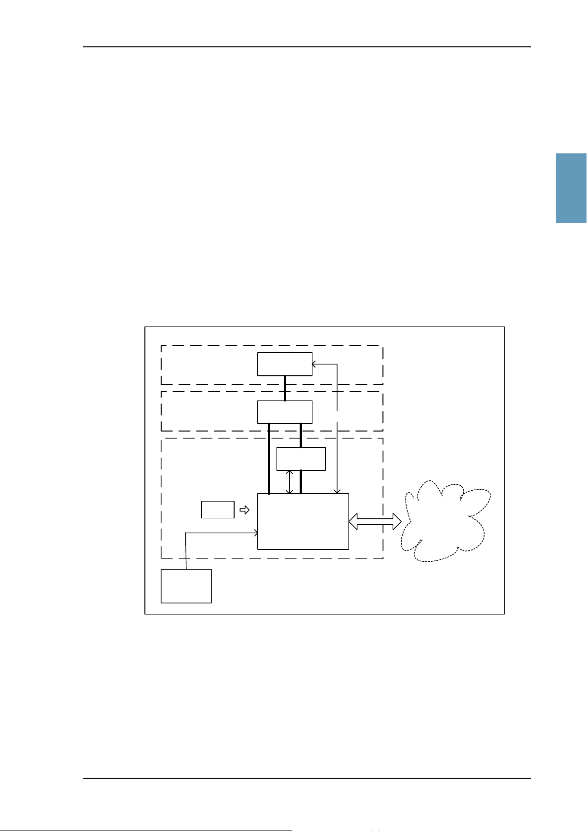
2.3.2 HGA-7000 High Gain Antenna
The Aero-HSD+ system has built-in antenna control (ACU/BSU) for the
electronically steered HGA-7000 antenna.
2222
System Block Diagrams
HGA-7000
TT-5012A
Aero-HSD
IRS /
AHRS
+
CM
Figure 2-1: System Configuration with Electronically Steered HGA
Antenna
DLNA
Rx
GPS
HPA
Tx
SDU
User
Interfaces
TT98-113625-D Chapter 2: Introduction to Aero-HSD
+
2-9
Page 30
System Block Diagrams
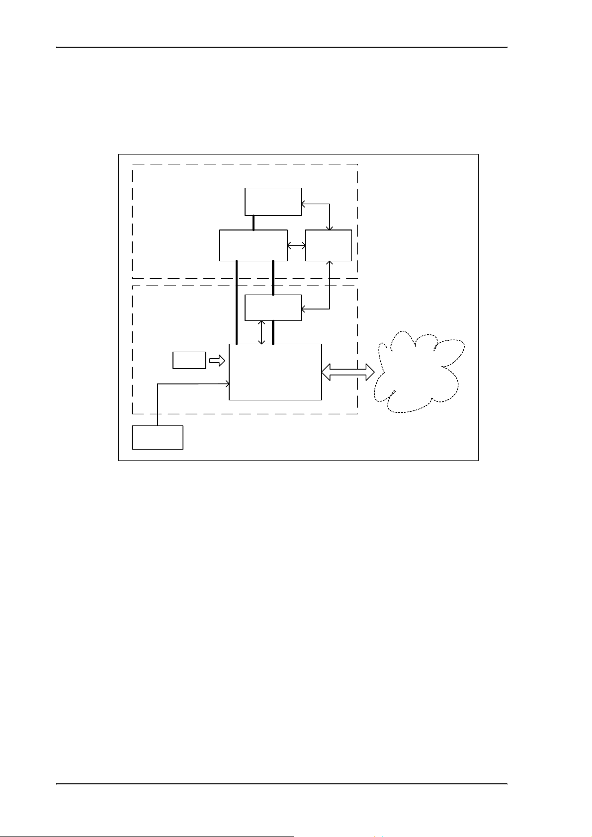
2.3.3 ARINC 741 Compatible High Gain Antenna
The Aero-HSD+ system also supports ARINC 741 compatible antenna systems,
such as the mechanically steered AMT-50 subsystem.
ARINC741 Antenna Subsystem
Antenna
ACU/
BSU
Aero-HSD
ARINC741
DLNA
+
HPA
TxRx
CM
SDU
Interfaces
IRS
Figure 2-2: System Configuration with ARINC 741 Compatible HGA
User
2-10 Chapter 2: Introduction to Aero-HSD
+
TT98-113625-D
Page 31

2222
System Block Diagrams
2.3.4 Dual Side Panel Antenna System (Future Use)
An ARINC 741 dual side panel antenna system may be installed, in order to
improve the view to the satellite.
ARINC 741 Dual Side Panel Antenna System
HGA
(STBO)
BSU
(STBO)
User
Interfaces
SDU
CM
IRS
(Port)
Combiner
DLNA 2
(STBO)
HPR
Tx Rx
HPA
HGA (Port)
BSU
(Port)
Aero-HSD+ System
Figure 2-3: System Configuration with Dual Side Panel Antenna System (Future Use)
DLNA 1
TT98-113625-D Chapter 2: Introduction to Aero-HSD
+
2-11
Page 32

System Block Diagrams
2.3.5 User Interfaces
The Aero-HSD+ system has the following user interfaces:
• Four 4-wire PBX interfaces, which can be used e.g. for the TT-5620A handset
and TT-5622A cradle.
The TT-5622A cradle has an RJ11 connector to which additional 2-wire
terminals can be connected, e.g. for fax or modem data.
• Two 2-wire POTS interfaces, which can be used for the TT-5621B handset and
TT-5622B cradle or other POTS handsets.
The TT-5622B cradle has an RJ11 connector to which additional 2-wire
terminals can be connected, e.g. for fax or modem data.
• MPDS via RS-422 or 10BaseT Ethernet interface.
• Euro ISDN S-bus interface for PC, Fax or STE
• ARINC 429 interfaces for e.g. CMU/ACARS or MCDU/FMS.
• Discrete outputs for annunciators.
The following drawing shows most of the possible user interfaces.
4-W Cradle 4-W Handset
4-W Cradle 4-W Handset
4-W Cradle
4-W Cradle 4-W Handset
4-wire
4-W Handset
TT-5035A SDU
2-W Cradle
2-W Cradle
G3 Fax
Laptop/PC
STU
2-wire / RJ-11
RS-422/
Ethernet
ISDN
ARINC 429
Discrete
Outputs
2-W Phone
2-W Phone
LAN
IP ROUTER
G4 Fax
Laptop/PC
Video Ph.
STE
Annunciators
PC #1
PC #2
PC #3
CMU
AFIS
ACARS
MCDU/FMS
Figure 2-4: System Configuration with Different User Interfaces
2-12 Chapter 2: Introduction to Aero-HSD
+
TT98-113625-D
Page 33

2.3.6 MagnaStar® System
The MagnaStar system is a terrestrial-based telephone system that can be
connected to the 4-wire interfaces of the Aero-HSD+ system.
The connections between the SDU and AIU1 and AIU2 are standard 4-wire
WH-10 Interfaces, with one additional discrete interface (Service Unavailable).
Note: The block diagram below is a simplified overview of one of the
MagnaStar systems. For information on the MagnaStar system, refer to
the relevant MagnaStar installation manual.
2222
System Block Diagrams
Aero-HSD+ System
Satcom Service
SDU
Figure 2-5: System Configuration with MagnaStar System
4-Wire
Unavailable
4-Wire
Magnastar System
AIU
AIU
ARTU/TMU
Handset
CDBR-2
Handset
TT98-113625-D Chapter 2: Introduction to Aero-HSD
+
2-13
Page 34

Operation Overview
2.4 Operation Overview
Note: The Aero-HSD+ system should not be used during take-off and landing.
2.4.1 Configuration
The main configuration tool for the Aero-HSD+ system is the HSD+
Configuration Program (HSD+CP), which can be launched from a standard PC
connected to the front connector of the SDU.
For further information, see HSD+ Configuration Program on page 6-1.
2.4.2 User Interface
The Aero-HSD+ System uses the 4-wire handset as the main interface between the
operator and the system. The display and keypad of the handset give access to the
menu system.
Refer to the Aero-HSD+ User Manual for operating procedures. The Aero-HSD+
User Manual introduces and explains system capabilities and features, handset
controls and functions, placing and receiving calls, and use of the menu system.
2-14 Chapter 2: Introduction to Aero-HSD
+
TT98-113625-D
Page 35

3333
Chapter 3
Equipment Drawings 3
3.1 Introduction
The following pages show copies of mechanical drawings of important system
units relevant for an installation.
IMPORTANT NOTE
The drawings in this manual are for reference only. Contact Thrane & Thrane to
obtain the latest version of the outline drawings.
TT98-113625-D 3-1
Page 36

TT-5035A Satellite Data Unit
3.2 TT-5035A Satellite Data Unit
Figure 3-1: Outline Drawing: Satellite Data Unit
3-2 Chapter 3: Equipment Drawings TT98-113625-D
Page 37

TT-5035A Satellite Data Unit
3.2.1 TT-5035A-001 Configuration Module
3333
Figure 3-2: Outline Drawing: Configuration Module
TT98-113625-D Chapter 3: Equipment Drawings 3-3
Page 38

TT-5014A High Power Amplifier
3.3 TT-5014A High Power Amplifier
Figure 3-3: Outline Drawing: High Power Amplifier
3-4 Chapter 3: Equipment Drawings TT98-113625-D
Page 39

3333
TT-5012A Diplexer Low Noise Amplifier
3.4 TT-5012A Diplexer Low Noise Amplifier
Figure 3-4: Outline Drawing: Diplexer and Low Noise Amplifier
TT98-113625-D Chapter 3: Equipment Drawings 3-5
Page 40

TT-5038A High Speed Data Unit (Optional)
3.5 TT-5038A High Speed Data Unit (Optional)
Figure 3-5: Outline Drawing: High Speed Data Unit
3-6 Chapter 3: Equipment Drawings TT98-113625-D
Page 41

3333
TT-5038A High Speed Data Unit (Optional)
3.5.1 TT-5038A-002 Tx Coupler for Optional HSU
Figure 3-6: Outline Drawing: Tx Coupler for Optional HSU
TT98-113625-D Chapter 3: Equipment Drawings 3-7
Page 42

TT-5038A High Speed Data Unit (Optional)
3.5.2 TT-5038A-003 Rx Power Splitter for Optional HSU
Note: If the Rx Power Splitter is to be mounted on a flat surface, mount it on a
3 mm mounting plate to provide enough space for mounting of the
connectors. For further information see Rx Power Splitter on page 5-5.
Figure 3-7: Outline Drawing: Rx Power Splitter for Optional HSU
3-8 Chapter 3: Equipment Drawings TT98-113625-D
Page 43

3.6 TT-5620A 4-Wire Handset
3333
TT-5620A 4-Wire Handset
Figure 3-8: Outline Drawing: 4-Wire Handset
TT98-113625-D Chapter 3: Equipment Drawings 3-9
Page 44

TT-5622A 4-Wire Cradle
3.7 TT-5622A 4-Wire Cradle
Figure 3-9: Outline Drawing: 4-Wire Cradle
3-10 Chapter 3: Equipment Drawings TT98-113625-D
Page 45

3.8 TT-5621B 2-Wire Handset
3333
TT-5621B 2-Wire Handset
Figure 3-10: Outline Drawing: 2-Wire Handset
TT98-113625-D Chapter 3: Equipment Drawings 3-11
Page 46

TT-5622B 2-Wire Cradle
3.9 TT-5622B 2-Wire Cradle
Figure 3-11: Outline Drawing: 2-Wire Cradle
3-12 Chapter 3: Equipment Drawings TT98-113625-D
Page 47

3.10 SDU and HPA Tray
3333
SDU and HPA Tray
Figure 3-12: Outline Drawing: Tray for SDU and HPA.
TT98-113625-D Chapter 3: Equipment Drawings 3-13
Page 48

SDU Tray Connector
3.11 SDU Tray Connector
Figure 3-13: SDU Tray Connector: ITT Cannon DPX2NA-67322-463
3-14 Chapter 3: Equipment Drawings TT98-113625-D
Page 49

3333
SDU Tray Connector
Figure 3-14: Contact Assembly: Quadrax Pin size 5 special: ITT Cannon 244-0011-001
TT98-113625-D Chapter 3: Equipment Drawings 3-15
Page 50

HPA Tray Connector
3.12 HPA Tray Connector
Figure 3-15: HPA Tray Connector
3-16 Chapter 3: Equipment Drawings TT98-113625-D
Page 51

3.13 HSU Tray
3333
HSU Tray
Figure 3-16: Outline Drawing: Tray for HSU
TT98-113625-D Chapter 3: Equipment Drawings 3-17
Page 52

HSU Tray Connector
3.14 HSU Tray Connector
Figure 3-17: HSU Tray Connector, page 1 of 2
3-18 Chapter 3: Equipment Drawings TT98-113625-D
Page 53

3333
HSU Tray Connector
Figure 3-18: HSU Tray Connector, page 2 of 2
TT98-113625-D Chapter 3: Equipment Drawings 3-19
Page 54

HSU Tray Connector
3-20 Chapter 3: Equipment Drawings TT98-113625-D
Page 55

4444
Chapter 4
Connectors and Pin-out 4
4.1 TT-5035A Satellite Data Unit
4.1.1 Connectors on SDU
There are three connectors on the SDU:
• Maintenance (front connector):
Interface to PC and Handset for maintenance purposes.
A 15 pin Female Sub-D Filter connector
• ARINC 404 (rear connector):
Interfaces to Aircraft and SATCOM interconnections.
An ARINC 404 Shell Size 2 Receptacle.
• Configuration Module (rear, inside connector):
A 9 pin Sub-D Female Connector. This is an internal connector used only as
interface to the Configuration Module.
TT98-113625-D 4-1
Page 56

TT-5035A Satellite Data Unit
4.1.2 SDU Front Connector
Connector Drawing
1
9
15
8
Figure 4-1: SDU Front Connector,
Face View of Engaging End. (DB15F)
Functions
The front connector is a 15 pin Female Sub-D Filter connector, and contains the
following interfaces:
• EIA/TIA-232-E PC port
• 4-Wire Thrane & Thrane Handset
• RS-485 Data interface for T&T Handset
• +12 V DC for powering the Handset
• Write Enable Input for Configuration Module.
4-2 Chapter 4: Connectors and Pin-out TT98-113625-D
Page 57

Pin-out for SDU Front Connector
Pin. No. Pin Name
FP1 Maintenance Handset Audio In Hi
FP2 Maintenance Handset Audio In Lo
FP3 Maintenance Handset Audio Out Hi
FP4 Maintenance Handset Audio Out Lo
FP5 Signal Ground SGND
FP6 Maintenance Handset RS-485 Data A
FP7 Maintenance Handset RS-485 Data B
FP8 +12 V DC/120 mA
4444
TT-5035A Satellite Data Unit
FP9 GND, Power Return (for +12 V DC)
FP10 PC EIA/TIA-232-E RxD Output
FP11 PC EIA/TIA-232-E TxD Input
FP12 PC EIA/TIA-232-E CTS Output
FP13 PC EIA/TIA-232-E RTS Input
FP14 GND
FP15 Configuration Module Write Enable In
Table 4-1: Pin-out for SDU Front Connector
TT98-113625-D Chapter 4: Connectors and Pin-out 4-3
Page 58

TT-5035A Satellite Data Unit
4.1.3 SDU Rear Receptacle
Connector Drawing
Quadrax Ethernet Insert
in A3
SDU Rear Receptacle Mating Plug in Tray
34
12
41
75
13 8
18 14
24 19
29 25
A1A2
A3A4
Top Plug (TP) Insert
A1 A2
A3 A4
Index Pin Code 04
Light areas are key holes
106
79
52
25 13
12
94
67
40
1
Bottom Plug (BP) Insert
94
67
40
112
View: Engaging End
Figure 4-2: SDU Rear Receptacle and Mating Plug in Tray, Engaging End
41
75
138
1814
2419
2925
106
79
52
2513
4-4 Chapter 4: Connectors and Pin-out TT98-113625-D
Page 59

Functions, Top Plug
The Top Plug (TP) connects the following signals:
Power, RF Interfaces and Antenna Modem:
• +28 V DC Power + chassis ground
• +28 V DC/600 mA 4-wire handset supply
• Remote ON/OFF (nON)
• RF Tx signal to HPA
• RF Rx signal from DLNA
• Antenna Modem Interface
Handset interfaces (analog):
4444
TT-5035A Satellite Data Unit
• 4 analog four wire interfaces for Thrane & Thrane Handsets Systems (incl.
+28 V DC Handset supply with nON/OFF power supply control)
Voice/Fax/Modem interfaces:
• 2 VOICE/FAX/MODEM/STU-III, analog 2-wire standard POTS interfaces
TT98-113625-D Chapter 4: Connectors and Pin-out 4-5
Page 60

TT-5035A Satellite Data Unit
Functions, Bottom Plug
The Bottom Plug connects the following signals:
Aircraft Avionics Interfaces:
• 24 bit discrete hardwire strapped ICAO address
• 2 high speed ARINC 429 Inertial Reference System (IRS) or
• 2 high or low speed ARINC 429 Attitude and Heading Reference System
(AHRS)
• 2 high or low ARINC 429 Communication Management Units (ACARS/CMU)
• 2 low speed ARINC 429 Cabin Packet-mode Data Function (CPDF)
• 3 high or low speed ARINC 429 MCDU/FMS (1 output, 2 inputs) or 1 high or
low speed ARINC 429 AES ID input (ICAO address, for future use)
• 2 Discrete inputs for “Weight On Wheels”
• Discrete Inputs/Outputs for WH-10/MagnaStar AIU control or, for future use,
Cockpit Voice
High Speed Interfaces:
• 1 MPDS RS-422, with RS-422 CTS/RTS Hardware Handshake
• 1 Euro ISDN S-bus connection
SATCOM Interfaces:
• 1 RS-422 Multi Control HPA Interface (Tx)
• 1 RS-422 BITE/Status HPA Interfaces (Rx)
• 1 Discrete HPA Remote nON/OFF output
Maintenance Interfaces:
• 1 Discrete SDU Hardware Reset
Handset interfaces (digital):
• 4 RS-485 data interfaces for Thrane & Thrane Handsets
Other interfaces:
• 1 RS-422 SIMCARD Reader Interface (future use)
• 3 Annunciators for: “Service Available”, “Call” and “FAX” -annunciator
• 3 ATE pins (Automatic Test Equipment) - not used
4-6 Chapter 4: Connectors and Pin-out TT98-113625-D
Page 61

Pin-out for SDU Rear Receptacle (Top Plug)
4444
TT-5035A Satellite Data Unit
Pin No. Pin Name
TP A1 RF Rx input from DLNA
12 V DC power to DLNA (Coax)
TP A2 RF Tx output to HPA (Coax)
TP A3.1 Tx + 10BaseT Ethernet
(Quadrax pin 1)
TP A3.2 Rx + 10BaseT Ethernet
(Quadrax pin 2)
TP A3.3 Tx - 10BaseT Ethernet
(Quadrax pin 3)
TP A3.4 Rx - 10BaseT Ethernet
(Quadrax pin 4)
TP A4 Antenna Modem Interface (Coax)
TP1 +28 V DC Power
TP2 GND, Power Return
TP3 Chassis Ground and Handset
Power Return
TP4 +28 V DC/600 mA Handset
Supply
TP5 Remote ON/OFF (nON)
TP6 2-Wire Voice/Fax/Modem #5
(Ring)
Pin No. Pin Name
TP12 Handset #1 Audio Out Hi /
(For future use: Cockpit Voice
Audio #1 Out Hi)
TP13 Handset #1 Audio Out Lo /
(For future use: Cockpit Voice
Audio #1 Out Lo)
TP14 Not Connected
TP15 Handset #2 Audio In Hi /
(For future use: Cockpit Voice
Audio #2 In Hi)
TP16 Handset #2 Audio In Lo /
(For future use: Cockpit Voice
Audio #2 In Lo)
TP17 Handset #2 Audio Out Hi /
(For future use: Cockpit Voice
Audio #2 Out Hi)
TP18 Handset #2 Audio Out Lo /
(For future use: Cockpit Voice
Audio #2 Out Lo)
TP19 2-Wire Voice/Fax/Modem #5
(Tip)
TP20 AGND
TP21 Handset #3 Audio In Hi
TP7 2-Wire Voice/Fax/Modem #6
(Ring)
TP8 2-Wire Voice/Fax/Modem #6
(Tip)
TP9 Not Connected
TP10 Handset #1 Audio In Hi /
(For future use: Cockpit Voice
Audio #1 In Hi)
TP11 Handset #1 Audio In Lo /
(For future use: Cockpit Voice
Audio #1 In Lo)
Table 4-2: Pin-out for SDU Rear Receptacle (Top Plug)
TT98-113625-D Chapter 4: Connectors and Pin-out 4-7
TP22 Handset #3 audio In Lo
TP23 Handset #3 audio Out Hi
TP24 Handset #3 audio Out Lo
TP25 Do not connect!
(+12 V DC / 25 mA)
TP26 Handset #4 audio In Hi
TP27 Handset #4 audio In Lo
TP28 Handset #4 audio Out Hi
TP29 Handset #4 audio Out Lo
Page 62

TT-5035A Satellite Data Unit
Pin-out for SDU Rear Receptacle (Bottom Plug)
Pin No. Pin Name
BP1 ICAO Address Bit #1 (MSB)
BP2 ICAO Address Bit #2
BP3 ICAO Address Bit #3
BP4 ICAO Address Bit #4
BP5 ICAO Address Bit #5
BP6 ICAO Address Bit #6
BP7 ICAO Address Bit #7
BP8 ICAO Address Bit #8
BP9 ICAO Address Bit #9
BP10 ICAO Address Bit #10
BP11 ICAO Address Bit #11
BP12 ICAO Address Bit #12
BP13 ICAO Address Bit #13
BP14 ICAO Address Bit #14
BP15 ICAO Address Bit #15
Pin No. Pin Name
BP27 Data from primary IRS 429 B /
Data from primary AHRS 429 B
BP28 Data from second. IRS 429 A /
Data from second. AHRS 429 A
BP29 Data from second. IRS 429 B /
Data from second. AHRS 429 B
BP30 Data bus from MCDU / FMS #2 /
AES ID input 429 A (future use)
BP31 Data bus from MCDU / FMS #2 /
AES ID input 429 B (future use)
BP32 Data bus from CPDF #1 429 A/
HSU control input
BP33 Data bus from CPDF #1 429 B/
HSU control input
BP34 Data bus to CPDF #1 429 A/
HSU control output
BP35 Data bus to CPDF #1 429 B/
HSU control output
BP36 Data bus from CPDF #2 429 A
BP16 ICAO Address Bit #16
BP17 ICAO Address Bit #17
BP18 ICAO Address Bit #18
BP19 ICAO Address Bit #19
BP20 ICAO Address Bit #20
BP21 ICAO Address Bit #21
BP22 ICAO Address Bit #22
BP23 ICAO Address Bit #23
BP24 ICAO Address Bit #24
BP25 ICAO Address Common
BP26 Data from primary IRS 429 A /
Data from primary AHRS 429 A
BP37 Data bus from CPDF #2 429 B
BP38 Data bus to CPDF #2 429 A
BP39 Data bus to CPDF #2 429 B
BP40 Data bus from
ACARS/CMU #1 429 A
BP41 Data bus from
ACARS/CMU #1 429 B
BP42 Data bus to
ACARS/CMU #1 & #2 429 A
BP43 Data bus to
ACARS/CMU #1 & #2 429 B
BP44 Data bus from
ACARS/CMU #2 429 A
BP45 Data bus from
ACARS/CMU #2 429 B
4-8 Chapter 4: Connectors and Pin-out TT98-113625-D
Page 63

4444
TT-5035A Satellite Data Unit
Pin No. Pin Name
BP46 Data bus from MCDU /
FMS #1 429 A
BP47 Data bus from MCDU /
FMS #1 429 B
BP48 Data bus to MCDU /
FMS #1 & #2 429 A
BP49 Data bus to MCDU /
FMS #1 & #2 429 B
BP50 Reserved for Weight-On-Wheels
Input #1
BP51 Reserved for Weight-On-Wheels
Input #2
BP52 For future use: CP Voice Chime
Signal Contact #1;
Current from Chime
BP53 For future use: CP Voice Chime
Signal Contact #2;
Current to Chime
BP54 MagnaStar: Satcom Service
Unavailable
BP55 WH-10/MagnaStar:
Hook switch #3
Pin No. Pin Name
BP67 ISDN TxP (d)
BP68 ISDN TxN (e)
BP69 ISDN RxN (f)
BP70 Future use: SIMCARD Reader
Control Output B, RS-422
BP71 Future use: SIMCARD Reader
Control Output A, RS-422
BP72 Future use: SIMCARD Reader Data
Input B, RS-422
BP73 Future use: SIMCARD Reader Data
Input A, RS-422
BP74 Do not connect! (ATE 1)
BP75 Do not connect! (ATE 2)
BP76 Do not connect! (ATE 3)
BP77 SDU Reset, Active Low
BP78 HPA Control Output A, RS-422
BP79 HPA Control Output B, RS-422
BP80 HPA Data/BITE Input A, RS-422
BP81 HPA Data/BITE Input B, RS-422
BP56 HSU disable
BP57 HPA remote nON/OFF output
BP58 MPDS TxD-B RS-422 (I)
BP59 MPDS TxD-A RS-422 (I)
BP60 MPDS RxD-B RS-422 (O)
BP61 MPDS RxD-A RS-422 (O)
BP62 MPDS RTS-B RS-422 (I)
BP63 MPDS RTS-A RS-422 (I)
BP64 MPDS CTS-B RS-422 (O)
BP65 MPDS CTS-A RS-422 (O)
BP66 ISDN RxP (c)
BP82 WH-10/MagnaStar Hook Switch #1
or, for future use, CP Voice Call
Cancel Input #1 (Discrete I)
BP83 WH-10/MagnaStar Ringer Output
A1 or, for future use, CP Voice Mic
On Input #1 (Discrete I/O)
BP84 WH-10/MagnaStar Ringer Output
B1 or, for future use, CP Voice Call
Light Output #1 (Discrete O)
BP85 WH-10/MagnaStar Hook Switch #2
or, for future use, CP Voice Call
Cancel Input #2 (Discrete I)
BP86 WH-10/MagnaStar Ringer Output
A2 or, for future use, CP Voice Mic
On Input #2 (Discrete I/O)
TT98-113625-D Chapter 4: Connectors and Pin-out 4-9
Page 64

TT-5035A Satellite Data Unit
Pin No. Pin Name
BP87 WH-10/MagnaStar Ringer Output
B2 or, for future use, CP Voice Call
Light Output #2 (Discrete O)
BP88 Chime/ Lamps Inhibit Input
(Discrete I)
BP89 WH-10/MagnaStar Ringer Output
A3 or Service Available
Annunciator (Discrete I/O)
BP90 WH-10/MagnaStar Ringer Output
B3
BP91 For future use: CP Voice Chime
Reset Input #1 (Discrete I)
BP92 Call Annunciator (Discrete I/O)
BP93 Fax Annunciator (Discrete Output)
BP94 4-Wire Handset #1
RS-485 Data A
BP95 4-Wire Handset #1
RS-485 Data B
Pin No. Pin Name
BP96 4-Wire Handset #2
RS-485 Data A
BP97 4-Wire Handset #2
RS-485 Data B
BP98 4-Wire Handset #3
RS-485 Data A
BP99 4-Wire Handset #3
RS-485 Data B
BP100 4-Wire Handset #4
RS-485 Data A
BP101 4-Wire Handset #4
RS-485 Data B
BP102 MPDS DTR-B RS-422 (I)
BP103 MPDS DTR-A RS-422 (I)
BP104 MPDS DCD-B RS-422 (O)
BP105 MPDS DCD-A RS-422 (O)
BP106 Port 1 GND
Table 4-3: Pin-out for SDU Rear Receptacle (Bottom Plug)
4-10 Chapter 4: Connectors and Pin-out TT98-113625-D
Page 65

4444
TT-5014A High Power Amplifier
4.2 TT-5014A High Power Amplifier
4.2.1 HPA Rear Receptacle
The HPA has one connector:
An ARINC 404, shell size 2, rear receptacle, used for connection to the antenna
system and the SDU.
Connector Drawing
Functions
HPA Rear Receptacle
Top plug (TP)
Index pin code 08
Light areas are key holes
Bottom plug (BP)
Figure 4-3: HPA Receptacle, Face View of Engaging End. Index Code is 08
The Top Plug connects the following signals:
Mating Plug in Tray
• RF Tx signal to DLNA
• RF Tx signal from SDU
The Bottom Plug connects the following signals:
• +28 V DC Power (Aircraft Power Bus)
• Chassis ground
• ARINC 429 Tx and Rx connections for interfacing to ARINC 741 antennas
• Remote ON/OFF (nON) from SDU
• RS-422 data interface to SDU
TT98-113625-D Chapter 4: Connectors and Pin-out 4-11
Page 66

TT-5014A High Power Amplifier
Pin-out for HPA Receptacle
Top P i n Pin Name
TP1 RF Tx output to DLNA
TP2 RF Tx input from SDU
Table 4-4: Pin-out for HPA Receptacle (Top Plug)
Bottom
Pin
Pin Name
BP A1 +28 V DC Power
BP A2 GND, Power Return
BP1 ATE 1
BP2 ATE 2
BP3 ATE 3
BP4 ATE 4
BP5 Spare
BP6 nON
BP7 Spare
BP8 A429 Tx A
BP9 A429 Tx B
BP10 A429 Tx A
BP11 A429 Tx B
BP12 Spare
BP13 A429 Rx1 A
Bottom
Pin
Pin Name
BP17 HPA Mute 1 A
BP18 HPA Mute 1 B
BP19 HPA Mute 2 A
BP20 HPA Mute 2 B
BP21 Spare
BP22 Spare
BP23 Spare
BP24 Spare
BP25 RS-422 Tx A, HPA
Data/BITE Output A,
from HPA to SDU
BP26 RS-422 Tx B, HPA
Data/BITE Output B,
from HPA to SDU
BP27 RS-422 Rx A, HPA Control
Input A, from SDU to HPA
BP28 RS-422 Rx B, HPA Control
Input B, from SDU to HPA
BP14 A429 Rx1 B
BP15 A429 Rx2 A
BP29 Spare
BP30 Chassis
BP16 A429 Rx2 B
Table 4-5: Pin-out for HPA Receptacle (Bottom Plug)
4-12 Chapter 4: Connectors and Pin-out TT98-113625-D
Page 67

4.3 TT-5038A HSU (Optional)
4.3.1 Connectors on HSU
There are two connectors on the HSU:
• Maintenance (front connector):
Interface to PC for maintenance purposes.
A 9 pin female Sub-D connector.
• ARINC 404 (rear connector):
Interfaces to Aircraft and SATCOM interconnections.
An ARINC 404 Shell Size 2 Receptacle.
4.3.2 HSU Front Connector
4444
TT-5038A HSU (Optional)
Connector Drawing
Figure 4-4: HSU Front Connector.
Face View of Engaging End.
Functions
The front connector is a 9 pin Female Sub-D connector, and contains the
following interfaces:
• EIA/TIA-232-E port for #1 RS-232 PC interface
• #2 I/F Disable Input
1
6
9 pin
SUB-D
9
5
female
TT98-113625-D Chapter 4: Connectors and Pin-out 4-13
Page 68

TT-5038A HSU (Optional)
Pin-out for HSU Front Connector
Pin no. Pin Name
FP1 Not used
FP2 #1 RxD Output (EIA/TIA-232-E)
FP3 #1 TxD Input (EIA/TIA-232-E)
FP4 #2 I/F Disable Input
FP5 #1 GND (EIA/TIA-232-E)
FP6 #1 +12 V DC (to pull up FP4)
FP7 Not Used
FP8 Not Used
FP9 Not used
Table 4-6: Pin-out for HSU Front Connector
4.3.3 HSU Rear Receptacle
Connector Drawing
HSU Rear Receptacle
41
75
13 8
18 14
24 19
29 25
A1A2
A3A4
Top Plug (TP) Insert
Index Pin Code 04
Light areas are key holes
Bottom Plug, Blind
Mating Plug in Tray
41
A1 A2
A3 A4
75
138
1814
2419
2925
View: Engaging End
Figure 4-5: HSU Rear Receptacle and Mating Plug in Tray, Engaging End.
4-14 Chapter 4: Connectors and Pin-out TT98-113625-D
Page 69

Functions
4444
TT-5038A HSU (Optional)
The Top Plug of the HSU rear receptacle connects the following signals:
Power & RF Interfaces:
• +28 V DC and chassis ground
• RF Tx signal to HPA
• RF Rx signal from DLNA
User Interfaces:
• MPDS, 10BaseT Ethernet
• MPDS, EIA/TIA-232 with CTS/RTS Hardware Handshake
• Euro ISDN S-bus connection
Control & Maintenance Interfaces:
• EIA/TIA-232 PC interface (#2)
• ARINC 429 High Speed HSU Control Interface
• HSU Failure Discrete Output
• 1 MPDS Service Available Output
• 1 ISDN Service Available Output
• HSU Disable Discrete Input
• 2 ATE Discrete inputs
TT98-113625-D Chapter 4: Connectors and Pin-out 4-15
Page 70

TT-5038A HSU (Optional)
Pin-out for HSU Rear Receptacle
Pin Function
TP A1 RF Rx input from DLNA
TP A2 RF Tx output to HPA
TP A3 10BaseT Rx output
(Center: RxD+)
TP A4 10BaseT Tx input
(Center: TxD+)
TP1 +28 V DC Power
TP2 GND, Power Return
TP3 Chassis Ground
TP4 Not Used
TP5 #2 GND (EIA/TIA-232-E)
TP6 #2 TxD Input
(EIA/TIA-232-E)
TP7 #2 RxD Output
(EIA/TIA-232-E)
Pin Function
TP15 MPDS DTR Input
(EIA/TIA-232-E)
TP16 MPDS DCD Output
(EIA/TIA-232-E)
TP17 MPDS DSR Output
(EIA/TIA-232-E)
TP18 MPDS GND
(EIA/TIA-232-E)
TP19 Data bus output to SDU
(ARINC 429-A)
TP20 Data bus output to SDU
(ARINC 429-B)
TP21 Data bus input from SDU
(ARINC 429-A)
TP22 Data bus input from SDU
(ARINC 429-B)
TP23 ISDN Rx+ (c) input
TP8 HSU Disable, Discrete Input
TP9 ATE #1, Discrete Input
TP10 ATE #2, Discrete Input
TP11 MPDS TxD Input
(EIA/TIA-232-E)
TP12 MPDS RxD Output
(EIA/TIA-232-E)
TP13 MPDS RTS Input
(EIA/TIA-232-E)
TP14 MPDS CTS Output
(EIA/TIA-232-E)
Table 4-7: Pin-out for HSU Rear Receptacle
TP24 ISDN Tx+ (d) output
TP25 ISDN Tx- (e) output
TP26 ISDN Rx- (f) input
TP27 HSU Failure, Discrete Output
(Lamp Type)
TP28 ISDN Service Available,
Discrete Output (Lamp Type)
TP29 MPDS Service Available,
Discrete Output (Lamp Type)
4-16 Chapter 4: Connectors and Pin-out TT98-113625-D
Page 71

4.4 Cradle Connectors
4.4.1 Connectors on 4-Wire Cradle
There are four connectors on the 4-wire cradle, two on the side of the cradle and
two at the end:
4-Wire Handset Connection
4444
Cradle Connectors
Figure 4-6: 4-Wire Cradle Connectors, End View of Cradle
Headset Connection
Figure 4-7: 4-Wire Cradle Connectors, Side View of Cradle
SDU Connection
2-Wire Voice/Fax/Modem Connection
TT98-113625-D Chapter 4: Connectors and Pin-out 4-17
Page 72

Cradle Connectors
4.4.2 4-Wire Connector to SDU
Connector Drawing
DB15 Male
1
9
15
8
View: Solder side
Functions
Figure 4-8: 4-Wire Cradle Connector
(DB15M). View: Solder Side
The 15 pin Sub-D male connector on the “pigtail” at the end of the 4-wire cradle
connects the following signals on the SDU:
Handset interface (analog):
• analog 4-wire interface (incl. +28 V DC Handset supply)
Handset interface (digital):
• RS-485 data interface
Voice/Fax/Modem interface:
• Voice/Fax/Modem/STU-III, analog 2-wire standard POTS interface
OR
Maintenance handset interface:
• Maintenance 4-wire handset connection to SDU front connector
4-18 Chapter 4: Connectors and Pin-out TT98-113625-D
Page 73

Pin-out for DB15 Connector
The 4-wire cradle connector for connection to the SDU has the following pin-out:
4444
Cradle Connectors
Pin Function
12 wire Tip
(Fax/PC_modem/Auxiliary)
22 wire Ring
(Fax/PC_modem/Auxiliary)
3GND
4+28VDC
5 GND, Power Return
6 SDU Audio in +
7 SDU Audio in -
Table 4-8: Pin-out for 15 Pin Sub-D Male Connector on “pigtail” in 4-Wire Cradle
Pin Function
8 GND
9 GND
10 RS-485 Data A
11 RS-485 Data B
12 GND
13 SDU Audio out +
14 SDU Audio out -
15 NC
TT98-113625-D Chapter 4: Connectors and Pin-out 4-19
Page 74

Cradle Connectors
4.4.3 Connectors on 2-Wire Cradle
There are three connectors on the 2-wire cradle, one at the side and two at the end:
2-Wire Handset Connection
SDU Connection
Figure 4-9: 2-Wire Cradle Connectors, End View of Cradle
2-Wire VoiceFax/Modem Connection
Figure 4-10: 2-Wire Cradle Connectors, Side View of Cradle
4-20 Chapter 4: Connectors and Pin-out TT98-113625-D
Page 75

4.4.4 2-Wire Connector to SDU
Connector Drawing
DB9 Male
1
6
9
5
View: Solder side
Figure 4-11: 2-Wire Cradle Connector
(DB9M). View: Solder Side
4444
Cradle Connectors
Functions
The 9 pin Sub-D male connector on the “pigtail” at the end of the 2-wire cradle
connects the following signals on the SDU:
• Voice/Fax/Modem/STU-III, analog 2-wire standard POTS interface
Pin-out for Cradle Connector
The 2-wire cradle connector for connection to the SDU has the following pin-out:
Pin Function
1 Auxiliary Tip
2 Auxiliary Ring
3Shield
4NC
5NC
6NC
7NC
8NC
9NC
Table 4-9: Pin-out for 9 Pin Sub-D Male
Connector on “pigtail” in 2-Wire Cradle.
TT98-113625-D Chapter 4: Connectors and Pin-out 4-21
Page 76

Mating Connectors in Aircraft
4.5 Mating Connectors in Aircraft
Connection With SDU
The installation tray for the SDU is equipped with the following connector:
Connector Mating Connector Type
Front Panel Connector 15 pin SUB-D male
Rear I/O Connector ARINC 404 shell size 2 plug,
with the following contact arrangements:
Internal connector for
Configuration Module
Table 4-10: Mating Connectors in Aircraft for SDU
Insert A
(Top Plug): 33C4
• 4 #16 pin socket contacts
• 25 #20HD socket contacts
• 3 #5 coax socket contacts
• 1 #5 Quadrax socket contact
Insert B (Bottom Plug): 106
• 106 #22 pin contacts
ITT Cannon Part number DPX2NA-67322-463
9-pin SUB-D male
4-22 Chapter 4: Connectors and Pin-out TT98-113625-D
Page 77

Connection With HPA
The installation tray for the HPA is equipped with the following connector:
Connector Mating Connector Type
Rear I/O Connector ARINC 404 shell size 2 plug,
4444
Mating Connectors in Aircraft
with the following contact arrangements:
Table 4-11: Mating Connector in Aircraft for HPA
Connection With Optional HSU
The installation tray for the HSU is equipped with the following connector:
Connector Mating Connector Type
Front Panel Connector 9 pin SUB-D male
Insert A
• 2 #1 coax socket contacts for RG142B
Insert B (Bottom Plug): 32C2
• 2 #5 socket contacts for AWG 8-10
• 30 #20 HD socket contacts for AWG 20-24
Radiall part number 616 697 173
(Top Plug): MC2
Rear I/O Connector ARINC 404 shell size 2 plug with the following
contact arrangements:
Insert A
• 4 #16 socket contacts
• 25 #20 socket contacts
• 2 #5 coax socket contacts
• 2 #5 Twinax socket contacts
Insert B (Bottom Plug): Blind
• Not used
ECS part number DSXN2PS33C45X00500
Table 4-12: Mating Connectors in Aircraft for HSU
(Top Plug): 33C4
TT98-113625-D Chapter 4: Connectors and Pin-out 4-23
Page 78

Mating Connectors in Aircraft
4-24 Chapter 4: Connectors and Pin-out TT98-113625-D
Page 79

5555
Chapter 5
Installation 5
5.1 General
5.1.1 Overview
This chapter contains considerations and recommendations for installation of the
Aero-HSD
satisfy all applicable regulations.
Note: Complete installation kits including wiring can be obtained through ECS
The Installation chapter is organized in the following sections:
• Mounting Considerations on page 5-4.
This section provides guidelines for the mechanical installation of the units in
the Aero-HSD+ system.
• Electrical Installation and Wiring on page 5-7.
This section provides wiring drawings and guidelines for the electrical
installation of the Aero-HSD+ system. It also lists the requirements to the
cables.
• Electrical Installation and Wiring, HSU on page 5-63.
This section provides wiring drawings and guidelines for the electrical
installation of the Aero-HSD
requirements to the cables.
+
System. Interconnect harness wiring and physical mounting must
(Electronic Cable Specialists, Inc.). For information, contact
ECS, USA
Phone: +1 414.421.5300
Email: sales@ecsdirect.com
Homepage: www.ecsdirect.com
+
system with an HSU installed. It also lists the
• Recommended Cables on page 5-81.
This section provides lists of recommended cables and maximum cable lengths.
The information, drawings and wiring diagrams contained in this manual are
intended as a reference for engineering planning only. The drawings and wiring
diagrams contained herein do not represent any specific STC. It is the installer’s
responsibility to compose installation drawings specific to the aircraft. This
manual and the drawings and wiring diagrams contained herein may not be used
as a substitute for an STC.
Note: To ensure optimal performance from the Aero-HSD
adherence to the installation considerations found in this section must be
maintained.
TT98-113625-D 5-1
+
System, strict
Page 80

General
5.1.2 Minimum System
A minimum working system has at least:
• one TT-5035A SDU
• one TT-5035A-001 CM
• one TT-5014A HPA
• one handset and cradle, e.g. a TT-5620A 4-Wire Handset and a TT-5622A 4Wire Cradle.
• one antenna system. As antenna system, use either the AMT-50 Antenna
Subsystem or the HGA-7000 Antenna with a TT-5012A DLNA.
The following drawing shows the minimum installation required in the
Aero-HSD+ system.
5-2 Chapter 5: Installation TT98-113625-D
Page 81

Minimum System Drawing
Note: This drawing is an overview of which units to connect as a minimum. For
specific information on wiring, refer to the appropriate section of
Electrical Installation and Wiring on page 5-7 onwards.
5555
General
28 V DC
Aircraft
Power Supply
28 V DC
Aircraft
Power Supply
BP A1 +28 V DC Power
BP A2 GND, Power Return
BP30 Chassis
BP27
HPA CONTROL
BP78
TP1 +28 VDC Power
TP2 GND, Power Return
TP3
Chassis Ground and Handset Power Return
Remote ON/OFF (nON)
TP5
TT-5014A
HPA
BP28
BP25
BP26
BITE / STATUS
BP79
BP80
BP81
TP2
BP6
RF Tx
HPA nON
BP57
TP A2
TT-5035A
SDU
Chassis Ground and Handset Power Return
Handset #1 Audio Out / Cockpit Voice A udio Out
Handset #1 Audio In / Cockpit Voice Audi o In
Two-wire fax/modem
Full Feature Handset #1 RS-485 Data
+28 VDC / 600mA Handset Supply
TP1
Built-in
BSU
Tip
Ring
A BP94
B BP95
Hi TP12
Lo TP13
Hi TP10
Lo TP11
TP A4
TP19
TP6
TP4
TP3
RF Tx
TP A1
RF Rx
GND
X3 TX
TT-5012A
X1 RX
X2 Ant
J1 IF1
HGA-7000
J2 IF2
1
1
2
2
9
9
10
10
11
11
3
3
4
4
5
5
12
12
13
13
14
14
6
6
7
7
8
8
15
NC
15
DLNA
TT-5622A
CRADLE
TT-5620A
HANDSET
#1
IRS/AHRS A429 A, BP26
BP1 ICAO MSB
BP2
BP3
BP4
BP5
BP6
BP7
BP8
BP9
BP10
BP11
BP12
BP13
BP14
BP15
BP16
BP17
BP18
BP19
BP20
BP21
BP22
BP23
BP24 ICAO LSB
BP25 ICAO common
IRS/AHRS A429 B, BP27
IRS/AHRS
Strapped ICAO Address
Figure 5-1: Minimum System
Note: This example includes an HGA-7000 Antenna with a TT-5012A DLNA,
but the antenna system may as well be e.g. an AMT-50 subsystem.
Note: Another type of 4-wire handset or a 2-wire handset may be connected
instead of the Thrane & Thrane 4-wire handset.
TT98-113625-D Chapter 5: Installation 5-3
Page 82

Mounting Considerations
5.2 Mounting Considerations
5.2.1 Overview
For optimum system performance, some guidelines on where to install or mount
the different components of the Aero-HSD+ System must be followed. Mounting
and placement details are included in this section.
For information on requirements to cables, see the individual sections in
Electrical Installation and Wiring on page 5-7 or Electrical Installation and
Wiring, HSU on page 5-63.
For information on recommended cable types and lengths, see Recommended
Cables on page 5-81.
Note: When mounting the units, make sure that there is enough space to
provide a sufficient bend radius for the cables. See the cable data sheet
for minimum bend radius.
5.2.2 SDU
Forced cooling is not recommended for the SDU.
• Place the SDU in a temperature controlled area (e.g. avionics bay).
• Place the SDU where the cooling air holes are not blocked. Note that cooling
air holes in the SDU are placed outside the recommended area for
ARINC 404A 3/8 ATR short units.
• Mount the SDU in an ARINC 404A 3/8 ATR short standard tray.
5.2.3 HSU
Forced cooling is not recommended for the HSU.
• Place the HSU in a temperature controlled area (e.g. avionics bay).
• Place the HSU where the cooling air holes are not blocked. Note that cooling
air holes in the HSU are placed outside the recommended area for
ARINC 404A 1/4 ATR short units.
• Mount the HSU in an ARINC 404A 1/4 ATR short standard tray.
5-4 Chapter 5: Installation TT98-113625-D
Page 83

5.2.4 Rx Power Splitter
If the Rx Power Splitter is to be mounted on a flat surface, mount it on a 3 mm
mounting plate to provide enough space for mounting of the connectors.
Figure 5-2: Mounting the Rx Power Splitter
5.2.5 HPA
5555
Mounting Considerations
The HPA can be installed in a non-temperature controlled area.
The HPA is designed with built-in forced cooling (fans).
Internal temperature monitoring prevents damage caused by overheating.
Important! Respect the minimum clearance of 25 mm from top and bottom.
• Mount the HPA vertically on a panel to ensure maximum cooling. Mount the
HPA in an ARINC 404A 3/8 ATR short tray with oval cut-out as shown in
Figure 3-12: Outline Drawing: Tray for SDU and HPA.
• Install the HPA as close to the DLNA as possible.
The cable between the HPA and the DLNA must be a special low-loss coax
cable. See Wiring Antenna Systems on page 5-14 and the wiring drawings
Figure 5-5: Wiring HGA-7000 Antenna and TT-5012A DLNA and Figure
5-6: Wiring AMT-50 Subsystem.
5.2.6 DLNA
The DLNA can be installed in a non-temperature controlled area. The DLNA can
be mounted in an upright position.
• Install the DLNA as close to the antenna as possible.
• Place the DLNA with sufficient contact to the surface, respecting the max.
resistance of 3 mΩ. The DLNA can be mounted on a shelf or directly on the
fuselage.
Important! If the DLNA is mounted directly on fuselage, mount with
Cadmium plated washers between the DLNA and fuselage.
The coax cable between the DLNA and the antenna must be a low-loss coax cable.
See Wiring Antenna Systems on page 5-14 for requirements to the cable.
TT98-113625-D Chapter 5: Installation 5-5
Page 84

Mounting Considerations
5.2.7 Antenna
General Mounting Considerations
Refer to the antenna manual for details on mounting the antenna. Make sure all
requirements in the antenna mounting instructions are met.
Place the antenna with unobstructed view to the satellite.
WARNING! Respect a safety distance of minimum 6.6 feet (2 metres) of the
antenna when the system is transmitting, unless the antenna manual
or the specific system configuration presents different
requirements.
Note: The antenna installation must be in accordance with the aircraft
manufacturers requirements and/or FAA AC 43.13 - 1B/2A and
approved by the appropriate Civil Aviation Authorities.
Satcom filter
If the GPS antenna for the existing GPS receiver on board the aircraft does not
provide sufficient filtering it may be necessary to install a Satcom filter for the
GPS antenna.
Cables to the antennas
Be aware that the shorter the cable is, the better the system performance is.
Do not bend the cables to a radius smaller than the minimum bend radius stated
for the cables.
For further information on cables, see Wiring Antenna Systems on page 5-14,
Wiring Antenna Systems With HSU Installed on page 5-65 and
Recommended Cables on page 5-81
5-6 Chapter 5: Installation TT98-113625-D
Page 85

5555
Electrical Installation and Wiring
5.3 Electrical Installation and Wiring
5.3.1 Wiring Symbols
Throughout the wiring section these common symbols are used:
Coax
Shield
Ground
Twisted
Twisted and shielded
TT98-113625-D Chapter 5: Installation 5-7
Page 86

Electrical Installation and Wiring
5.3.2 Wiring Power Supply
Important! Do not use the same 20 A circuit breaker for both the SDU and the
HPA. Use separate circuit breakers as described in this section, and
with the current rating stated here.
Wiring of Satellite Data Unit
The Aircraft Power Bus provides the electric power required to operate the SDU,
and a chassis connection to the aircraft chassis and the installation tray. The
+28 V DC Power wire must include a circuit breaker capable of carrying the
required current continuously under the required environmental conditions.
The following drawing shows the wiring of the SDU power supply.
Requirements to the wiring are stated in the notes on the drawing and in the
section Cable Requirements, SDU Power Supply on page 5-10.
[4]
[3]
20
AWG
[1]
TP1 +28 VDC Power
TP2 GND, Power Return
TP3
Chassis Ground and Handset Power Return
[5]
Remote ON/OFF (nON)
TP5
TT-5035A
SDU
28VDC
Aircraft Power Bus
[1] Total resistance max. 200 mΩ incl. Circuit Breaker.
[2] Total resistance max. 25 mΩ .
[3] Directly to Aircraft chassis, max. 1 m cable length to prevent EMC problems and max. 25 mΩ resistance
[4] Recommended circuit breaker: Klixon 2TC series, 4 A current rating
[5] If SATCOM On/Off switch is required, TP5 is routed to an external switch to ground
4A
[2]
Figure 5-3: Wiring SDU Power Supply
5-8 Chapter 5: Installation TT98-113625-D
Page 87

5555
Electrical Installation and Wiring
The following list shows the pins used for the SDU power supply.
SDU pin Name Description
TP1 +28 V DC Power +28 V DC Power input from Aircraft power bus.
TP2 GND, Power Return Aircraft Ground connection
TP3 Chassis Ground and
Handset Power Return
TP5 Remote ON/OFF (nON) Power On/Off for the SDU and handsets.
Table 5-1: Pins for SDU Power Supply
+28 V DC Power (TP1)
It is essential to keep the line impedance below the specified limits. See Cable
Requirements, SDU Power Supply on page 5-10.
Reverse polarity protection is only guaranteed if the suggested circuit breaker is
used.
Required current capability for the Circuit Breaker: 48 W @ 17.3 V DC which
equals 2.8 A DC at the required environmental conditions.
A suitable circuit breaker would be Klixon 2TC series with 4 A current rating.
Important! Do not use the HPA 20 A circuit breaker for both the HPA and the
SDU.
Chassis Ground / Handset Power Return (TP3)
Chassis connection, connected to installation
tray and Aircraft chassis.
Also used for handset power return.
The Chassis connection makes sure that the HPA cabinet and the installation tray
has the same potential, and that there is a connection from the wiring shields to the
cabinet for EMC purposes.
Connect the wire directly to the installation tray, and to aircraft chassis.
TP3 also connects to the Handset Power Return.
Remote On/Off (nON) input (TP5)
The nON input is used to turn the SDU and the power supply to the handsets on
and off. Connection of this input to ground turns on the SDU and all other units in
the SATCOM system (Handsets, DLNA, HPA and HGA-7000 Antenna).
However, ARINC 741 Antennas and DLNAs are not turned off when the SDU is
turned off.
The electrical specifications are defined like the discrete WOW input type. Please
refer to Discrete type and description: on page 5-57.
TT98-113625-D Chapter 5: Installation 5-9
Page 88

Electrical Installation and Wiring
Cable Requirements, SDU Power Supply
a
Cable
Max. Resistance Other Requirements
[1]
(+28 V DC)
[2]
200 mΩ,
incl. circuit breaker
25 mΩ The cable should be as short as possible.
(GND, Power
Return)
[3]
25 mΩ Connect directly to aircraft chassis.
(Chassis Ground)
Table 5-2: Requirements to SDU Power Cables
a. The cable numbers refer to the numbers stated on the wiring drawing in the section
Wiring of Satellite Data Unit on page 5-8.
Note: Maximum cable lengths are calculated and listed in the section Power
Cables, Allowed Cable Lengths on page 5-81.
5-10 Chapter 5: Installation TT98-113625-D
Page 89

Wiring of High Power Amplifier
The Aircraft power bus provides the electric power required to operate the HPA,
and a chassis connection to the aircraft chassis and the installation tray. The
+28 V DC Power wire must include a circuit breaker capable of carrying the
required current continuously under the required environmental conditions.
The following drawing shows the wiring of the HPA power supply.
Requirements to the wiring are stated in the notes on the drawing and in the
section Cable Requirements, HPA Power Supply on page 5-13.
28 V DC
Aircraft Power Bus
20A
[2]
[4]
5555
Electrical Installation and Wiring
[1]
BP A1 +28 V DC Power
BP A2 GND, Power Return
[3]
BP30 Chassis
TT-5014A
HPA
TT-5035A
SDU
[1] Total resistance max. 100 mΩ incl. Circuit Breaker.
[2] Total resistance max. 25 mΩ.
[3] Directly to Aircraft chassis, max. 0.6 m cable length (AWG 20) to prevent EMC problems and
max. resistance 25 mΩ.
[4] Recommended circuit breaker: Klixon 2TC series, 20 A current rating.
[5] Must be shielded to prevent EMC problems.
BP57
[5]
Figure 5-4: Wiring HPA Power Supply
BP6 nON
TT98-113625-D Chapter 5: Installation 5-11
Page 90

Electrical Installation and Wiring
The following list shows the pins used for the HPA power supply.
HPA pin Name Description
BP A1 +28 V DC Power +28 V DC Power input from Aircraft power bus.
BP A2 GND, Power Return Aircraft ground connection.
BP30 Chassis Chassis connection, connected to installation
BP6 nON HPA power on/off controlled by the SDU.
SDU pin Name Description
BP57 HPA remote nON/OFF output Power On/Off control for the HPA.
Table 5-4: Pin for Remote HPA Power on/off by SDU
tray and Aircraft chassis.
Table 5-3: Pins for HPA Power Supply
This section describes the installation requirements for HPA power supply
interface. The connection from the HPA to the Aircraft power bus normally goes
through the tray connector. The connector also supports other signals. For
information on pin-out, please refer to TT-5014A High Power Amplifier on
page 4-11.
+28 V DC Power
It is essential to keep the line impedance below the specified limits. See Cable
Requirements, HPA Power Supply on page 5-13.
Reverse polarity protection is only guaranteed if the suggested circuit breaker is
used.
Required current capability for the Circuit Breaker: 235 W @ 15.7 V DC, which
equals 15 A DC, at the required environmental conditions.
A suitable circuit breaker would be Klixon 2TC series with 20 A current rating.
Chassis (BP30)
The Chassis connection makes sure that the HPA cabinet and the installation tray
has the same potential, and that there is a connection from the wiring shields to
cabinet for EMC purposes.
Connect the wire directly to the installation tray, and to aircraft chassis.
nON (BP6)
The nON input is used by the SDU (BP57) to turn the HPA on and off. The SDU
connects this input to ground to turn on the HPA.
5-12 Chapter 5: Installation TT98-113625-D
Page 91

Cable Requirements, HPA Power Supply
a
Cable
Max. Resistance Other Requirements
5555
Electrical Installation and Wiring
[1]
(+28 V DC Power)
[2]
(GND, Power Return)
[3]
(Chassis)
[5]
(nON)
a. The cable numbers refer to the numbers stated on the wiring drawing in the section
Wiring of High Power Amplifier on page 5-11.
Note: Maximum cable lengths are calculated and listed in the section Power
Cables, Allowed Cable Lengths on page 5-81.
100 mΩ,
incl. circuit breaker
25 mΩ
25 mΩ Connect directly to aircraft chassis.
- Must be shielded to avoid EMC
problems.
Table 5-5: Requirements to HPA Power Cables
TT98-113625-D Chapter 5: Installation 5-13
Page 92

Electrical Installation and Wiring
5.3.3 Wiring Antenna Systems
Cable Losses
During installation, it is important that you write down the cable losses of the RF
cables. For this purpose, you may use the last part of the check sheet in Pre-
Installation Check on page 7-2.
The cable losses must be registered in the HSD+CP during configuration of the
system. For further information, see Basic Configuration on page 6-6 or the
online help in the HSD+CP.
5-14 Chapter 5: Installation TT98-113625-D
Page 93

Wiring of HGA-7000 Antenna
The following drawing shows the wiring for an Aero-HSD+ system using an
HGA-7000 antenna.
Note: For information on wiring an HGA-7000 Antenna when the TT-5038A
HSU is installed, see HGA-7000 Antenna with HSU on page 5-65.
Requirements to the cables are stated on the drawing and in the section Cable
Requirements, HGA-7000 Antenna on page 5-17.
Built-in
BSU
TT-5035A
SDU
TP A4
TP A1
W5
W7
[2]
5555
Electrical Installation and Wiring
[5]
W3
[3], [4]
J2 IF2
HGA-7000
J1 IF1
X2 Ant
TT-5012A
X1 RX
DLNA
GND
[6]
X3 TX
W4
TP1
BP78
BP79
BP80
BP81
BP57
TP A2
[1] Coax, loss from cable W6 max. 12 dB
[2] Coax, loss from cable W5 max. 15 dB
[3] Coax, total loss from cable W3 and cable W4 max. 1.8 dB
[4] Coax, loss from cable W3 max. 0.3 dB
[5] Coax, loss from cable W7 max. 17 dB
[6] 16 AWG, max. 1 ft long, max. resistance 3 mΩ
HPA CONTROL
DATA / BITE
HPA nON
[1]
W6
BP27
BP28
BP25
TT-5014A
BP26
BP6
TP2
HPA
[3]
Figure 5-5: Wiring HGA-7000 Antenna and TT-5012A DLNA
Important! Remember to write down the cable losses. See Cable Losses on
page 5-14.
TT98-113625-D Chapter 5: Installation 5-15
Page 94

Electrical Installation and Wiring
The following list shows the pins in the Aero-HSD+ system used for connecting
the HGA-7000 antenna.
SDU pin Name/Description
TP A1 RF Rx input from TT-5012A DLNA/12V DC power to DLNA (Coax)
TP A2 RF Tx output to HPA (Coax)
TP A4 Antenna Modem Interface (Coax)
BP57 HPA remote nOn/Off output
BP78 HPA Control Output A, RS-422
BP79 HPA Control Output B, RS-422
BP80 HPA Data/BITE Input A, RS-422
BP81 HPA Data/BITE Input B, RS-422
Table 5-6: SDU Pins for HGA-7000 Antenna
HPA pin Name/Description
TP1 RF output to TT-5012A DLNA (Coax)
TP2 RF input from SDU (Coax)
BP6 Remote nOn/Off input from SDU
BP25 Tx Data/BITE Output A, RS-422, to SDU
BP26 Tx Data/BITE Output B, RS-422, to SDU
BP27 Rx Control Input A, RS-422, from SDU
BP28 Rx Control Input B, RS-422, from SDU
Table 5-7: HPA Pins for HGA-7000 Antenna
5-16 Chapter 5: Installation TT98-113625-D
Page 95

Cable Requirements, HGA-7000 Antenna
The following list shows the cable requirements to the RF cables in the
Aero-HSD+ system when using an HGA-7000 antenna.
5555
Electrical Installation and Wiring
a
Cable
W3
(DLNA-Antenna)
W4
(HPA-DLNA)
W3 and W4 Coax 0 dB Total:
W5
(TT-5012A DLNA
to SDU)
W6
(RF Tx output from
SDU to HPA)
W7
(Antenna modem
interface)
Type
Coax 0 dB 0.3 dB
Coax 0 dB 1.8 dB - W3
Coax 0 dB 15 dB
Coax 0 dB 12 dB
Coax 0 dB 17 dB
Min.
Cable Loss
@1.6 GHz
Max.
Cable Loss
@1.6 GHz
1.8 dB
Other Requirements
GND on DLNA - - - Resistance: Max. 3 mΩ
Table 5-8: Requirements to RF Cables, HGA-7000 Antenna
a. The “W” cable numbers refer to the numbers stated on the wiring drawing in the section
Wiring of HGA-7000 Antenna on page 5-15.
Note: For recommended cable types, see Recommended RF Cables on
page 5-84.
TT98-113625-D Chapter 5: Installation 5-17
Page 96

Electrical Installation and Wiring
Wiring ARINC 741 Antenna Systems
The following drawing shows the wiring for an Aero-HSD+ system using the
AMT-50 antenna subsystem.
Note: For information on wiring an AMT-50 subsystem when the TT-5038A
HSU is installed, see AMT-50 Subsystem With HSU on page 5-69.
Requirements to the cables are stated on the drawing and in the section RF Cable
Requirements, AMT-50 Subsystem on page 5-20.
TP A1
TT-5035A
SDU
BP78
BP79
BP80
BP81
BP57
[2]
W5
HPA CONTROL
DATA / BITE
HPA nON
J2
J3
W4
AMT-50
DLNA
[3]
TP1
BP27
BP28
BP25
BP26
BP6
W3
[3] [4]
J1
AMT-50
ACU
A B G H
)
S
L
(
x
R
9
2
4
A429 Tx (HS)
A
BP8
BP9
BP13
TT-5014A
HPA
AMT-50 Subsystem
AMT-50
Ant.
BP14
[1]
TP A2
W6
TP2
[1] Coax, loss from cable W6 max. 12 dB
[2] Coax, loss from cable W5 min. 6 dB and max. 29 dB
[3] Coax, total loss from cable W3 and cable W4 max. 1.8 dB
[4] Coax, loss from cable W3 max. 0.3 dB
Figure 5-6: Wiring AMT-50 Subsystem
Important! Remember to write down the cable losses. See Cable Losses on
page 5-14.
5-18 Chapter 5: Installation TT98-113625-D
Page 97

5555
Electrical Installation and Wiring
The following list shows the pins in the Aero-HSD+ system used for connecting
the AMT-50 Subsystem.
SDU pin Name/Description
TP A1 RF Rx input from ARINC 741 DLNA (Coax)
TP A2 RF Tx output to HPA (Coax)
BP57 HPA remote nOn/Off output
BP78 HPA Control Output A, RS-422
BP79 HPA Control Output B, RS-422
BP80 HPA Data/BITE Input A, RS-422
BP81 HPA Data/BITE Input B, RS-422
Table 5-9: SDU Pins for AMT-50 Subsystem
HPA pin Name/Description
TP1 RF output to ARINC 741 DLNA (Coax)
TP2 RF input from SDU (Coax)
BP6 Remote nOn/Off input from SDU
BP8 A429 Tx A output to AMT-50 ACU
BP9 A429 Tx B output to AMT-50 ACU
BP13 A429 Rx1 A input from AMT-50 ACU
BP14 A429 Rx1 B input from AMT-50 ACU
BP25 Tx Data/BITE Output A, RS-422, to SDU
BP26 Tx Data/BITE Output B, RS-422, to SDU
BP27 Rx Control Input A, RS-422, from SDU
BP28 Rx Control Input B, RS-422, from SDU
Table 5-10: HPA Pins for AMT-50 Subsystem
TT98-113625-D Chapter 5: Installation 5-19
Page 98

Electrical Installation and Wiring
RF Cable Requirements, AMT-50 Subsystem
The following list shows the cable requirements to the RF cables in the
Aero-HSD+ system when using an AMT-50 antenna subsystem.
a
Cable
W3
(DLNA-Antenna)
W4
(HPA-DLNA)
W3 and W4 Coax 0 dB Total: 1.8 dB
W5
(ARINC 741 DLNA
to SDU)
W6
(RF Tx output from
SDU to HPA)
Table 5-11: Requirements to RF Cables, AMT-50 Subsystem
a. The “W” cable numbers refer to the numbers stated on the wiring drawing
in the section Wiring ARINC 741 Antenna Systems on page 5-18.
Type
Coax 0 dB 0.3 dB
Coax 0 dB 1.8 dB - W3
Coax 6 dB 29 dB
Coax 0 dB 12 dB
Min. Cable Loss
@1.6 GHz
Max. Cable
Loss@1.6 GHz
Note: For recommended cable types, see Recommended RF Cables on
page 5-84.
Cable Requirements, ARINC 429
The cables for the ARINC 429 interfaces must be twisted and shielded and
conform to the standards for aeronautical use.
For recommended cable types, see Recommended Cables for ARINC 429 on
page 5-84.
5-20 Chapter 5: Installation TT98-113625-D
Page 99

Electrical Installation and Wiring
Wiring ARINC 741 Dual Side Panel Antenna System (Future Use)
The following drawing shows the wiring of an ARINC 741 dual side panel
antenna system.
5555
Aero-HSD+ System
A429 Rx1 A, BP13
A429 Rx1 B, BP14
A429 Tx A, BP8
A429 Tx B, BP9
HPA Mute 1 A, BP17
HPA Mute 1 B, BP18
RF Tx output, TP1
TT-5014A
HPA
A429 Rx2 A, BP15
A429 Rx2 B, BP16
A429 Tx A, BP10
A429 Tx B, BP11
HPA Mute 2 A, BP19
HPA Mute 2 B, BP20
ARINC 741 Dual Side Panel Antenna System
W
X
T
U
G
H
BSU
(Port)
Ant
HGA
(Port)
DLNA
(Port)
Tx Rx
[3]
[3]
HPR
[3]
Tx Rx
[2]
Combiner
[2]
DLNA
(STBO)
Ant
W
X
BSU
T
U
(STBO)
G
H
HGA
(STBO)
BP27
BP28
BP25
BP26
BP6
TP2
[1] Coax, loss from cable W6: max. 12 dB
[2] Coax, total loss from each of the DLNAs to the SDU, including loss in
the Combiner: min. 6 dB and max. 29 dB
[3] Coax, total loss from HPA to each of the DLNAs, including loss in the
HPR: max. 1.5 dB, assuming that the total loss from DLNA to antenna is
0.3 dB.
HPA CONTROL
Data/BITE
HPA nON
RF Tx
[1]
W6
BP78
BP79
BP80
TT-5035A
BP81
BP57
TP A2
SDU
TPA1
RF Rx
[2]
Figure 5-7: Wiring ARINC 741 Dual Side Panel Antenna System
TT98-113625-D Chapter 5: Installation 5-21
Page 100

Electrical Installation and Wiring
Important! Remember to write down the cable losses. See Cable Losses on
page 5-14.
The following list shows the pins in the Aero-HSD+ system used for connecting a
Dual Side Panel antenna system.
HPA pin Name/Description
TP1 RF Tx output to HPR (Coax)
TP2 RF Tx input from SDU (Coax)
BP6 Remote nOn/Off input from SDU
BP8 A429 Tx A output to BSU (Port)
BP9 A429 Tx B output to BSU (Port)
BP10 A429 Tx A output to BSU (STBO)
BP11 A429 Tx B output to BSU (STBO)
BP13 A429 Rx1 A input from BSU (Port)
BP14 A429 Rx1 B input from BSU (Port)
BP15 A429 Rx2 A input from BSU (STBO)
BP16 A429 Rx2 B input from BSU (STBO)
BP17 HPA Mute 1 A input from BSU (Port)
BP18 HPA Mute 1 B input from BSU (Port)
BP19 HPA Mute 2 A input from BSU (STBO)
BP20 HPA Mute 2 B input from BSU (STBO)
BP25 Tx Data/BITE Output A, RS-422, to SDU
BP26 Tx Data/BITE Output B, RS-422, to SDU
BP27 Rx Control Input A, RS-422, from SDU
BP28 Rx Control Input B, RS-422, from SDU
Table 5-12: HPA Pins for Dual Side Panel Antenna System
5-22 Chapter 5: Installation TT98-113625-D
 Loading...