

Thought Technology Ltd. Procomp Infiniti Hardware Manual
™
ProComp Infiniti
Hardware Manual
Thought Technology Ltd.
2180 Belgrave Avenue, Montreal, QC H4A 2L8 Canada
Tel: (800) 361-3651 ٠ (514) 489-8251 Fax: (514) 489-8255
mail@thoughttechnology.com
E-mail:
Webpage:
http://www.thoughttechnology.com

ProComp Infiniti Hardware Manual
2

The Manufacturer:
Product Name:
Product #:
Device Name:
Device #:
EC REP
Thought Technology Ltd.
2180 Belgrave Avenue
Montreal, Quebec, Canada
H4A 2L8
ProComp Infiniti System
T7110M, T7120M, T7150M, T7160M,
T7170M, T7500M, T7520M
ProComp Infiniti Encoder
SA7500
EMERGO EUROPE
Molenstraat 15, 2513 BH,
The Hague, The Netherlands
Tel: +31.70.345.8570
Fax: +31.70.346.7299
ProComp Infiniti Hardware Manual
3

CAUTION
WARNING
ATTENTION
Type BF Equipment
•
• Internally powered equipment
• Continuous operation
• Read Instruction Manual
• US Federal Law restricts this device to sale by, or on order of, a physician or any other
practitioner licensed by the law of the state in which he or she practices to use or order the use
of this device.
• Do not operate Active Sensors within 10 feet of an operating cellular phone, similar radio
transmitting device, other powerful radio interference producing sources such as arc welders,
radio thermal treatment equipment, x-ray machines, or any other equipment that produces
electrical sparks.
• All encoders are totally isolated from line (110 or 220VAC) power due to battery operation and
fiber optic connections to computers. However, many hospitals and the FDA require that
computers, printers and any other equipment used with medical devices be electrically isolated
from line voltage to UL or CSA medical safety standards.
• The PC used with ProComp Infiniti must be placed outside the patient/client environment
(more than 3 meters or 10 feet) or the PC must comply with EN60601-1-1 (system safety).
• After use, the Disposable Electrodes may be a biohazard. Handle, and when applicable,
dispose of these materials in accordance with accepted medical practice and any applicable
local, state and federal laws and regulations.
• Reusable electrodes present a potential risk of cross-infection especially when used on
abraded skin, unless they are restricted to a single patient or sterilized between patients. If
sterilizing electrodes, employ only gas sterilization.
• Radiated radio frequency electromagnetic fields can cause performance degradation in the
MyoScan-Pro EMG sensor. In the worst case, an RF field strength of 22mV/M can cause an
increase of 1μV in the signal reading from a MyoScan-Pro sensor. Be sure to keep in mind
that a very relaxed muscle should provide an EMG reading of approximately 1-3μV.
• Explosion Hazard; Do not use in the presence of a flammable anesthetic mixture with air, or
with Oxygen or Nitrous Oxide.
• Not to be immersed in water.
• Take care in arranging patient and sensor cables to avoid risk of patient entanglement or
strangulation.
• The operator is responsible for ensuring the safety of any devices controlled or triggered by
Infiniti equipment or software, or by any software or hardware receiving data from Infiniti
equipment. Infiniti equipment must not be configured or connected in such a way that failure in
its data acquisition, processing or control functions can trigger patient feedback stimulus that
poses an unacceptable level of risk.
• Use of any equipment in a biofeedback context should be immediately terminated upon any
sign of treatment-related distress or discomfort.
• Not to be connected to a patient undergoing MRI, Electro surgery or defibrillation.
• Sensors damaged by static electricity are not covered under warranty. To prevent static
discharge from damaging the sensor and/or encoders, use anti-static mats or sprays in your
working area. A humidifier may also be used to prevent static environments by conditioning
hot, dry air.
• Do not apply any electrode gel or equivalent directly on the sensor snaps. Always use
electrodes as a medium between the sensor and the client.
• Not for diagnostic purposes, not defibrillator proof, not for critical patient monitoring.
• To prevent voiding warranty by breaking connector pins, carefully align white guiding dot on
sensor plug with slot on sensor input.
• Sharp bends or winding the fiber optic cable in a loop smaller than 4 inches (10cm) may
destroy the cable.
• A fiber optic cable not fully pushed into its receptacle may cause the unit not to operate; make
sure that both ends of the cable are fully inserted into their receptive jacks and the nut is
ProComp Infiniti Hardware Manual
4

tightened firmly.
• Make sure to remove electrodes from sensor snaps immediately after use.
• Do not plug third party sensors directly into instrument inputs. Plug only Thought Technology
Active Sensor cable connectors into instrument inputs. All electrodes and third party sensors
must be connected to active sensors, either directly or through an adapter.
• Remove batteries when the device is not being used for an extended period of time. Please
dispose of battery following local regulations.
CONTRAINDICATIONS
• None
INTENDED PURPOSE
• Biofeedback, Relaxation & Muscle Re-Education purposes.
NOTE
• No preventative inspections required; maintenance must be performed by qualified personnel.
• The supplier will make available, upon request, circuit diagrams, component parts lists and
description or other information required for the repair of product by qualified personnel.
• If a fiber optic or patient cable is damaged or breaks please replace.
• Due to the essential performance and intended use of the device, testing for immunity to
electromagnetic disturbances was not required and was not performed. The device may be
susceptible at levels below IEC60601-1-2 immunity test levels.
• The operator must be familiar with typical characteristics of signals acquired by this equipment,
and be able to detect anomalies in the acquired signal that could interfere with treatment
effectiveness. Depending on the importance of signal integrity, it may be advisable to
continuously monitor the raw signals, in time and/or frequency domain, while the device is
being used for biofeedback or other purposes. If anomalies are observed on acquired signals,
and if you suspect a problem with electromagnetic interference, contact Thought Technology
for a technical note on identification and remediation.
MAINTENANCE AND CALIBRATION
• Wipe encoder with a clean cloth
• Factory testing and calibration ensure equipment accuracy and frequency response. The user
may invoke a self-calibration function that will recalibrate certain device parameters (see
section in manual). Contact Thought Technology for factory re-calibration if necessary.
STORAGE
• Store in its original case at up to 90% humidity / 30C°
TRANSPORTATION
• Transport in its original case
Guidance and manufacturer’s declaration – electromagnetic emissions
The Infiniti system is intended for use in the electromagnetic environment specified below. The
customer or the user of the Infiniti system should assure that it is used in such an environment.
Emissions test Compliance Electromagnetic environment –
RF emissions
CISPR 11
RF emissions
CISPR 11
Harmonic emissions
IEC 61000-3-2
Voltage fluctuations/
flicker emissions
IEC 61000-3-3
Manual # SA7510 Rev. 6.0
Group 1 The Infiniti system uses RF energy only for its
Class B
Not applicable
Not applicable
guidance
internal function. Therefore, its RF emissions
are very low and are not likely to cause any
interference in nearby electronic equipment.
The Infiniti system is suitable for use in all
establishments, including domestic
establishments and those directly connected
to the public low-voltage power supply
network that supplies buildings used for
domestic purposes.
ProComp Infiniti Hardware Manual
5

TABLE OF CONTENTS
INTRODUCTION...............................................................................................................................................8
CONNECTING THE ENCODER, TT-USB AND SENSORS ............................................................................9
SETTING UP THE ENCODER UNIT .............................................................................................. 9
ENCODER DIP SWITCH SETUP ................................................................................................13
Battery Placement....................................................................................................... 14
COMPACT FLASH .................................................................................................................14
Compact Flash Setup................................................................................................... 15
Encoder Time Setting .................................................................................................. 16
Questions And Answers About Compact Flash Time-Setting ............................................ 16
Compact Flash Usage .................................................................................................. 17
Start Recording........................................................................................................... 18
PROTECTED PINS ................................................................................................................19
Electrical Interference ................................................................................................. 19
Caring For The Fiber Optic Cable .................................................................................. 19
SENSORS .......................................................................................................................................................21
GENERAL SENSOR FACTS........................................................................................................21
Sensor Anatomy ......................................................................................................... 21
Contact With The Client's Skin...................................................................................... 21
Sensor Care................................................................................................................ 22
SURFACE ELECTROMYOGRAPHY (SEMG).....................................................................................22
Sensor Types.............................................................................................................. 22
Operating Principle...................................................................................................... 22
Measurement Unit....................................................................................................... 23
Sensor Placement ....................................................................................................... 23
Typical Signal ............................................................................................................. 23
Zeroing ...................................................................................................................... 24
ELECTROCARDIOGRAPHY (EKG) ..............................................................................................24
Sensor Type ............................................................................................................... 24
Operating Principle...................................................................................................... 24
Measurement Unit....................................................................................................... 24
Sensor Placement ....................................................................................................... 25
Typical Signal ............................................................................................................. 25
ELECTROENCEPHALOGRAPHY: EEG FLEX/PRO AND EEG-Z..............................................................26
Sensor Type ............................................................................................................... 26
Measurement Unit....................................................................................................... 26
Sensor Placement ....................................................................................................... 26
Impedance Checking................................................................................................... 27
10-20 EEG Electrode Placement System ........................................................................ 28
Typical Signal ............................................................................................................. 29
SKIN CONDUCTANCE: SC FLEX/PRO..........................................................................................29
Sensor Type ............................................................................................................... 29
Operating Principle...................................................................................................... 30
Measurement Unit....................................................................................................... 30
Sensor Placement ....................................................................................................... 30
Typical Signal ............................................................................................................. 30
PERIPHERAL TEMPERATURE ....................................................................................................30
Operating Principle...................................................................................................... 31
Measurement Unit....................................................................................................... 31
Sensor Placement ....................................................................................................... 31
ProComp Infiniti Hardware Manual
6

Typical Signal ............................................................................................................. 31
BLOOD VOLUME PULSE ..........................................................................................................31
Sensor Type ............................................................................................................... 31
Operating Principle...................................................................................................... 31
Measurement Unit....................................................................................................... 31
Sensor Placement ....................................................................................................... 32
Typical Signal ............................................................................................................. 32
RESPIRATION AMPLITUDE: RESP FLEX/PRO.................................................................................32
Sensor Type ............................................................................................................... 32
Operating Principle...................................................................................................... 32
Measurement Unit....................................................................................................... 32
Typical Signal ............................................................................................................. 33
GONIOMETER ADAPTER.........................................................................................................34
Sensor Type ............................................................................................................... 34
Operating Principle...................................................................................................... 34
Measurement Unit....................................................................................................... 34
FORCE ADAPTER .................................................................................................................35
Sensor Type ............................................................................................................... 35
Operating Principle...................................................................................................... 35
Measurement Unit....................................................................................................... 35
SELF-CALIBRATION.......................................................................................................................................36
CONDITION CODE SUMMARY........................................................................................................................37
REFERENCE....................................................................................................................................................38
TECHNICAL SUPPORT AND ORDER PLACING ................................................................................38
Returning Equipment................................................................................................... 38
TECHNICAL SUPPORT............................................................................................................38
PRODUCT NUMBERS & ACCESSORIES .....................................................................................................39
PROCOMP INFINITI ENCODER & SENSORS ........................................................................39
ACCESSORIES .................................................................................................................39
PLACING ORDERS..........................................................................................................................................40
SPECIFICATIONS...........................................................................................................................................41
INDEX ............................................................................................................................................................45
INFINITI HARDWARE COPYRIGHT NOTICE.............................................................................................48
ProComp Infiniti Hardware Manual
7

Introduction
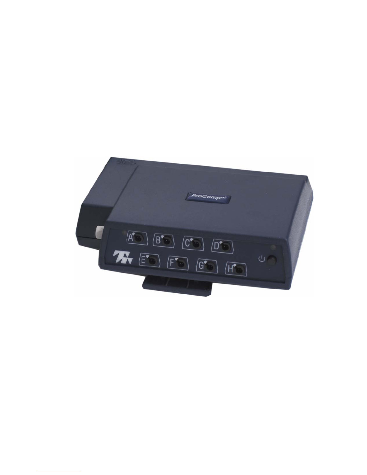
The ProComp Infiniti™ encoder is an eight (8) channel, multi-modality device for real-time
computerized biofeedback and data acquisition. It has 8 protected pin sensor inputs with two
channels sampled at 2048 s/s and six channels sampled at 256 s/s. The ProComp Infiniti encoder
is able to render a wide and comprehensive range of objective physiological signs used in clinical
observation and biofeedback.
The ProComp Infiniti basic package includes the following hardware:
One eight-channel ProComp Infiniti encoder unit
One TT-USB interface unit
A supply of fiber optic cable (1’ and 10’ cables)
Four alkaline ‘AA’ batteries
Thought Technology’s advanced design and active electronic sensors meet exacting standards for
instrument accuracy, sensitivity, durability, and ease of use. All sensors are completely noninvasive and require little or no preparation for use. Depending on the software being used with
the ProComp Infiniti encoder, these may include sensors specialized for:
Electromyography (EMG) Electrocardiography (EKG)
Electroencephalography (EEG) Skin Conductance
Skin Temperature Voltage Isolation
Respiration waveform, rate, and amplitude
Blood Volume Pulse waveform, heart rate, and
amplitude (BVP)
Goniometer
Force
Torsiometer
The sensors pass signals to the host computer via the microprocessor-controlled ProComp Infiniti
encoder unit. The encoder samples the incoming signals, digitizes, encodes, and transmits the
sampled data to the TT-USB interface unit. A fiber optic cable is used for transmission, providing
maximum freedom of movement, signal fidelity, and electrical isolation. Cable lengths up to 25
feet can be used without signal degradation. A unique feature of the system design allows inputs
to accept any sensor, interchangeably (except the raw EMG MyoScan sensors which are used on
channel A and B). This allows a wide variety of configurations to be created by simply changing
the sensor types.
The TT-USB interface unit is connected to one of the host computer’s USB ports. It receives the
data arriving from the encoder in optical form and converts it into the USB format to
communicate with the software.
Please note, some hardware features may not be supported by all software programs. Consult the
software manual for a full list of features supported.
ProComp Infiniti Hardware Manual
8

Please note, some software programs will not function with a TT-USB, but require use of a PRO-SB in
its place.
Connecting the Encoder,
TT-USB and Sensors
SETTING UP THE ENCODER UNIT
Cut a convenient length of fiber optic cable cleanly and evenly using a sharp blade, or use the
whole length rolled up out of the way.
IMPORTANT: Winding the fiber optic cable in a loop smaller than 4 inches (10 cm) or bending it sharply
will damage the cable!
1. Plug the USB cable connected to the TT-USB interface unit supplied with the USB
connector on the computer being used. (If using the BioGraph
the Pro-SB in place of the TT-USB as described in the BioGraph
2. Insert one end of the fiber optic cable into the optical receiver jack on the rear face of
the TT-USB Interface unit and the other into the optical transmitter jack on the front of
the ProComp Infiniti encoder. Before inserting the cable, it may be necessary to loosen
the jack heads by turning them counter-clockwise.
3. Ensure that both ends of the optical cable are
1.9 cm) into the jacks and that the heads are screwed down firmly.
4. Wind excess fiber optic cable into a large loop (approx. 6 inches, 15 cm).
5. Plug the sensors you wish to use into the input jacks on the front of the encoder unit.
6. Load four 1.5 V Alkaline or rechargeable Nickel-Metal Hydride (NiMH) batteries into the
encoder unit’s battery pack; check battery orientation being sure to respect the polarities
indicated on the inside of the battery compartment.
7. Push the encoder unit’s power button for 1 second.
8. Check that the encoder’s blue ‘ON’ indicator directly above the ON button is lit; if it is
not, check the condition and orientation of your batteries.
9. To switch the encoder ‘OFF’ push the power button for 1 second and ensure that the
blue indicator is no longer lit.
You may leave the encoder unit power ON if you intend to continue on to the following sections.
inserted all the way (about ¾ of an inch,
®
2.1 software please use
®
2.1 software manual.)
ProComp Infiniti Hardware Manual
9
TT-USB Installation Notes:
The TT-USB unit is a Plug and Play device (PnP) i.e., oversimplified, Plug-and-Play automatically
tells the software (device drivers) where to find various pieces of hardware (devices). The driver
for the TT-USB is installed along with the BioGraph Infiniti Main Application software. Therefore,
before you could use the TT-USB with your ProComp Infiniti encoder the Biograph Infiniti
Software must be installed on your computer.
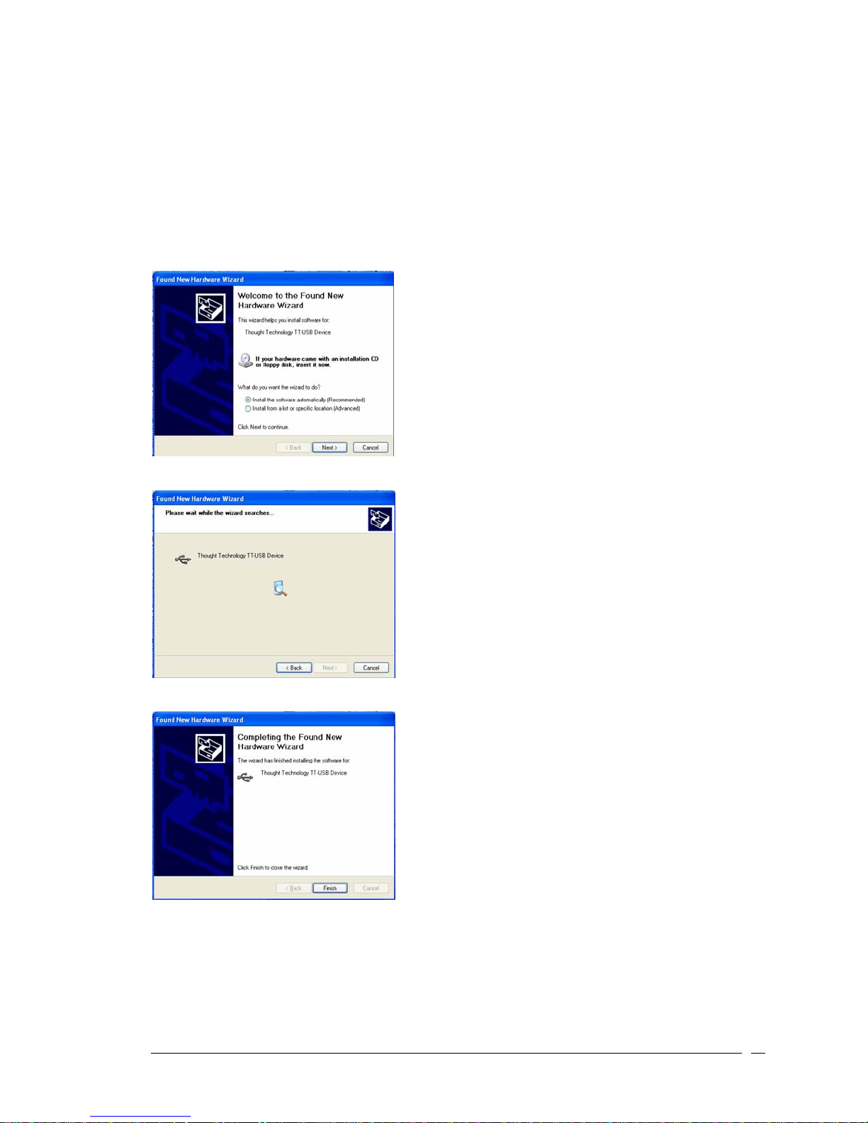
In Windows XP screens similar to the one below may appear
.
Windows should recognize when new
device is plugged into one of its USB
ports
Let windows install the software
automatically
If the BioGraph Infiniti Software was
already installed on you computer
Windows® will automatically install
the proper drivers.
Unsigned Driver Messages
Microsoft uses digital signatures for device drivers to let users know that drivers are compatible
with Microsoft® Windows® XP, Windows 2000. A driver’s digital signature indicates that the
driver was tested with Windows for compatibility and has not been altered since testing.
ProComp Infiniti Hardware Manual
10
If a driver is “unsigned” (indicating that certification of the driver by Microsoft was pending but
not yet complete at the time of release), you might see one of the following warnings during
driver installation or update.
• Digital Signature Not Found warning. Click the Yes button to complete the driver
installation.
• On Windows XP systems, a Hardware Installation or Software Installation warning that
the software has not passed Windows logo testing to verify its compatibility with
windows XP. Click the Continue Anyway button to complete the driver installation.
Windows 2000 and XP have a new feature that controls the installation of unsigned device
drivers. There are three settings for Driver Signing:
• Block: This will prevent the installation of unsigned drivers.
• Warn: This will prompt the user whether to install an unsigned device driver or not.
• Ignore: The system will install unsigned drivers without prompting the user.
The TT-USB device drivers are unsigned and you may need to set your system to Warn or
Ignore. The rest of this section describes how to do that.
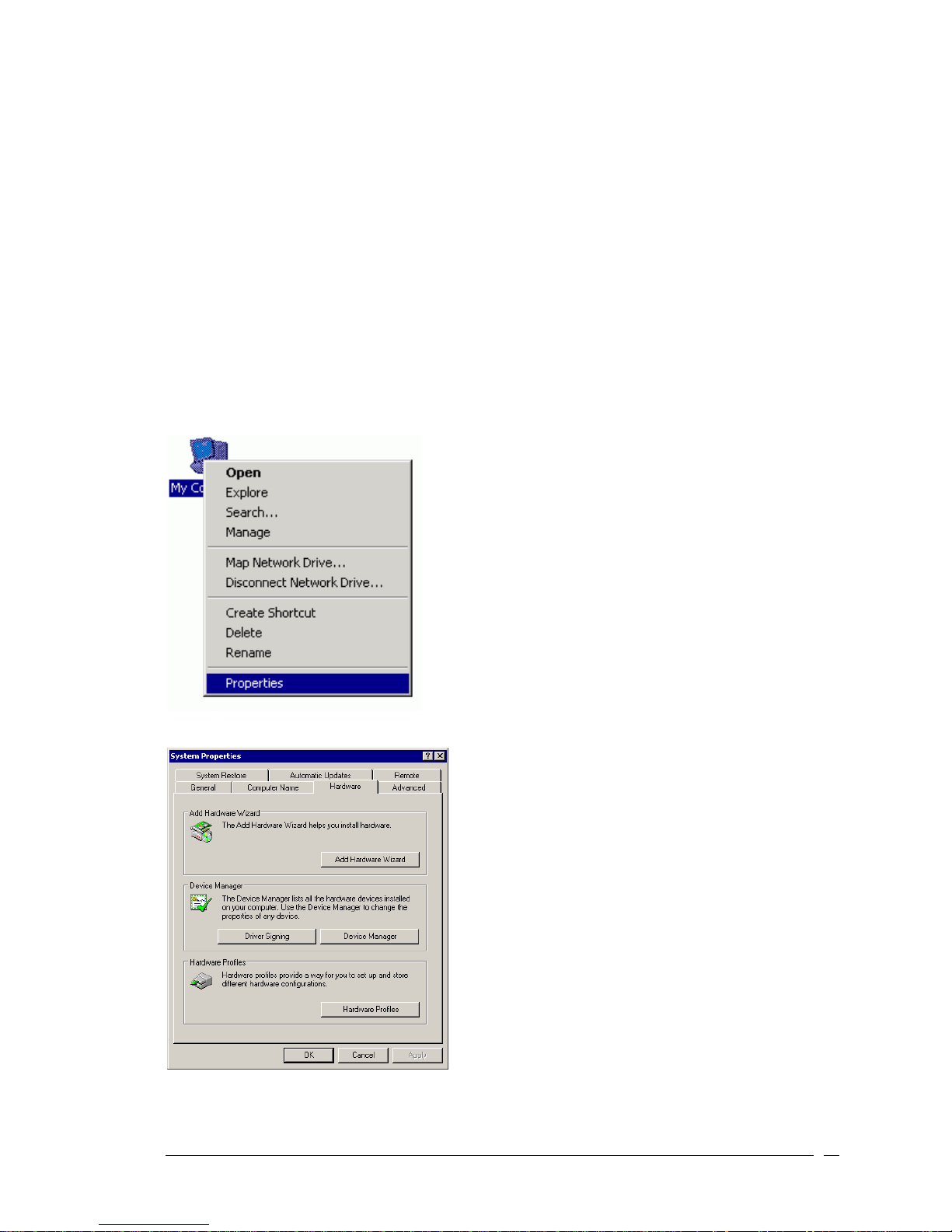
First, locate the My Computer icon on
the desktop or in Windows Explorer.
Right-click on the My Computer icon
and select Properties.
Windows XP
After clicking on the Hardware tab
your screen should look like one of the
two screens shown. Now click on
Driver Signing.
ProComp Infiniti Hardware Manual
11
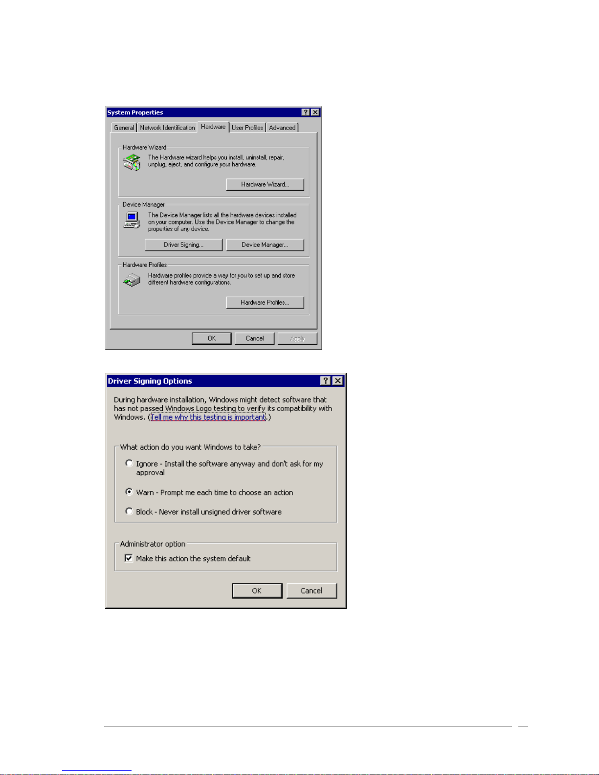
Windows 2000
Make sure that either Warn or Ignore
is selected. Then click on OK.
ProComp Infiniti Hardware Manual
12
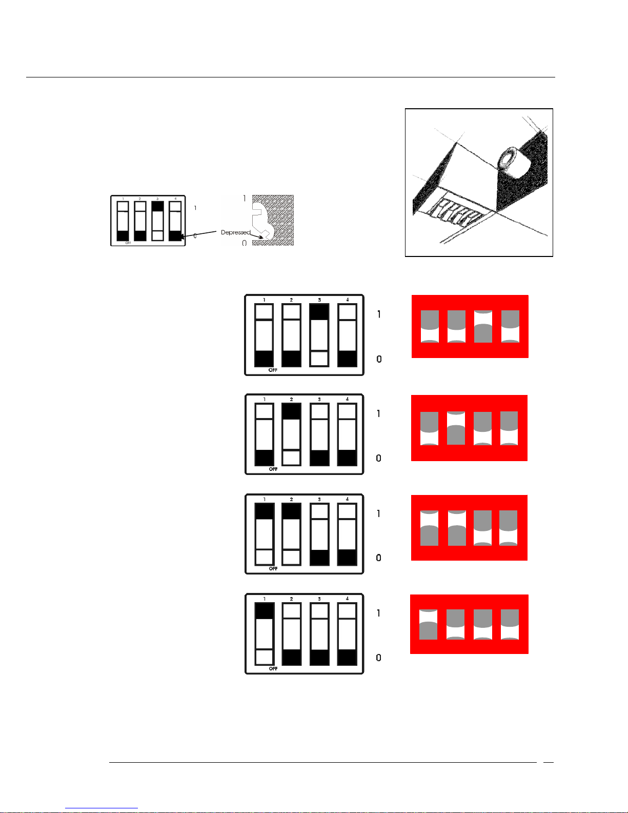
ENCODER DIP SWITCH SETUP
ProComp Infiniti encoder units have switches located on the
it to the left of the belt clip. The switches can be flipped up and
0 (zero) position with the aid of a paper clip or small pointed
ront of the encoder facing up, verify that the switches are set
oftware in use. Below is an example of the switch with the
n indicated. The Black section represents the depressed state.
For use with the ProComp BioGraph
Infiniti software and the TT-USB
interface:
Channels A & B 2048
samples/second
Channels C to J 256
samples/second
For use with the BioGraph,
CardioPro or MultiTrace software
and the Pro-SB interface:
Channels A & B 256
samples/second,
Channels C to H 32
samples/second.
For use with the BioResearch
software and the Pro-SB interface:
Channels A & B 200
samples/second,
Channels C to H 20
samples/second.
ON
1 43
2
1
0
ON
1 43
2
1
0
ON
143
2
1
0
For use with the Neurocybernetics
(EEG Spectrum), NeuroCare Pro
software and the Pro-SB interface:
Channels A & B 256
samples/second,
Channels C to H 32
samples/second.
All other switch settings are reserved for later use.
ProComp Infiniti Hardware Manual
ON
1 43
2
1
0
Red Slide Switch
13
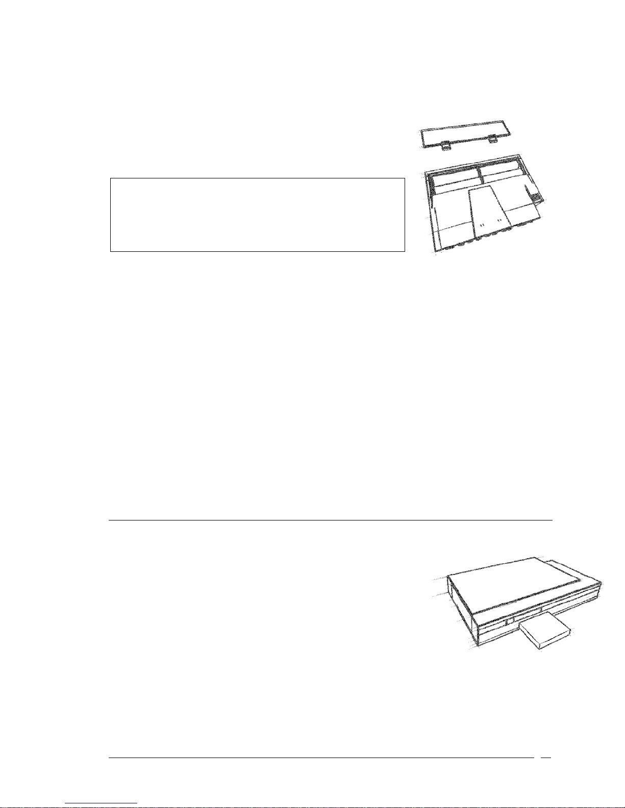
Battery Placement
Opening The Compartment
Looking at the underside of the ProComp Infiniti device, you will
see a long door in the plastic enclosure. Holding the encoder
with the connectors facing you and with the door up, push lightly
down and back with your thumbs on the door to slide it open.
Attention:
The internal workings of the ProComp Infiniti encoder is not intended
to be opened for repair except by qualified service personnel. The
tamper-evident seal under the batteries in the battery compartment
should not be removed or broken. Thought Technology may refuse to
honor the unit’s warranty if the seal is broken.
Polarity
When the compartment cover has been slid out, place four AA batteries in the slots, observing
the polarity as illustrated. Please note that a diagram of the correct battery polarity is embossed
on the inside surface of the compartment.
Closing The Compartment
Slide the door back into the ProComp Infiniti case, gently pushing it in until you feel the click of
the locking mechanism.
Keeping An Eye On The Battery Level
Since each sensor draws a small amount of power from the batteries when connected to the
ProComp Infiniti, it is better to connect only the sensors that are going to be used for a session
before you start recording; this will ensure maximal battery life. Most Thought Technology
software applications will display a battery power indicator; we recommend that you replace the
batteries as soon as this indicator falls below about 50% of the battery power.
COMPACT FLASH
The compact flash (CF) is used as an alternative storage medium for
data being recorded by the encoder. The CF card is a small square
approximately the size of a box of matches and is inserted into the
rear surface of the encoder with its label facing up. The encoder is
delivered with a protective insert in the compact flash slot. To
remove it, push the button next to the slot once to eject the button,
then push again to remove the card, pushing the button back in.
The CF card can then be inserted; you will notice that the CF card
can only be inserted one way into the encoder to protect from
incorrect insertion. When inserted properly it will be flush with the
encoder rear. Follow the procedure above to remove this card when
no longer required, and re-insert the protective insert. CF cards
require a CF card reader to transfer data to the PC. The CF cards
and reader can be purchased from most computer stores. Before its
ProComp Infiniti Hardware Manual
14
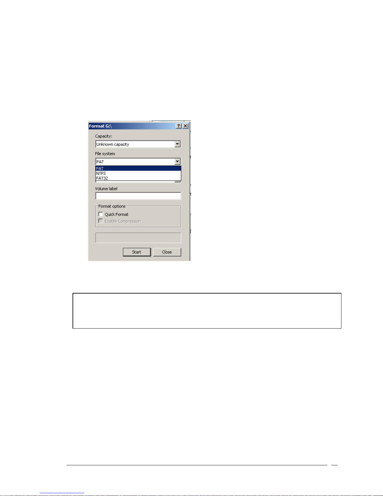
first use in the encoder, a CF card requires PC formatting using the
file manager. With the CF card inserted into the reader connected
to the PC, from Windows open the file manager and identify the
Removable Drive. Right click the removable drive and select
Format.
Select Format Type Full, if using Windows® XP select file system FAT not FAT32 and select
Start. When this is complete use the single master file build function provided by the Infiniti
Software to finish the process.
It is recommended that you temporarily disable any virus scanning utility while formatting the
Compact Flash as this will considerably increase the speed of the process.
Attention:
Formatting CF Card with File System other than FAT will render it Inoperable.
Users should follow the appropriate procedures used for disconnecting peripheral devices when
unplugging the Compact Card from its PC reader.
Compact Flash Setup
Compact Flash Rebuilding
To rebuild the Compact Flash for use in the encoder, follow these steps:
1. Place the CF card in the CF Card Reader connected to the PC.
2. From the Infiniti software's main screen, select "Compact Flash Options", and then
"Rebuild Compact Flash".
3. Select the "Create" option and press OK. Wait for the operation to complete. This may
take some time, especially for larger Compact Flash cards.
4. After the operation has concluded, you may remove the CF card from the reader. It is
now ready for use in the encoder. However, you may wish to first initialize the Compact
Flash card so that the encoder's date and time will be set (see below).
ProComp Infiniti Hardware Manual
15
 Loading...