

Thorsis Technologies isNet H@rt 4, isNet H@rt8+AI, isNet Lite, isNet H@rt 8, isNet DIO4 User Manual
...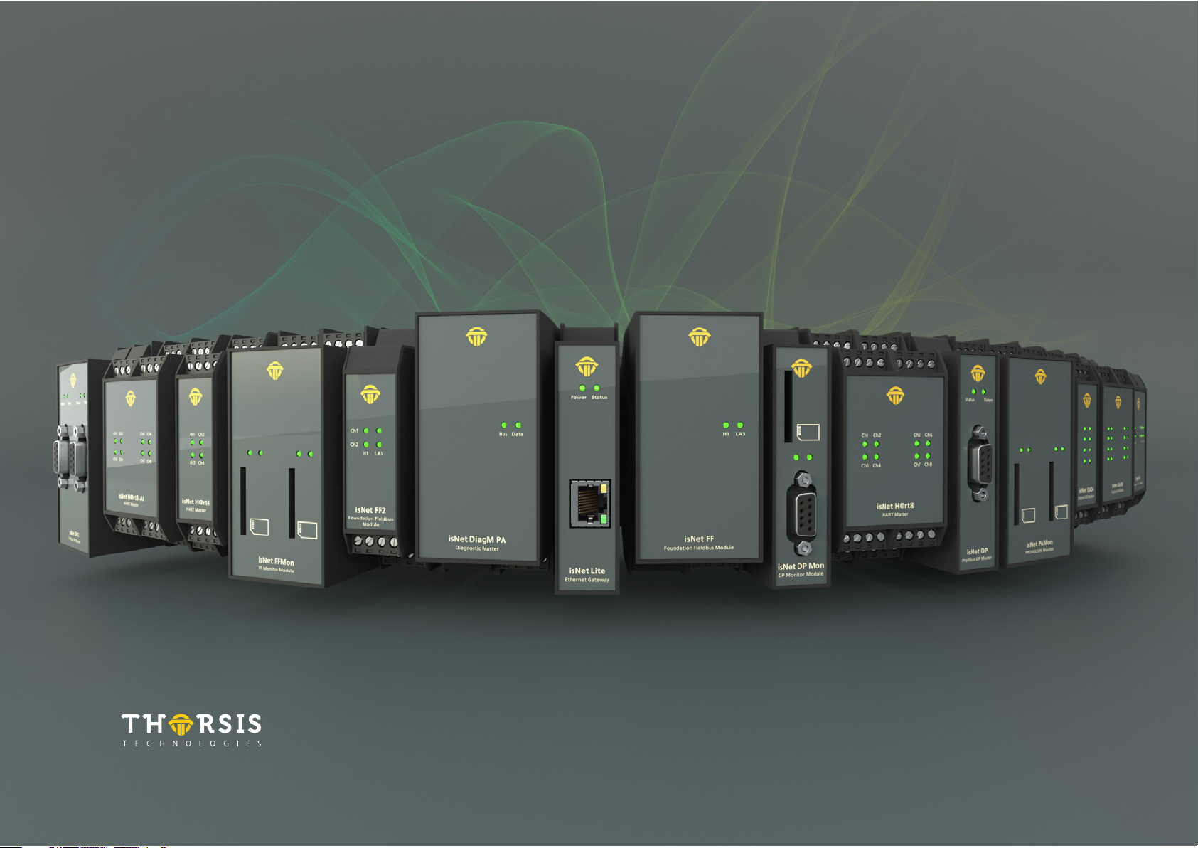
isNet Line
Modular Gateway Solution
USER MANUAL

Table of content
1. isNet Line . . . . . . . . . . . . . . . . . . . . . . . . . . . . . . . . . . . . . . . . . . . . . . . . . . . . . . . . . . . . . . . . . . . . . . . . . . . . . . . . . . . . . . . . . . . . . . . . . . . . . . . . . 5
1.1 Dimensional drawing . . . . . . . . . . . . . . . . . . . . . . . . . . . . . . . . . . . . . . . . . . . . . . . . . . . . . . . . . . . . . . . . . . . . . . . . . . . . . . . . . . . . . . . . . . . . . . . 7
1.2 isNet Lite . . . . . . . . . . . . . . . . . . . . . . . . . . . . . . . . . . . . . . . . . . . . . . . . . . . . . . . . . . . . . . . . . . . . . . . . . . . . . . . . . . . . . . . . . . . . . . . . . . . . . . . . . 8
1.3 isNet DP . . . . . . . . . . . . . . . . . . . . . . . . . . . . . . . . . . . . . . . . . . . . . . . . . . . . . . . . . . . . . . . . . . . . . . . . . . . . . . . . . . . . . . . . . . . . . . . . . . . . . . . . . 12
1.4 isNet DiagM PA . . . . . . . . . . . . . . . . . . . . . . . . . . . . . . . . . . . . . . . . . . . . . . . . . . . . . . . . . . . . . . . . . . . . . . . . . . . . . . . . . . . . . . . . . . . . . . . . . . . 15
1.5 isNet H@rt . . . . . . . . . . . . . . . . . . . . . . . . . . . . . . . . . . . . . . . . . . . . . . . . . . . . . . . . . . . . . . . . . . . . . . . . . . . . . . . . . . . . . . . . . . . . . . . . . . . . . . . 19
1.6 isNet H@rt+AI . . . . . . . . . . . . . . . . . . . . . . . . . . . . . . . . . . . . . . . . . . . . . . . . . . . . . . . . . . . . . . . . . . . . . . . . . . . . . . . . . . . . . . . . . . . . . . . . . . . . 23
1.7 isNet DIO . . . . . . . . . . . . . . . . . . . . . . . . . . . . . . . . . . . . . . . . . . . . . . . . . . . . . . . . . . . . . . . . . . . . . . . . . . . . . . . . . . . . . . . . . . . . . . . . . . . . . . . . 26
1.8 isNet PAMon and DPMon . . . . . . . . . . . . . . . . . . . . . . . . . . . . . . . . . . . . . . . . . . . . . . . . . . . . . . . . . . . . . . . . . . . . . . . . . . . . . . . . . . . . . . . . . . . 29
1.9 isNet FFMon . . . . . . . . . . . . . . . . . . . . . . . . . . . . . . . . . . . . . . . . . . . . . . . . . . . . . . . . . . . . . . . . . . . . . . . . . . . . . . . . . . . . . . . . . . . . . . . . . . . . . . 32
2. Hardware installation . . . . . . . . . . . . . . . . . . . . . . . . . . . . . . . . . . . . . . . . . . . . . . . . . . . . . . . . . . . . . . . . . . . . . . . . . . . . . . . . . . . . . . . . . . . . . . 35
2.1 Safety instructions . . . . . . . . . . . . . . . . . . . . . . . . . . . . . . . . . . . . . . . . . . . . . . . . . . . . . . . . . . . . . . . . . . . . . . . . . . . . . . . . . . . . . . . . . . . . . . . . 35
2.2 Mechanical installation . . . . . . . . . . . . . . . . . . . . . . . . . . . . . . . . . . . . . . . . . . . . . . . . . . . . . . . . . . . . . . . . . . . . . . . . . . . . . . . . . . . . . . . . . . . . . 36
2.3 Electrical installation . . . . . . . . . . . . . . . . . . . . . . . . . . . . . . . . . . . . . . . . . . . . . . . . . . . . . . . . . . . . . . . . . . . . . . . . . . . . . . . . . . . . . . . . . . . . . . . 38
3. Web Interface . . . . . . . . . . . . . . . . . . . . . . . . . . . . . . . . . . . . . . . . . . . . . . . . . . . . . . . . . . . . . . . . . . . . . . . . . . . . . . . . . . . . . . . . . . . . . . . . . . . . 39
3.1 Configuration of the IP address . . . . . . . . . . . . . . . . . . . . . . . . . . . . . . . . . . . . . . . . . . . . . . . . . . . . . . . . . . . . . . . . . . . . . . . . . . . . . . . . . . . . . . 40
3.2 Update of the Firmware . . . . . . . . . . . . . . . . . . . . . . . . . . . . . . . . . . . . . . . . . . . . . . . . . . . . . . . . . . . . . . . . . . . . . . . . . . . . . . . . . . . . . . . . . . . . 41
3.3 Soft-Restart . . . . . . . . . . . . . . . . . . . . . . . . . . . . . . . . . . . . . . . . . . . . . . . . . . . . . . . . . . . . . . . . . . . . . . . . . . . . . . . . . . . . . . . . . . . . . . . . . . . . . . 41
3.4 Password Protection . . . . . . . . . . . . . . . . . . . . . . . . . . . . . . . . . . . . . . . . . . . . . . . . . . . . . . . . . . . . . . . . . . . . . . . . . . . . . . . . . . . . . . . . . . . . . . . 42
3.5 Activating MODBUS functionality . . . . . . . . . . . . . . . . . . . . . . . . . . . . . . . . . . . . . . . . . . . . . . . . . . . . . . . . . . . . . . . . . . . . . . . . . . . . . . . . . . . . 43
3.6 MODBUS status . . . . . . . . . . . . . . . . . . . . . . . . . . . . . . . . . . . . . . . . . . . . . . . . . . . . . . . . . . . . . . . . . . . . . . . . . . . . . . . . . . . . . . . . . . . . . . . . . . . 44
3.7 HART over IP . . . . . . . . . . . . . . . . . . . . . . . . . . . . . . . . . . . . . . . . . . . . . . . . . . . . . . . . . . . . . . . . . . . . . . . . . . . . . . . . . . . . . . . . . . . . . . . . . . . . . 45
2

4. FDT Configuration . . . . . . . . . . . . . . . . . . . . . . . . . . . . . . . . . . . . . . . . . . . . . . . . . . . . . . . . . . . . . . . . . . . . . . . . . . . . . . . . . . . . . . . . . . . . . . . . . 46
5. isNet Lite – PROFINET . . . . . . . . . . . . . . . . . . . . . . . . . . . . . . . . . . . . . . . . . . . . . . . . . . . . . . . . . . . . . . . . . . . . . . . . . . . . . . . . . . . . . . . . . . . . . . 50
5.1 Workflow of the engineering process . . . . . . . . . . . . . . . . . . . . . . . . . . . . . . . . . . . . . . . . . . . . . . . . . . . . . . . . . . . . . . . . . . . . . . . . . . . . . . . . . 51
5.2 Creation of the GSDML file . . . . . . . . . . . . . . . . . . . . . . . . . . . . . . . . . . . . . . . . . . . . . . . . . . . . . . . . . . . . . . . . . . . . . . . . . . . . . . . . . . . . . . . . . 52
5.3 Integration in SIMATIC Manager . . . . . . . . . . . . . . . . . . . . . . . . . . . . . . . . . . . . . . . . . . . . . . . . . . . . . . . . . . . . . . . . . . . . . . . . . . . . . . . . . . . . . 57
6. isNet Lite – Modbus . . . . . . . . . . . . . . . . . . . . . . . . . . . . . . . . . . . . . . . . . . . . . . . . . . . . . . . . . . . . . . . . . . . . . . . . . . . . . . . . . . . . . . . . . . . . . . . 66
7. isFieldDiagnosis . . . . . . . . . . . . . . . . . . . . . . . . . . . . . . . . . . . . . . . . . . . . . . . . . . . . . . . . . . . . . . . . . . . . . . . . . . . . . . . . . . . . . . . . . . . . . . . . . . . 67
8. Document History . . . . . . . . . . . . . . . . . . . . . . . . . . . . . . . . . . . . . . . . . . . . . . . . . . . . . . . . . . . . . . . . . . . . . . . . . . . . . . . . . . . . . . . . . . . . . . . . .68
3

CERTIFICATE OF CONFORMITY
According to EC Directive 2014/30/EU (electromagnetic compatibil-
ity) of February 26th 2014 and according to EC Directive 2011/65/
EU (RoHS II) of June 8th 2011. We hereby declare, that the devices
indicated below in its design and construction, are in conformity
CHANGES OR MODIFICATIONS NOT APPROVED BY THORSIS TECHNOLOGIES VOID THE VALIDITY OF THE DECLARATION.
Produkt name Order code
isNet Lite 19300-0101
isNet DP 19300-0401
isNet DP2 19300-0501
isNet DiagM PA 19300-1201
isNet H@rt 4 19300-0601
isNet H@rt 8 19300-0701
isNet H@rt8+AI 19300-0702
isNet DIO4 19300-1301
isNet DIO8 19300-1401
isNet DPMon 19300-0201
isNet PAMon 19300-0301
isNet FFMon 19300-0801
with the essential safety and health requirements of the EC Directive
2014/30/EU. The devices do not contain material as declared in the EC
Directive 2011/65/EU (RoHS II).
Manufacturer
Thorsis Technologies GmbH
Oststr. 18
39114 Magdeburg
Germany
STANDARDS USED: EN 61326-1:2013
Magdeburg, 2018-08-28
Dipl.-Ing. Thorsten Szczepanski,
Managing director
4
1. isNet Line
The product family isNet Line is a modular gateway solution to inte-
grate legacy fieldbuses like HART, Profibus or FOUNDATION Fieldbus
into Ethernet based fieldbus environments. It can be used as a gateway
to connect e.g. HART Transmitters or Profibus slave devices to an Ether-
net cable. Typical applications are for example device parameterization,
asset management, fieldbus diagnosis, Profinet to Profibus gateways,
Modbus/TCP to HART gateways or any other conceivable combination
between Ethernet protocols and HART or Profibus protocols.
The system is modular and consists of an Ethernet head module
and different fieldbus expansion modules. Expansion modules are
available for HART, Profibus DP, Profibus PA as well as FOUNDATION
Fieldbus. Up to 5 expansion modules can be mounted to a head
module. Depending on the application a free combination of any of
these expansion modules is possible.
5
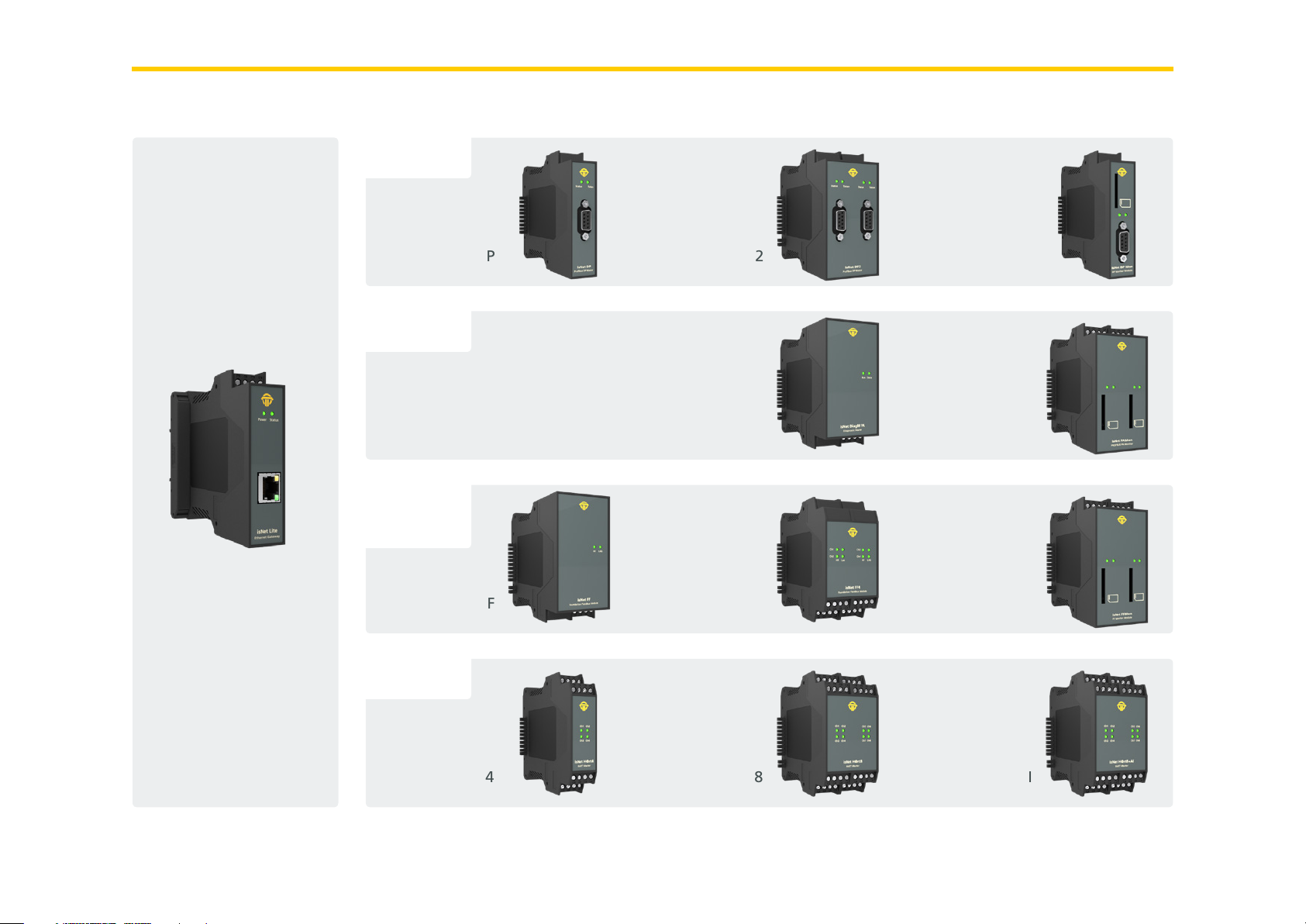
overview
PROFIBUS DP
isNet Lite
isNet DP
PROFIBUS PA
Foundation
Fieldbus
isNet FF
HART
isNet DP2
isNet DiagM PA
isNet FF4
isNet DPMon
isNet PAMon
isNet FFMon
isNet H@rt4
isNet H@rt8
isNet H@rt+AI
6
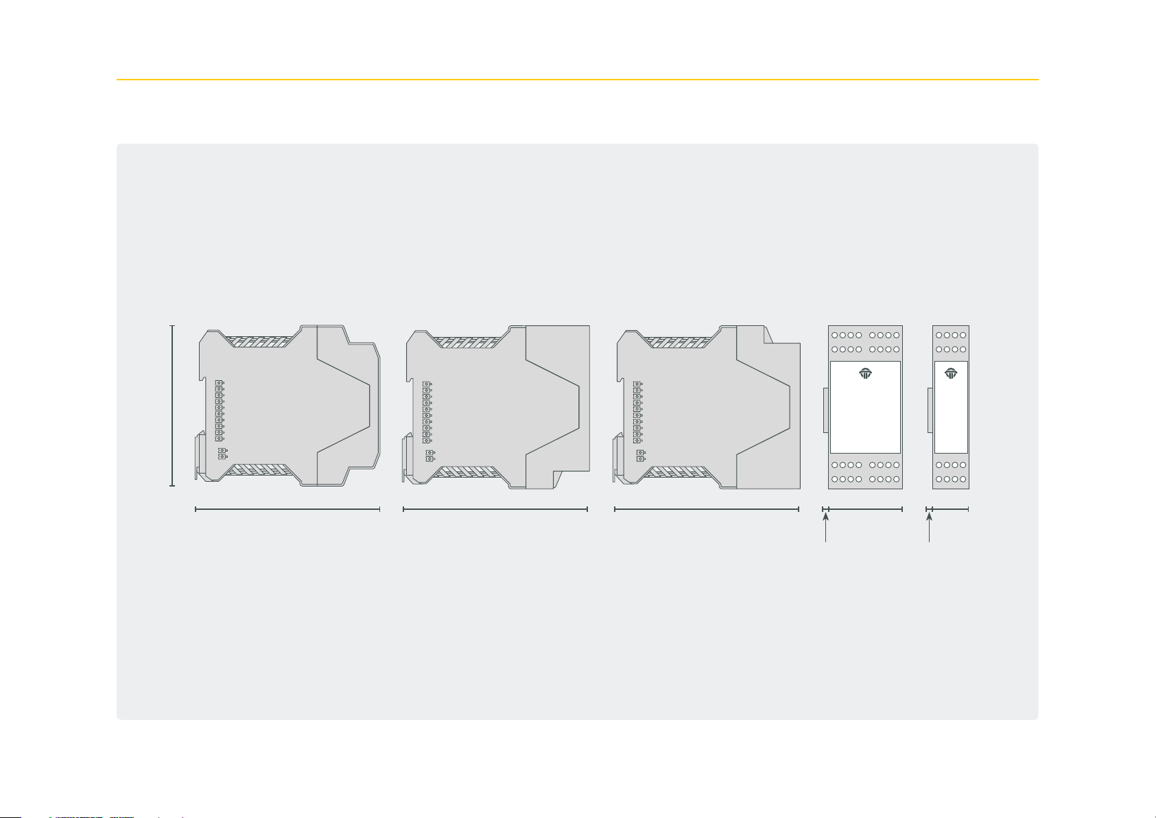
1.1 Dimensional drawing
99 mm
114 ,5 m m
114 ,5 m m 114 ,5 m m 45,2 mm
6,7 mm 6,7 mm
22,5 mm
7
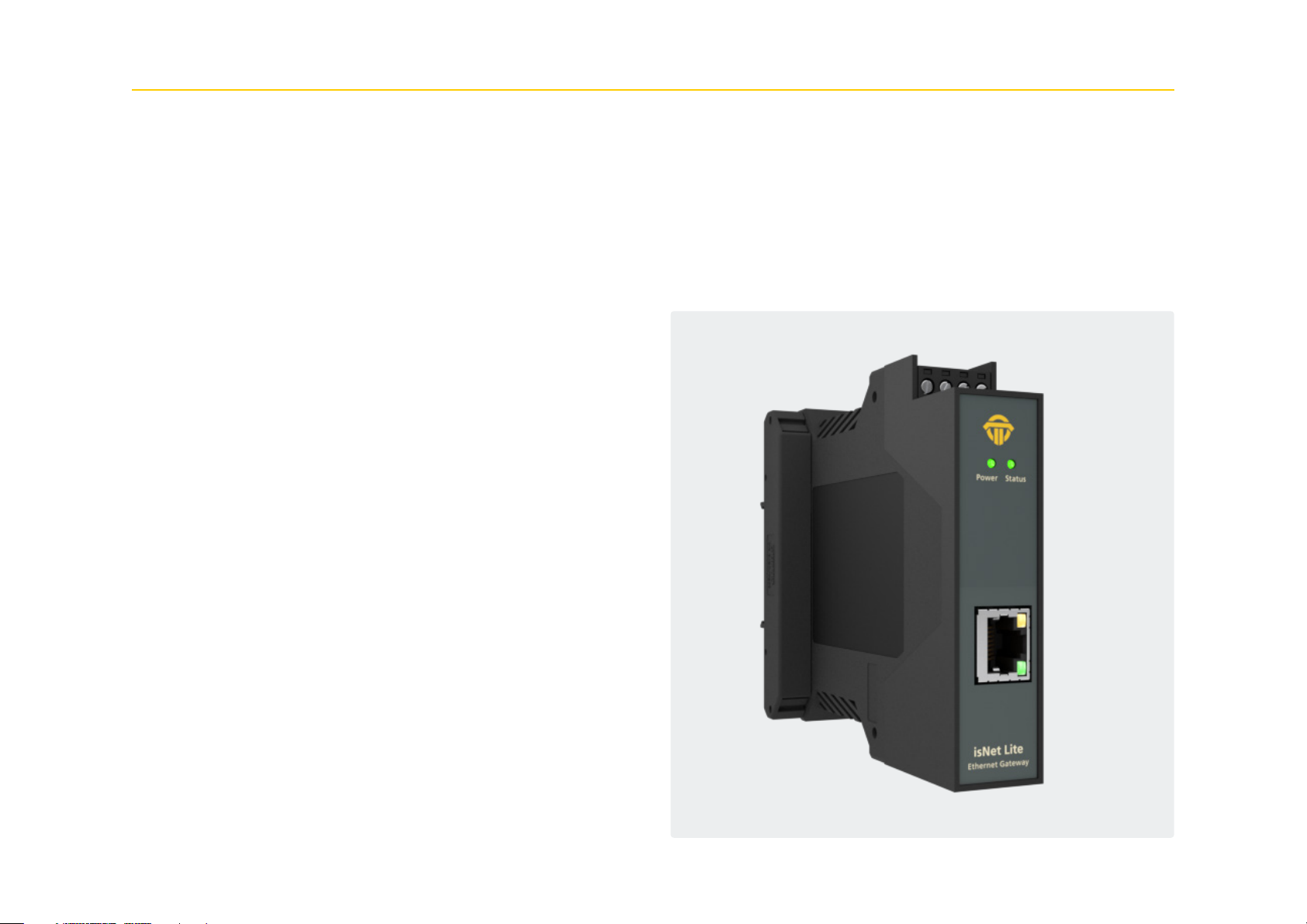
1.2 isNet Lite
The Ethernet module isNet Lite is the head module of every isNet
Line gateway solution. In combination with any of the fieldbus
expansion modules its purpose is to exchange process data between
field devices and Ethernet based PLCs. Additionally it allows engi-
neering stations to access field device parameters for configuration
purposes, diagnosis and asset management.
The isNet Lite is equipped with a RJ45 socket for an Ethernet cable,
a side connector for the fieldbus expansion modules and a 24V DC
connector for power supply. Incoming power is also forwarded to
the side connector to supply all connected fieldbus expansion mod-
ules.
The firmware of the isNet Lite implements Ethernet based fieldbus
protocols for a direct communication link to a PLC. The gateway can
be used as a Profinet device or as a Modbus-TCP server. For access to
HART field devices the HART over IP protocol is implemented too.
To provide parameter access from a PC based solution, a Communi-
cation DTM is available, which allows to integrate the isNet gateway
into any FDT based application such as PACTware, Fieldcare or Asset
Vision Basic. Also an OPC server is available for data access from any
OPC client application. For further customization of the device, a
driver interface allows integration into customer specific applica-
tions.
The isNet Lite can be controlled and configured by using a web in-
terface which allows diagnosis and maintenance of the main module
and its connected expansion modules (see chapter 3 “Web Interface”
on page 39)
8
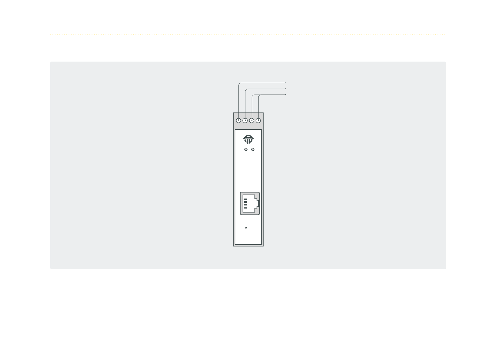
1. 2.1 Channel assignment
24V
GND
Shield
PowerStatus
isNet Lite
Ethernet Gateway
9
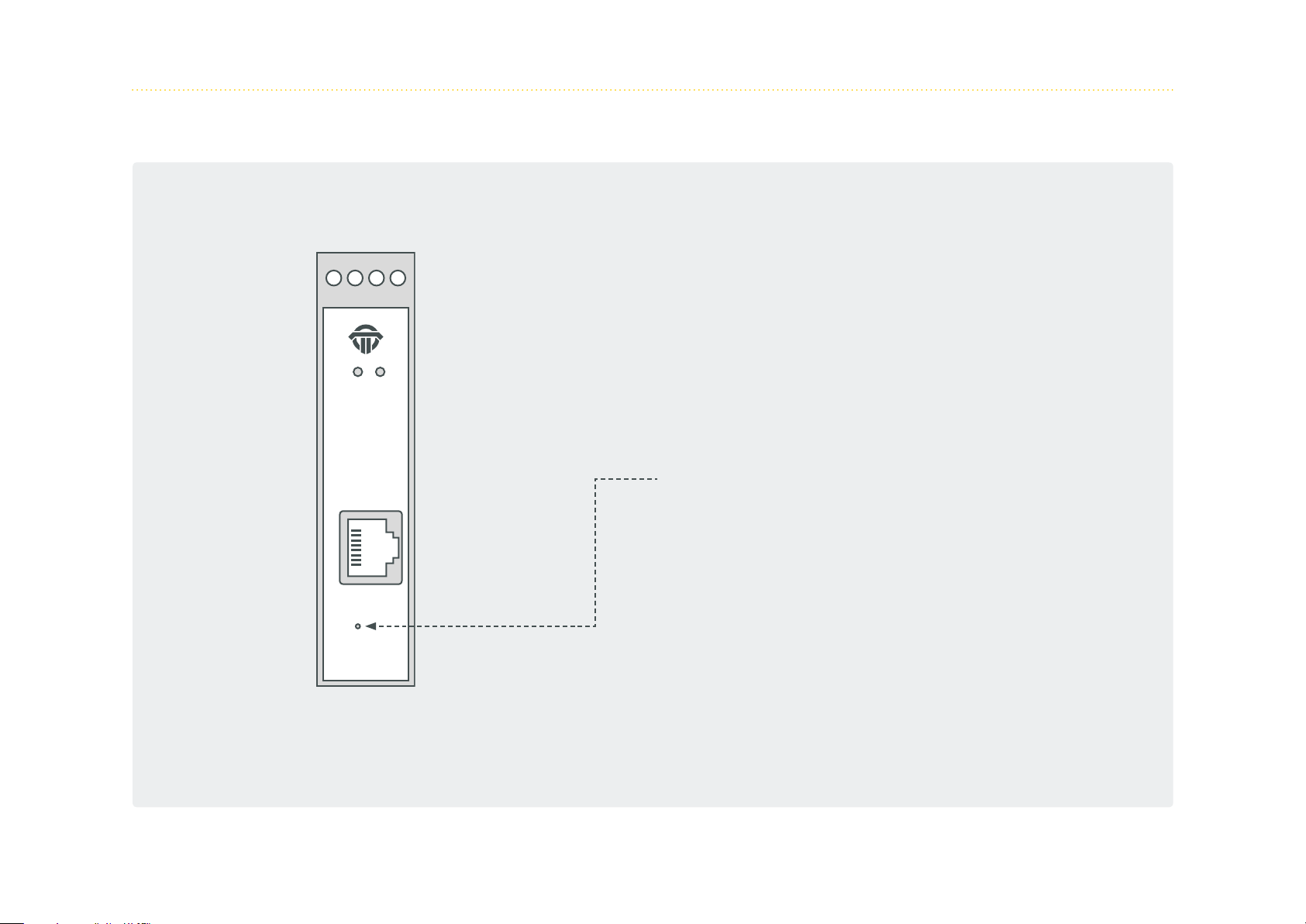
1.2.2 Hardware Reset isNet Lite
PowerStatus
There may be reasons to restore firmware defaults of the isNet
Lite like a failed firmware upgrade, a forgotten IP address or an
IP address set to DHCP without having a DHCP server available in
the network. In all these cases the user can reset the hardware
back to firmware defaults by using the reset button. This button
is located behind a small hole next to the RJ45 connector. In order
to perform the firmware reset, the user needs to:
• switch off power from the hardware
• press the button (e.g. with a paper clip) and hold
• apply power again while still holding the reset button and
• wait for at least 5 more seconds before releasing the reset
button
isNet Lite
Ethernet Gateway
After releasing the reset button, the firmware will take some time
to reinitialize to default settings, do not disconnect from power.
As a result of a firmware reset, the module will have its default IP
address 192.168.0.10 and all firmware updates are undone.
10

1.2.3 Technical Details
Electrical data
Interface RJ 45 (Ethernet)
Controller ARM9 32Bit 400 MHz
RAM 32 MB
Flash 256 MB
Transmission rate Ethernet/PROFINET/MODBUS
10 Mbit/s – 100 Mbit/s
Power supply 19,2 - 30V DC, max 4A
Power consumption 1,1W (typ.) ... 1,5W (max)
Max. buffer time RTC 2h
Mechanical data
LxWxH in mm 114,5 x 22,5
(1)
x 99
Weight 140g
0,5 mm2 .. 2,5 mm2/
Wire size
AWG20..AWG 12
(1) Dimensions without lateral plugs
(4) Cable entries and field wiring must be suitable for an operating temperature of at
least +20°C above ambient.
(4)
Environmental data
Temperature range - 40 °C <= T
- 40 °F <= T
Storage temperature - 40 °C <= T
- 40 °F <= T
<= 70 °C
amb
<= 158 °F
amb
<= 85 °C
amb
<= 185 °F
amb
Pollution degree 2
Altitude up to 2000 m
Content
Driver software Windows XP, Vista, 7, 8 or 10
Hardware, User manual
Delivery content
isNet Line on CD
Oder code 19300-0101
The default address of the module is: 192.168.0.10 subnet mask 255.255.255.0
11
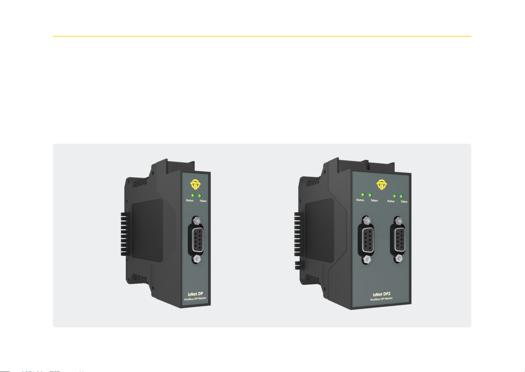
1.3 isNet DP
With the isNet DP module the main module isNet Lite can be extend-
ed to work as a PROFIBUS-DP Ethernet Gateway. The main module
can be enhanced with a maximum of 5 PROFIBUS modules. The isNet
DP modules are available as one and two channel version, so up to
ten PROFIBUS channels can be connected to a head station. The pro-
tocols DP and DP/V1 are supported. Access to the PROFIBUS network
is provided by a SubD9 connector (female). The modules offer all
recognized baud rates of up to 12 Mbit/s.
The modules are operated via the isNet DP DTM from Thorsis Tech-
nologies. The DTM is compliant to the FDT 1.2.1 specification and
integrates the gateway into every FDT-frame application.
12

1. 3.1 Technical details
1-Channel isNet DP 2-Channel isNet DP2
Connectors 1 RS-485 2 RS-485
Power consumption 2,4W 2,5W
LxWxH in mm 114,5 x 22,5
(1)
x 99 114,5 x 45
(1)
x 99
Weight 140 g 250 g
Temperature range 0 °C <= T
<= 50°C / 32 °F <= T
amb
<= 122°F
amb
Transmission rate 9,6 kbit/s – 12,0 Mbit/s
Driver software Windows XP, Vista, 7,8 or 10
Delivery content Hardware, isNet DTM Library, Pactware, User manual isNet Line on CD
Order code 19300-0401 19300-0501
(1) Dimensions without lateral plugs
13
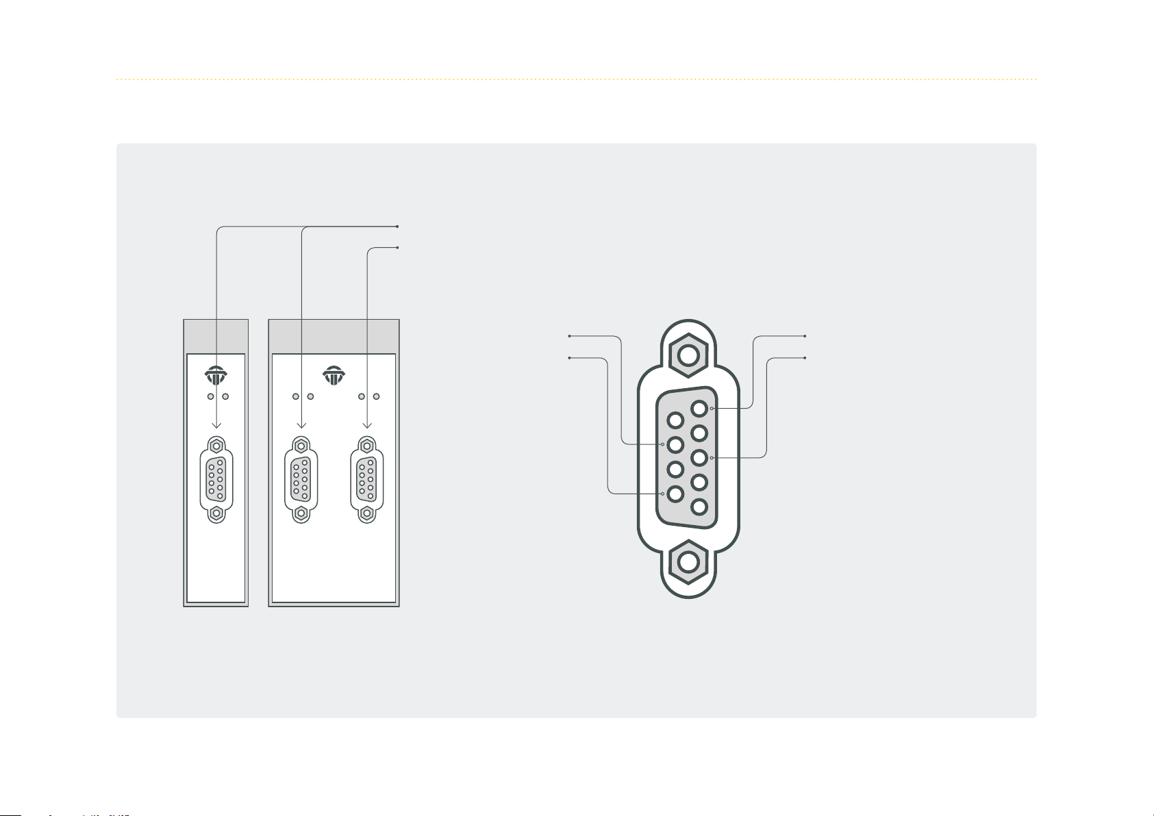
1.3.2 Channel assignment
nT
Channel 1
Channel 2
Status Token
isNet DP
Profi bus DP Master
Status StatusToke
Profi bus DP Master
isNet DP2
oken
+5V
A
Ground
B
5
9
4
8
3
7
2
6
1
14
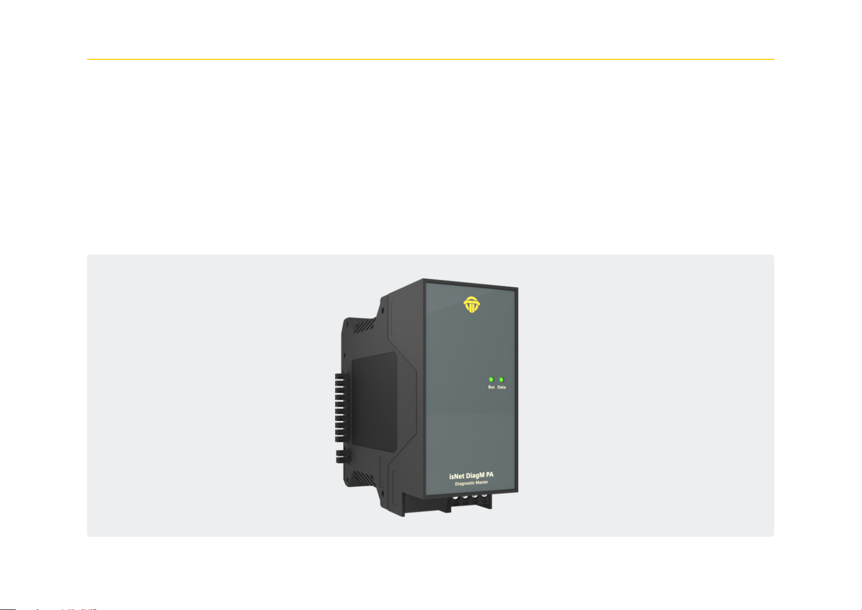
1.4 isNet DiagM PA
The isNet DiagM PA module is a Profibus Master with a PA physical
layer interface. It allows direct connection of Profibus PA field devic-
es without the need of a DP/PA converter. The module can serve as a
fieldbus power supply for the PA slaves or it can also be connected
to an existing and already powered PA segment as an additional
ma ster.
In combination with the isNet Lite the module can be used as a
gateway between Profinet and Profibus PA or as a Modbus-TCP
to Profibus PA converter. In parallel to process data exchange the
gateway allows access to the parameters of the PA slave devices
via FDT or OPC. Furthermore, the module contains some diagnostic
functionality like a protocol monitor that can run simultaneously to
the master to record data traffic for failure analysis, data logging or
other purposes.
15

1. 4.1 Technical details
1-Channel isNet DiagM PA
Connectors 1 screw terminals
Power consumption
LxWxH in mm 114,5 x 45
(2)
2,0W
(1)
x 99
Weight 250 g
Temperature range - 40 °C <= T
Storage temperature - 40 °C <= T
<= 60 °C / -40 °F <= T
amb
<= 85 °C / - 40 °F <= T
amb
<= 140 °F
amb
<= 185 °F
amb
Transmission rate 31,25 kbit/s
Driver software Windows XP, Vista, 7, 8 or 10
Delivery content Hardware, isNet DTM Library, Pactware, User manual isNet Line on CD
PA supply/channel 300 mA
PA supply voltage 22..24V
Order code 19300-1201
(1) Dimensions without lateral plugs
(2) without fieldbus slaves
16
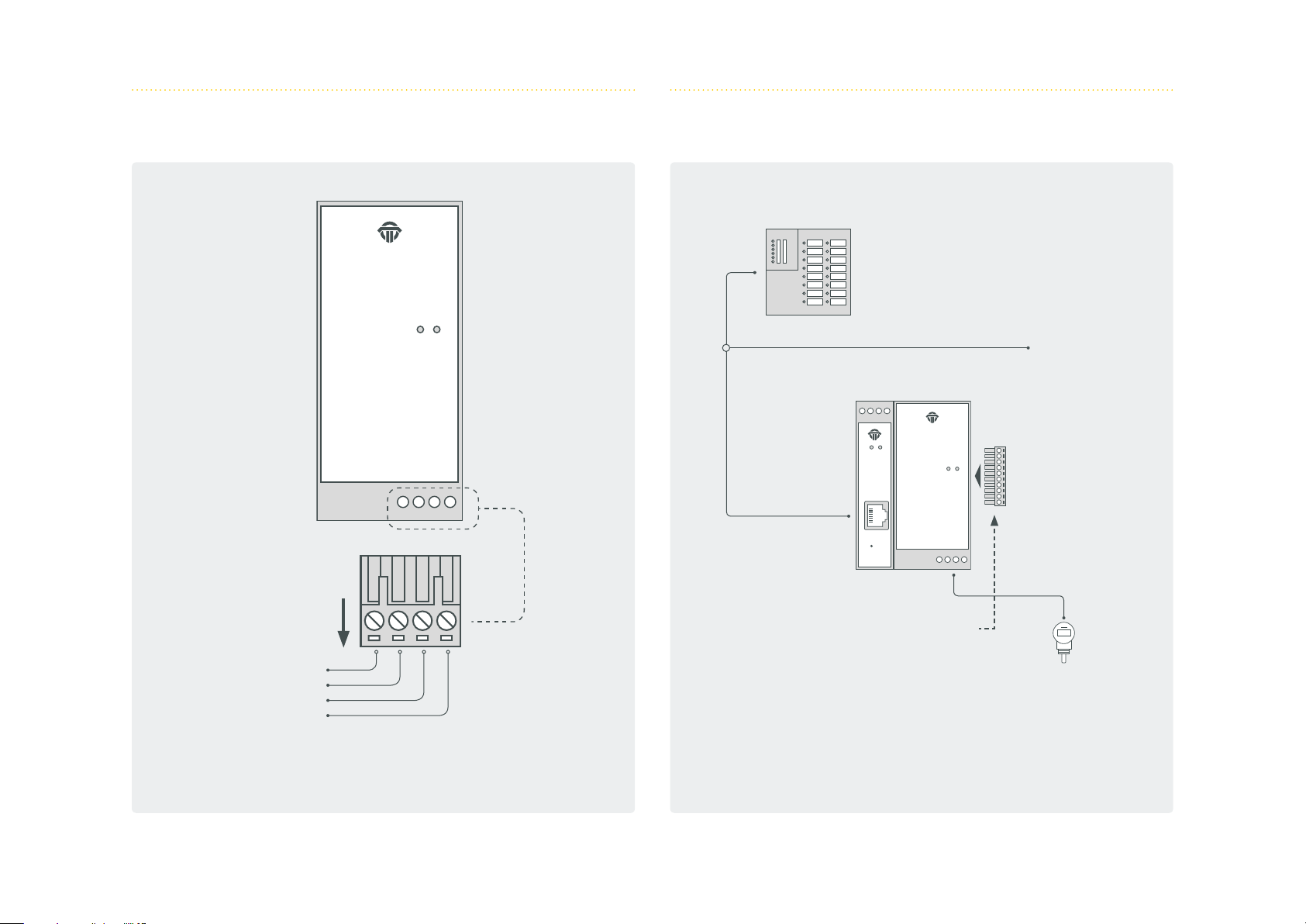
1.4.2 Channel assignment 1.4.3 Connection with a PLC
PNIO PLC
Shield
PA -
PA+
PA su pply
isNet DiagM PA
Diagnostic Master
BusData
PowerStatus
BusData
isNet DiagM PA
isNet Lite
Ethernet Gateway
Diagnostic Master
Termination plug in the last module!
PNIO
PROFIBUS PA devices
17

1.4.4 Hardware Installation
Profibus PA
power supply
or other
PLC/Profibus PA
master
PowerStatus
isNet Lite
Ethernet Gateway
PowerStatus
isNet Lite
Ethernet Gateway
data only,
no bus power
BusData
isNet DiagM PA
Diagnostic Master
Termination
isNet DiagM PA
Diagnostic Master
BusData
Profibus PA
9..36V from external power supply
Termination
Profibus PA
Connection with an external power supply
The PA modules enable you to connect to an existing PA network via
the signal lines PA+ and PA-.
Connection without an external power supply
The PA fieldbus devicescan be powered by the PA modules.
22...24V
Profibus PA
18
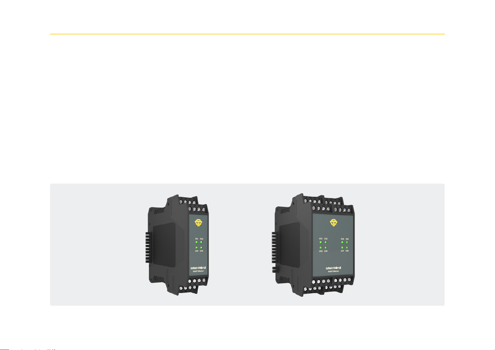
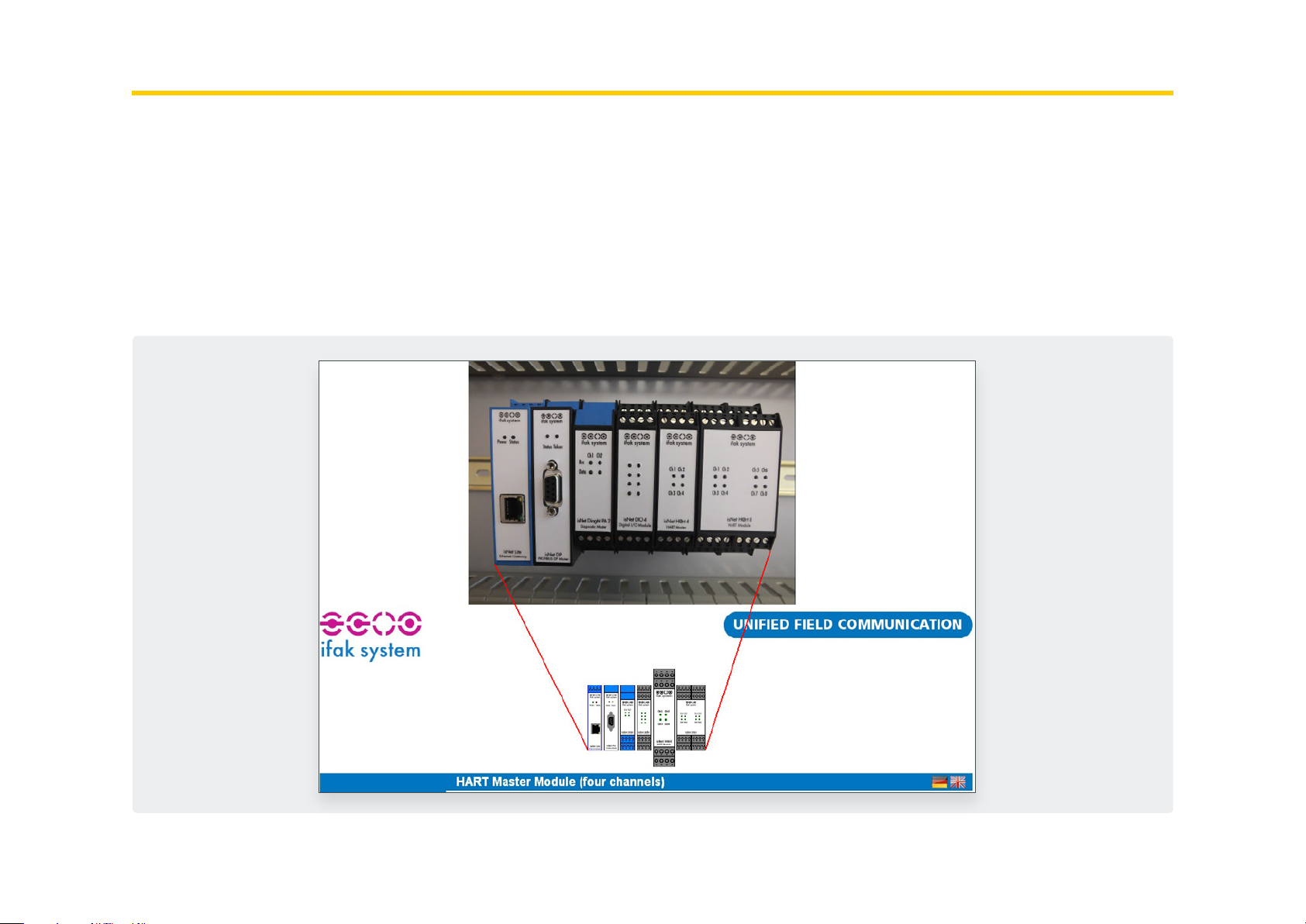
1.5 isNet H@rt
With the isNet H@rt Module the main module isNet Lite can be
extended to work as an HART-Ethernet-Gateway. The HART-Eth-
ernet-Gateway is an up-to-date option to replace the widely used
RS485 HART multiplexer solutions, as it enables the direct connec-
tion to the existing data network of a plant. The isNet H@rt modules
are equipped with either four or eight channels. Up to five HART
modules can be connected to the main module, so a maximum of 40
HART channels can be operated in parallel. Each channel provides
galvanic decoupling from the HART line. Access to the HART network
is achieved by screw-type terminals.
Wiring from the isNet H@rt module to an existing control loop is as
easy as connecting a mobile HART modem to the 2 HART wires. The
isNet H@rt module can be thought of as 4 (or 8) independent HART
modems in a single enclosure. Each HART channel must be connect-
ed in parallel to the 2 wires of the control loop regardless of its po-
larity. Depending on the input impedance of the Analog Input line
of the PLC a 240 Ohm communication resistor might be necessary.
This applies especially to Analog Inputs without HART capability,
which usually contain a small sense resistor with an input impedance
of about 10 Ohm. If the PLC is HART enabled, the 240 Ohm resistor
was already built in.
With the isNet H@rt CommDTM, the modules can be integrated in
your FDT Frame Application. Based on the HART over IP protocol,
access from the popular HCF OPC server is possible as well.
19

1. 5 .1 Technical details
4 - Channel isNet H@rt4 8 - Channel isNet H@rt8
Connectors 4 screw type terminals 8 screw type terminals
LxWxH in mm 114,5 x 22,5
(1)
x 99 114,5 x 45
(1)
x 99
Power consumption 1,2 W 1,4 W
Weight 140 g 250 g
Temperature range - 40 °C <= T
Storage temperature - 40 °C <= T
<= 70 °C / - 40 °F <= T
amb
<= 85 °C / - 40 °F <= T
amb
<= 158 °F
amb
<= 185 °F
amb
Transmission rate 1200 Bit/s
Pollution degree 2
Altitude up to 2000 m
Wire size 0,2 mm2 .. 2,5 mm2/AWG24..AWG 12
(4)
Driver software Windows XP, Vista, 7, 8 or 10
Delivery content Hardware, isNet DTM Library, Pactware, User manual isNet Line on CD
Order code 19300-0601 19300-0701
(1) Dimensions without lateral plugs
(4) Cable entries and field wiring must be suitable for an operating temperature of at least +20°C above ambient.
20
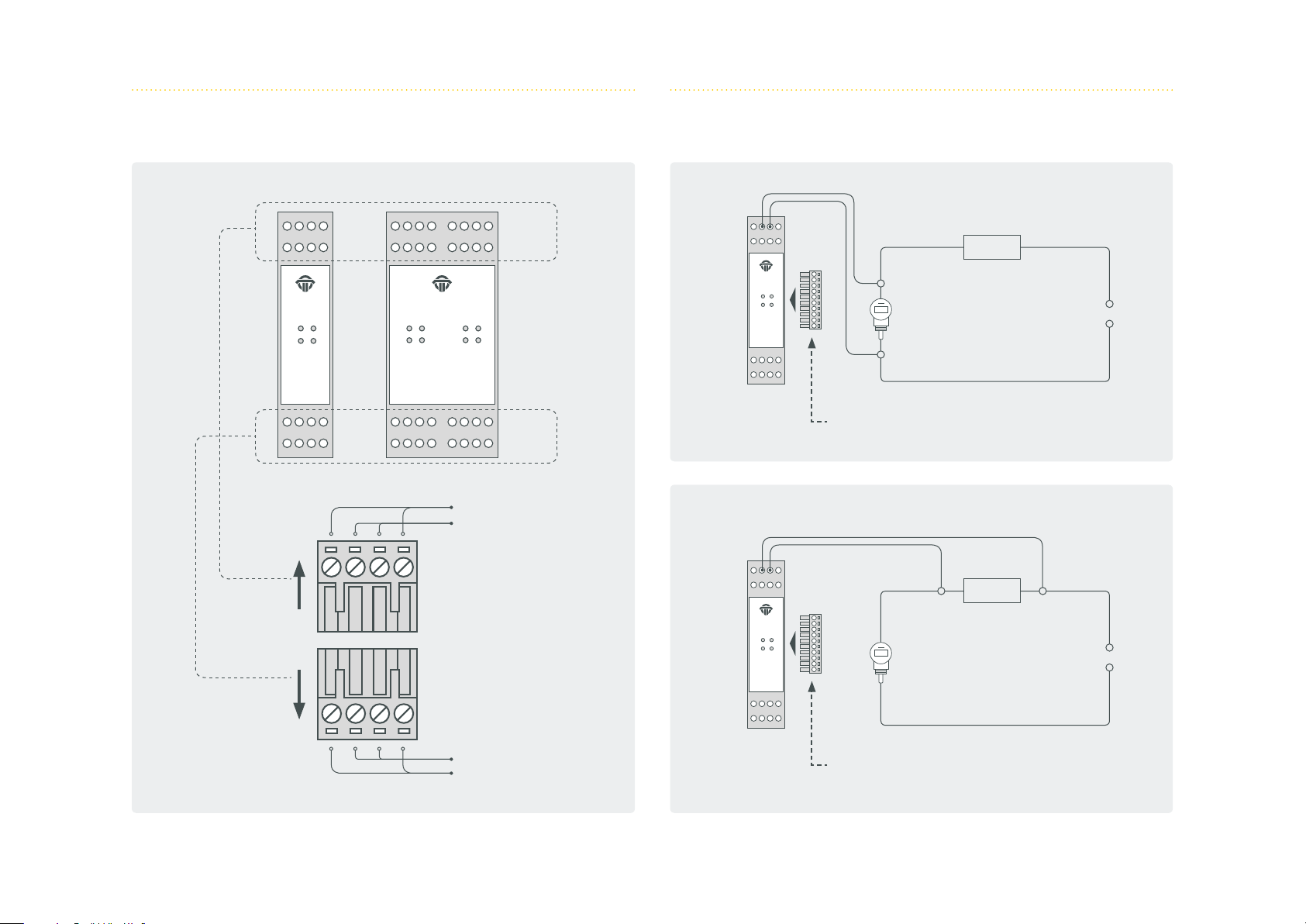
1.5.2 Channel assignment 1.5.3 Connection to a slave
Ch1Ch2
Ch3Ch4
isNet H@rt4
HART Master
Ch 1
Ch 2
Ch1Ch2
Ch3Ch4
isNet H@rt8
HART Master
Ch5Ch6
Ch7Ch8
Ch 5
Ch 6
Ch 3 Ch 7
Ch 4 Ch 8
Shield
HART
Ch1Ch2
Ch3Ch4
isNet H@rt4
HART Master
Master
Ch1Ch2
Ch3Ch4
isNet H@rt4
HART Master
240 Ω
Slave
Termination plug in the last module!
240 Ω
Slave
24 V
24 V
HART
Shield
Master
Termination plug in the last module!
21
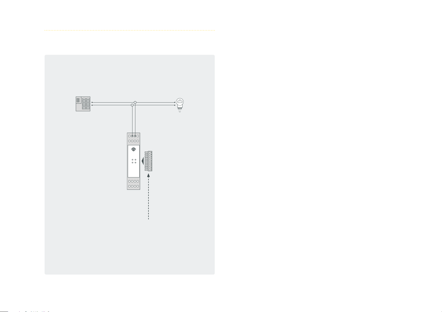
1.5.4 Connection with a PLC
Ch1Ch2
Ch3Ch4
isNet H@rt4
HART Master
Master
SlavePLC
Termination plug in the last module!
22

1.6 isNet H@rt+AI
The isNet H@rt8+AI module combines the HART master module with
4..20mA Analog Input functionality. The module provides 8 active AI
channels, which means the module will supply 24V DC to the HART
loops and thus power the connected HART instruments. The HART
instruments can be connected directly to the module, an external
loop resistor is not required as the input impedance of the AI chan-
nels already is 240 Ohms.
The measured analog values can be read by a connected PLC using
Modbus/TCP or Profinet. Due to the HART master functionality the
PLC has also access to the digital values of the HART instruments.
Additionally an engineering station can simultaneously access the
HART parameters of the connected HART instruments for configu-
ration, diagnosis or maintenance. This is possible with FDT based ap-
plications like PACTware, with OPC or with any other HART-IP client
applications.
23

1. 6 .1 Technical details
8 - Channel isNet H@rt8+AI
Connectors 8 screw type terminals
LxWxH in mm 114,5 x 45
Power consumption 1,8 W
(1)
x 99
(2)
Weight 250 g
Temperature range - 40 °C <= T
Storage temperature - 40 °C <= T
<= 70 °C / - 40 °F <= T
amb
<= 85 °C / - 40 °F <= T
amb
<= 158 °F
amb
<= 185 °F
amb
Pollution degree 2
Altitude up to 2000 m
Wire size 0,2 mm2 .. 2,5 mm2/AWG24..AWG 12
(4)
Transmission rate (HART) 1200 Bit/s
Transmitter supply voltage 24V
max. current 25 mA (per channel)
Input imperdance 250 Ω
Driver software Windows XP, Vista, 7, 8 or 10
Delivery content Hardware, isNet DTM Library, Pactware, User manual isNet Line on CD
Order code 19300-0702
(1) Dimensions without lateral plugs
(2) without fieldbus slaves
(4) Cable entries and field wiring must be suitable for an operating temperature of at least +20°C above ambient.
24
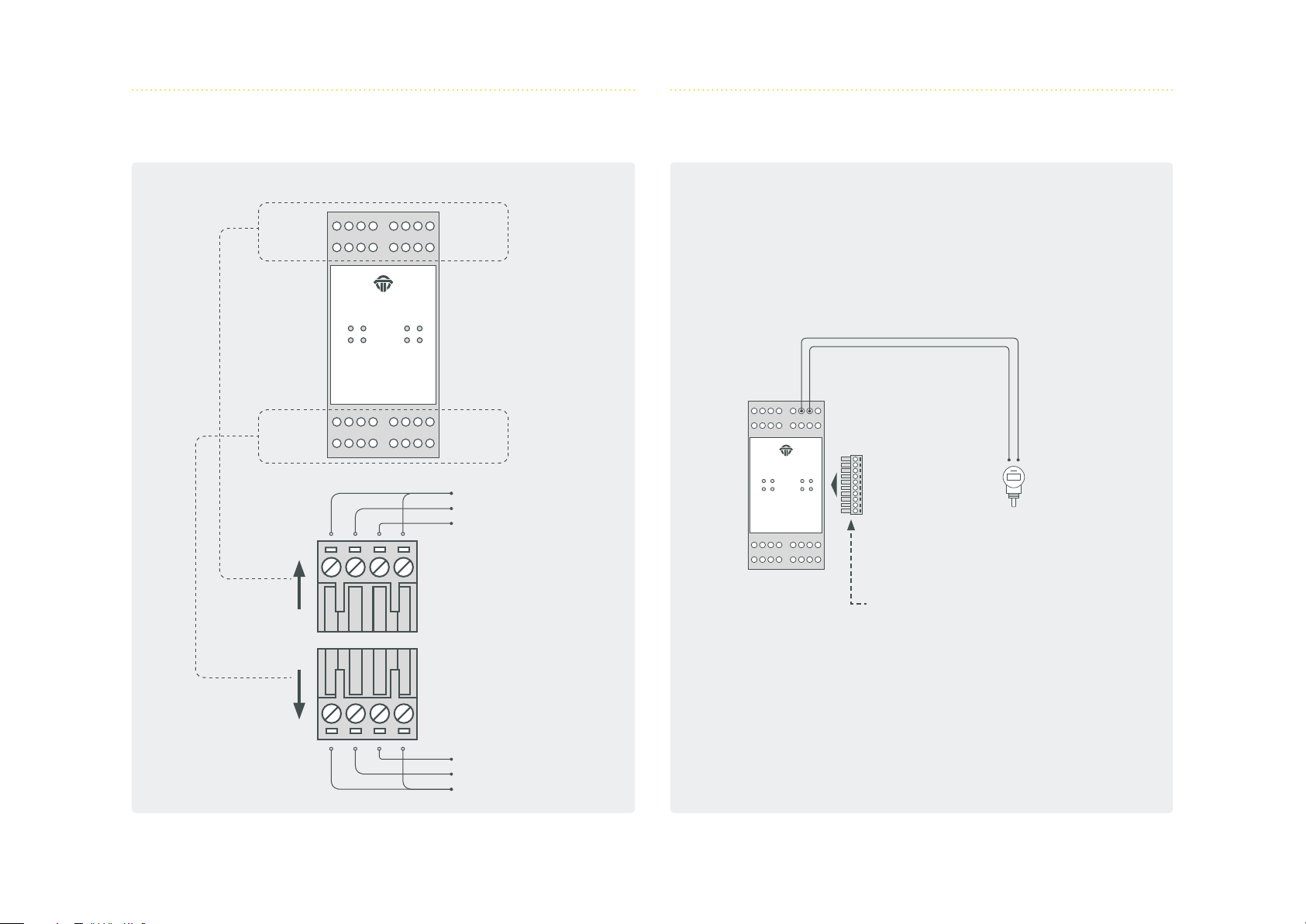
1.6.2 Channel assignment 1.6.3 Connection to a slave
Ch 1
Ch 2
Ch1Ch2
Ch3Ch4
isNet H@rt8+AI
HART Master
Ch5Ch6
Ch7Ch8
Ch 5
Ch 6
Ch 3 Ch 7
Ch 4 Ch 8
Shield
HART +
HART -
Ch1Ch2
Ch3Ch4
isNet H@rt8+AI
HART Master
Master
Ch5Ch6
Ch7Ch8
Slave
Termination plug in the last module!
HART HART +
Shield
25

1.7 isNet DIO
The isNet DIO is a Digital Input/Output expansion module for the
isNet Line. The module exists in 2 versions, one with 4 and one
with 8 I/O channels. Each channel consists of one 4-pin screw termi-
nal, with one Input and one Output per terminal. Every channel is
galvanically isolated individually.
The module does not only read or write binary logic levels, but every
channel can also be configured to operate with more sophisticated
functions like counter, timer, frequency measurement or PWM out-
put. The resulting process variables are directly accessible over
Profinet or Modbus-TCP.
26

1. 7.1 Technical details
4-Channel isNet DIO4 8-Channel isNet DIO8
Connectors 4 screw type terminals 8 screw type terminals
LxWxH in mm 114,5 x 22,5
(1)
x 99 114,5 x 45
(1)
x 99
Power consumption 1W 1W
Weight 140 g 250 g
Temperature range - 40 °C <= T
Storage temperature - 40 °C <= T
<= 70 °C / - 40 °F <= T
amb
<= 85 °C / - 40 °F <= T
amb
<= 158 °F
amb
<= 185 °F
amb
Pollution degree 2
Altitude up to 2000 m
Wire size 0,2 mm2 .. 2,5 mm2/AWG24..AWG 12
(4)
Order code 19300-1301 19300-1404
(1) Dimensions without lateral plugs
(4) Cable entries and field wiring must be suitable for an operating temperature of at least +20°C above ambient.
Digital Inputs
input voltage range -30V...30V
max. input frequency 100 Hz
switching levels
0:1:-30V...5V
15V...30V
Digital Outputs
ON
resistance:
maximum current:
< 1 Ohm
500 mA
OFF
resistance:
maximum voltage:
> 40 MOhm
30V
switching frequency 100Hz
27

1.7.2 Channel assignment
4 channel module
Ch 1 Ch 1
Ch 2 Ch 2
isNet DIO4
Digital I/O Module
8 channel module
isNet DIO8
Digital I/O Module
Ch 5
Ch 6
Ch 3 Ch 3 Ch 7
Ch 4 Ch 4 Ch 8
IN+
INOUT
IN+ IN- OUT OUT
OUT
ININ+
28

1.8 isNet PAMon and DPMon
With the isNet DPMon and isNet PAMon modules the head mod-
ule isNet Lite can be enhanced by diagnosis and protocol monitor
functions. The modules detects and diagnoses sporadically occurring
problems during data transmission on a PROFIBUS network. The
modules identifies configuration problems in the transmission proto-
col as well as electrical faults that cause interruptions.
The DP monitor module offers one channel that can be connected
to the PROFIBUS network via a D-SUB 9 connector. The PA moni-
tor module offers two channels working independently from each
other that can be connected to the PROFIBUS network via screwtype
terminals. Both monitor modules work totally passive; no telegrams
are sent to the bus. The modules evaluate the status of all stations
on the bus and provide a concise overview about it if needed. In this
view the bus status of every single layer of the OSI reference model
is separately detected and can also be addressed separately.
The modules also offer a protocol monitor, an integrated 200 MHz
oscilloscope and an extensive analysis of statistical data, e.g. error
counters or average time intervals. Long term monitoring allows au-
tonomous operation for a long period of time even if the Net Lite is
not connected to the PC. The protocol file is saved on a memory card
and can later be downloaded to a PC.
The accompanying software isField Diagnosis (see page 67) is used
to access the diagnosis functions.
29

1. 8.1 Technical details
isNet DPMon isNet PAMon
Connectors 1 RS-485 2 screw type terminals
LxWxH in mm 114,5 x 22,5
(1)
x 99 114,5 x 45
(1)
x 99
Power consumption 2,5W 2,4W
Weight 140 g 250 g
Temperature range 0°C <= T
<= 50°C / 32° <= T
amb
<= 122°F
amb
Transmission rate 9,6 kBit/s - 12 Mbit/s 31,25 kBit/s
Driver software Windows 2000, XP, Vista, 7,8 or 10
Hardware, isNet DTM Library, isFieldDiagnosis Setup, Pactware,
Delivery content
User manual isNet Line on CD
Order code 19300-0201 19300-0301
(1) Dimensions without lateral plugs
30

1.8.2 Channel assignment
PROFIBUS DPMon PROFIBUS PAMon
Shield
PA+
PA -
isNet DP Mon
DP Monitor Module
Ch 1
5
9
4
8
3
3 — Channel B
5 — Ground
6 — +5V
8 — Channel A
Ch 2
7
2
6
1
isNet PAMon
RS-485MMC Slot
PROFIBUS PA Monitor
MMC Slot
31

1.9 isNet FFMon
With the isNet FFMon module, the main module isNet Lite can be
enhanced by new diagnosis and protocol monitor functions. The
modules detects and diagnoses sporadically occurring problems
during data transmission on a FOUNDATION FIELDBUS network. The
modules identifies configuration problems in the transmission proto-
col as well as electrical faults that cause interruptions.
The FF monitor module offers two channels working independently
from each other that can be connected to the FOUNDATION FIELD-
BUS network via screwtype terminals. The monitor work totally
passive, no telegrams are sent to the bus. The module evaluates the
status of all stations on the bus and provides a concise overview
about it if needed. In this view the bus status of every single layer
of the OSI reference model is separately detected and can also be
addressed separately. The module also offers a protocol monitor, an
integrated oscilloscope and an extensive analysis of statistic data,
e.g. error counters or average time intervals. Long term monitoring
allows autonomous operation for a long period of time even if the
isNet Lite is not connected to the PC. The protocol file is saved on a
memory card and can later be downloaded to a PC.
The accompanying software isField Diagnosis (see page 67) is used
to access the diagnosis functions.
32

1.9.1 Technical details
isNet FFMon
Connectors 2 Screw terminals
LxWxH in mm 114,5 x 45
(1)
x 99
Power consumption 2,4W
Weight 250 g
Temperature range 0°C <= T
<= 50°C / 32° <= T
amb
Transmission rate 31,25 kBit/s
Driver software Windows 2000, XP, Vista, 7, 8 or 10
Hardware, isNet DTM Library, isFieldDiagnosis Setup, Pactware,
Delivery content
User manual isNet Line on CD
Order code 19300-0801
(1) Dimensions without lateral plugs
<= 122°F
amb
33

1.9.2 Channel assignment
Shield
FF H1FF H1+
Ch 1
isNet PAMon
PROFIBUS PA Monitor
MMC Slot
Ch 2
34

2. Hardware installation
2.1 Safety instructions
Installation notes
Installation, operation and maintenance must be made by qualified personnel only and in accordance with your local
and national technical regulations and safety directives.
Do not repair the device yourself, but replace it with an equivalent device. Repairs may be performed by the manu-
facturer only.
The manufacturer is not legally responsible for damage resulting from failure to comply.
35

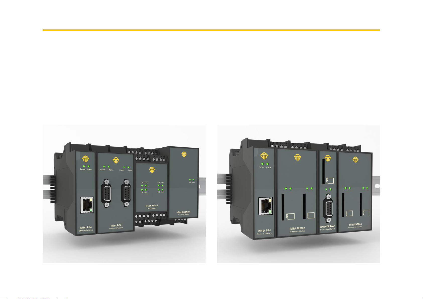
2.2 Mechanical installation
Starting from the left there is always mounted the main module is-
Net Lite. To the right of isNet Lite up to 5 expansion modules can be
connected. A termination plug (standard accessory) has to be placed
isNet Lite
Ethernet Gateway
PowerStatus
at the last expansion module. This termination plug is not intended
to connect wires. It contains two resistors that are necessary for com-
munication between head module and expansion modules.
max. 5 expansion modules
Status Token
isNet DP
Profi bus DP Master
isNet DiagM PA
Diagnostic Master
BusData
isNet DIO4
Digital I/O Module
Ch1Ch2
Ch3Ch4
isNet H@rt8+AI
HART Master
Ch5Ch6
Ch7Ch8
Ch1Ch2
Ch3Ch4
isNet H@rt4
HART Master
head module always isNet Lite termination plug at end
36

2.2.1 Specific conditions of use
The equipment shall be installed in an enclosure that provides a degree of protection not less than IP 54 in accordance
with IEC/EN 60079-15 and that have been considered to be not accessible in normal operation without the use of a tool.
Transient protection shall be provided that is set at a level not exceeding 140 % of the peak rated voltage value at the supply termi-
nals to the equipment.
The modules must be mounted vertically on a 35mm DIN rail.
The modules of the isNet Line are an open system and in accordance with UL / CSA approval an “open type.” The mod-
ules have to be installed in a control cabinet, appropriate housing or a closed electrical operation room accessible only
to authorized maintenance staff.
37

2.3 Electrical installation
Before installation of the modules and wiring make sure that the system is off power.
The supply voltage of 24V is only connected to the main module isNet Lite. The expansion modules are supplied via the backplane bus from the
main module.
To supply the modules only power supplies with a secure electrically isolated extra-low voltage (SELV) may be used.
Cable entries and field wiring must be suitable for an operating temperature of at least +20°C above ambient.
Please note:
The isNet Lite head station and your PC need to be in the same IP-address range and therefore in the same subnetmask. If your PC can not
locate the isNet Lite it could be due to a firewall. The PC is using UDP broadcasts to locate the isNet Lite. There could also be an issue with UDP
broadcast if you have two or more Ethernetcards in your PC.
38
3. Web Interface
The isNet Lite provides a web interface for startup operation, set-
tings and maintenance. The layout consists of a top area with a view
of the actual module configuration, a menu on the left side that is
depending on the currently selected module and an information/
settings area. On the top of the page the website shows the actual
configuration of all modules currently connected to the isNet Lite. If
the pictures do not match the actual module configuration, then the
isNet Lite was not able to recognise the attached modules correctly.
In this case please check the termination plug (see ch. 2 “Hardware
installation”). The pictures are clickable to select the fieldbus mod-
ules. Depending on the selected module the menu on the left side
will show menu items related to the kind of the selected module.
39

3.1 Configuration of the IP address
The default address of the module is: 192.168.0.10 subnet mask
255.255.255.0 Use your favorite browser to go the IP Address of
your isNet Lite Headstation. You should see this website. This is a
overview over the current status.
Click on „Network Settings“ and you will get to the configuration
mask.
Here you can change the Hostname, the IP Address, the subnet
mask and the default Gateway. You can also choose to set the IP
Address manually or with your DHCP Server. Pressing the Submit
button applies the changes and restarts the headstation.
40
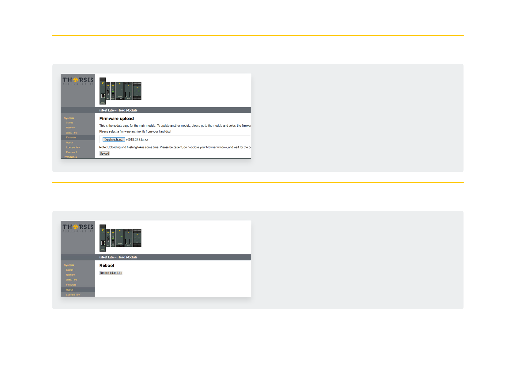
3.2 Update of the Firmware
3.3 Soft-Restart
If a new firmware is available for your device you can flash it
using the web interface. Go to the Menu Firmware and select the
file you want to flash. Click the Upload button and wait until a
confirmation appears that the upload was successful.
After the succesful update, the isNet Lite must be restarted by
using the Restart function in the Web interface.
To restart the module, go to the Restart menu and press the but-
ton Reboot.
41

3.4 Password Protection
To enable a global password protection for the isNet Lite web
interface, click on the Password menu on the left. Activate the
Password protection by clicking in the checkbox. Enter your pass-
word and repeat it in the field below.
Click Apply to confirm your settings.
Please note, that the username is always admin and can not be
changed.
42

3.5 Activating MODBUS functionality
To unlock the MODBUS functionality, you need to enter a valid
license code. Go to the License Key page and enter the key. After
clicking Apply, the MODBUS feature will be activated. Enable the
MODUBS gateway by clicking Activate MODBUS Gateway.
43

3.6 MODBUS status
The menu MODBUS Gate shows an overview of the MODBUS sta-
tus. You can upload a FCML configuration file here.
44

3.7 HART over IP
Enable or disable HART over IP at this menu. It also shows the cur-
rent status of the HART over IP functionality.
45

4. FDT Configuration
We also provide a CommDTM for FDT Frame Applications. To
install the CommDTM you need to install the „isNet H@rt DTM
Setup.exe“ from the CD-Rom. After that you have to start your
FDT-Frame Application and it will update its DTM database.
The FDT Frame Application PACTware is used in this manual as an
example. Once you have opened your FDT Frame Application and
started a new project you can add the isNet Lite as device. You
just need to select it and it will be added to your project.
46
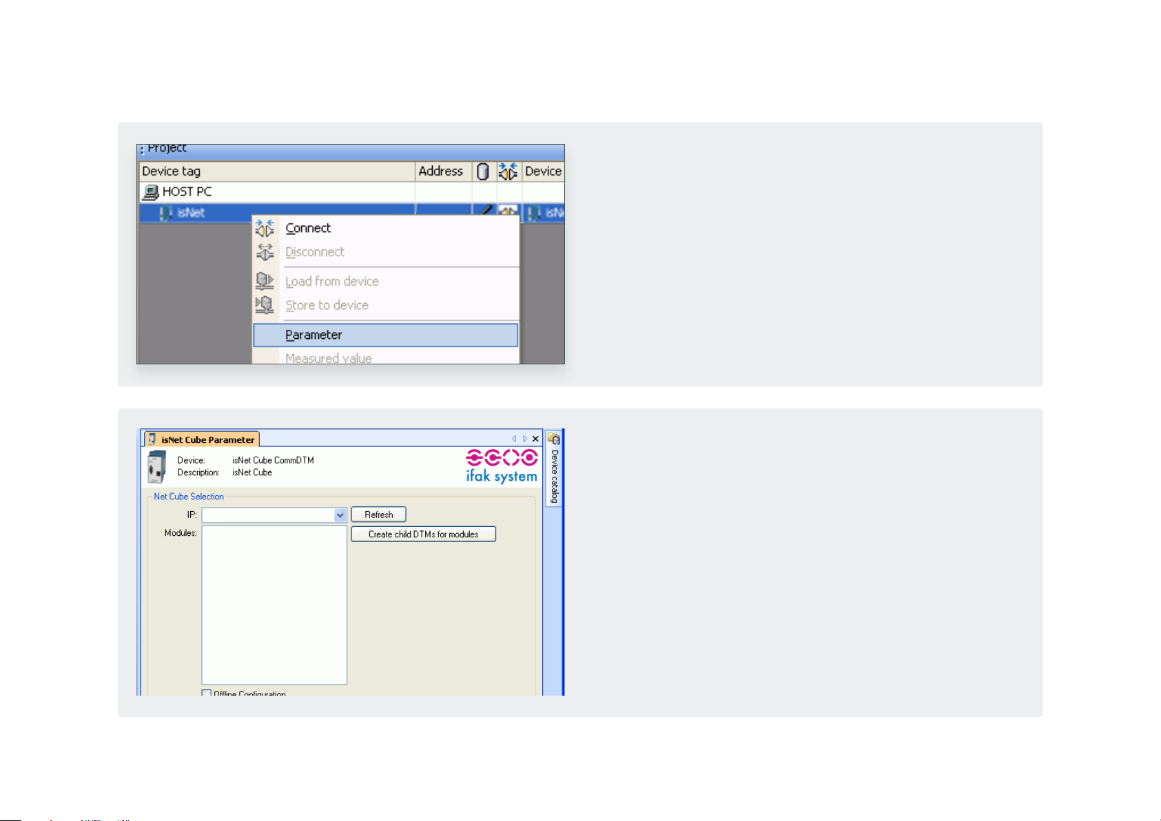
The next step is to right click on the isNet Lite and select Parame-
te r.
You can now select the correct IP address of the isNet Lite. Just
click on the Drop-Down-List as shown. The dialog will show all
attached modules. If you click on „Create Child DTM“ they will be
added to your project below the isNet Lite.
If you are using Fieldcare instead of PACTware this process might
fail and you need to add them manually.
47
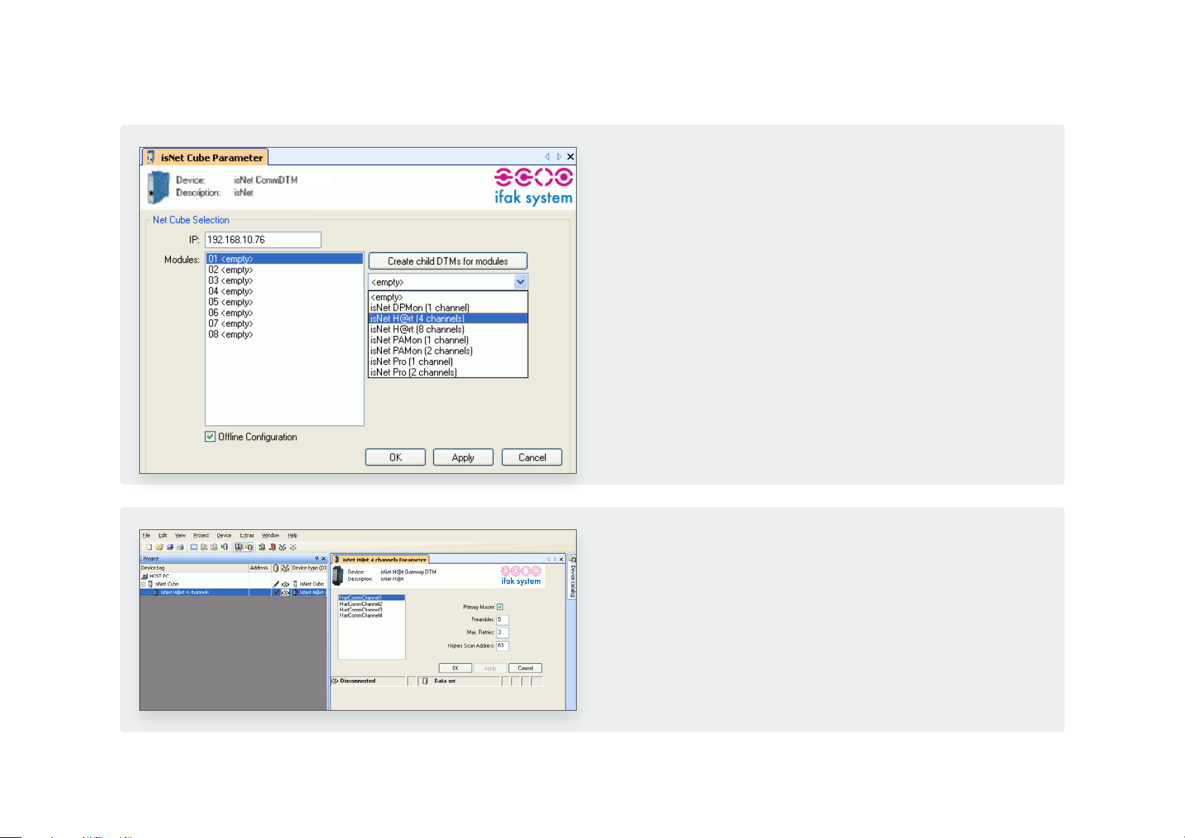
If the CommDTM could not find any isNet Lites or if the isNet
Lite is offline you are able to configure it offline. You just need
to click the check box „Offline Configuration“. Then enter the IP
address manually and select the attached modules in the right
order manually.
Add a Child DTM to the isNet DTM if not done previously. The De-
vice catalouge will off a list of installed isNet Lite modules. Select
the right module type and, after that, open the Parameter dialog
to make the fieldbus related settings.
48

Now you can add a DeviceDTM to the isNet DTM. A dialog will
show up where you can select the physical channel to which the
device is connected.
49

5. isNet Lite – PROFINET
The PROFINET Gateway is a combination of the Ethernet headstation
isNet Lite and the proven PROFIBUSand HART-master expansion
modules of the product line. The implementation of the gateway
firmware was done according to the profile „Fieldbus Integration
into PROFINET IO 2.0“ of PROFIBUS International.
By means of a corresponding GSDML, it is easily integrated into
PROFINET-based automation solutions. By connecting the corre-
sponding fieldbus modules, up to 40 HART or 10-PROFIBUS-channels
are available.
A particular highlight are the expansion modules isNet PA2 and
PA4, which allow a direct connection to up to 4 PA lines per module.
Together with the isNet Lite, the process area on the field level can
be directly accessed through the PROFINET backbone. The previously
required use of a DP / PA segment coupler is no longer necessary.
50

5.1 Workflow of the engineering process
GSD
GSD GSD
GSD
ML
Since the isNet PNGate is a modular gateway, there is no unique
GSDML file available for this gateway. In fact the user needs to
create the GSDML file before working with the engineering tool
of his PLC, dependig on the actual hardware configuration and
depending on all used PROFIBUS slaves in the end user applica-
tion. Luckily with the “isNet PNGate Config tool” this is a rath-
er simple step. The user simply adds isNet Line modules to his
project, so that the setting matches his hardware configuration
attached modules. Then, in case of PROFIBUS, the user imports all
necessary GSD files just by drag and drop them into the applica-
tion window. One more single button creates the GSDML file.
PLC
The picture on the left illustrates the whole workflow of the engi-
neering process.
51

5.2 Creation of the GSDML file
With the „isNet PNGate Config tool“ the creation and configu-
ration of a GSDML file is a quite simple step. The tool consists of
a single, stand-alone executable file and does not need to be in-
stalled on the PC. It can be run directly from the CD or any other
storage medium.
52

5.2.1 Step 1: Configuration of modules
The user needs to add modules to the project to match the con-
figuration with the actual hardware of isNet Line modules. Add-
ing modules is possible by using the context menu on the isNet
Lite picture (the Ethernet head module) or by opening the mod-
ule catalog and clicking on the desired module.
Module catalog opened
53
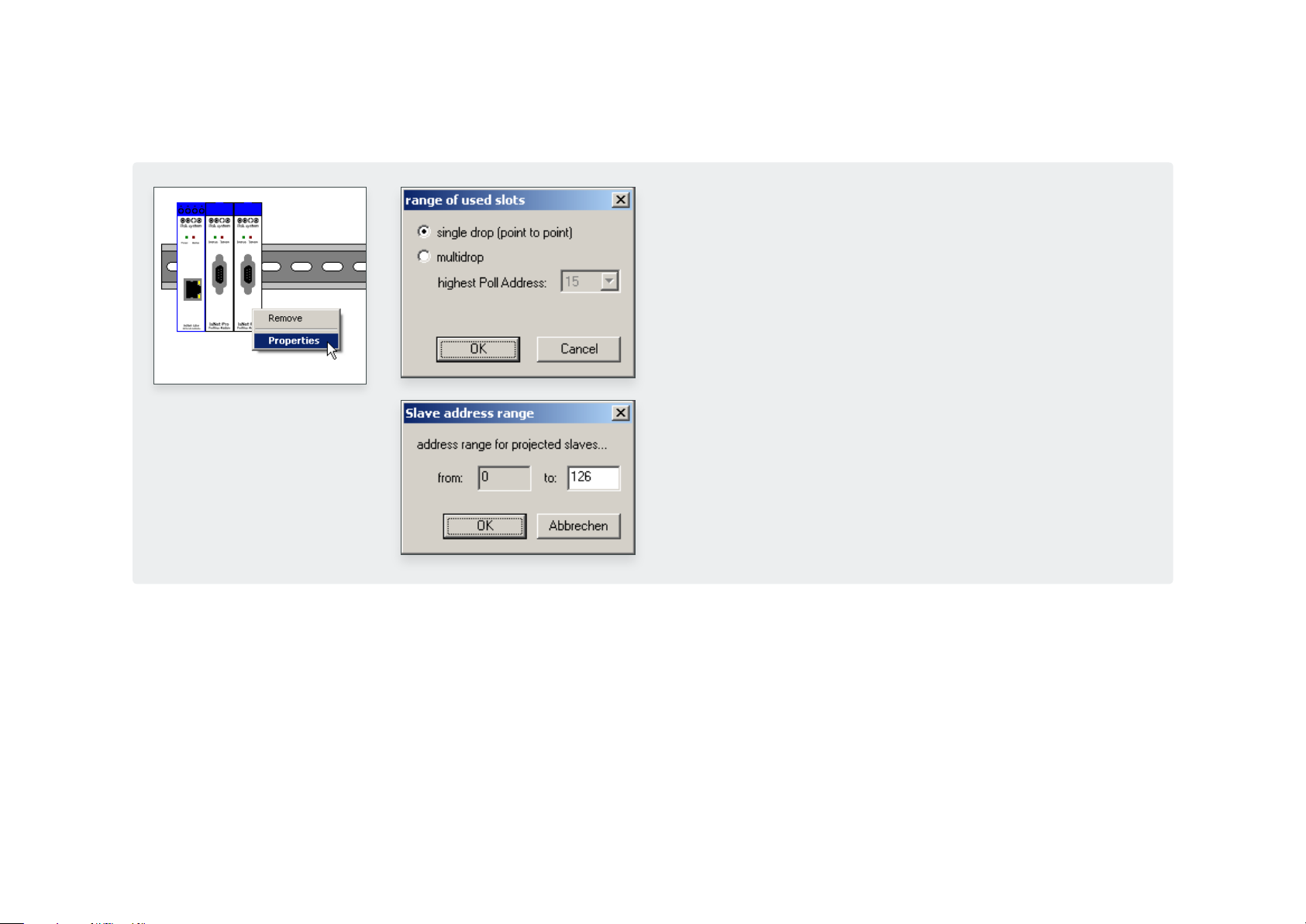
To limit the number of PROFINET slots for better ressource usage,
the user can set limits to the address range used by PROFIBUS
and/or HART modules (in case of multidrop). By using the context
menu (or doubleclick) on the appropriate module, the corre-
sponding dialog window will open.
To remove a module from a configuration, just open the context
menu on the module and select “Remove”.
According to the „Fieldbus Integration into PROFINET IO 2.0“ guide-
line of PROFIBUS International, every field device (e.g. PROFIBUS
slave) occupies one PROFINET Slot in the final engineering project.
With up to 126 possible slave addresses for PROFIBUS, one single
module like the 4 channel “isNet PA4” module might occupy up to
more than 500 PROFINET slots, and with up to 5 supported modules
in the project, the total amount of PROFINET slots might increase to
much more than supported by small PLCs. Therefore is might be nec-
essary to limit the address ranges of the attached Fieldbus modules.
54
5.2.2 Step 2: Configuration of PROFIBUS slaves
To make use of PROFIBUS slaves, the user needs to import the nec-
essary GSD files into the GSDML project. This is possible by using
the menu item “Import GSD...” of the “File” menu, by clicking on
the appropriate toolbar button or by dragging the GSD files from
any Explorer window of Windows into the slave list frame of the
“isNet PNGate Config tool”. Please note that the slave list frame
remains disabled as long as there is no PROFIBUS Mastermodule
added into the project configuration.
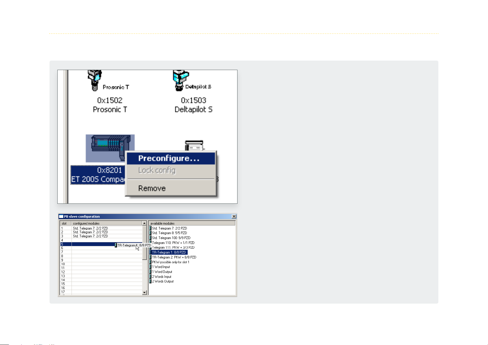
By using the context menu or by doubleclick on the PROFIBUS
slave icon, the user may preconfigure the modules of the PROFIB-
US slave.
Preconfiguration is useful if the user has several slaves of the
same type in the final engineering project, all with the same
module configuration. Preconfiguration saves him to configure
every single slave in the engineering tool of the PLC.
55
5.2.3 Step 3: Export of the GSDML file
Export of the GSDML file is done with a single mouse click on the
appropriate toolbar button or by using the “Export GSDML...”
menu item of the “File” menu. The following “Save as...” dialog
already suggests a proper file name for the GSDML file.
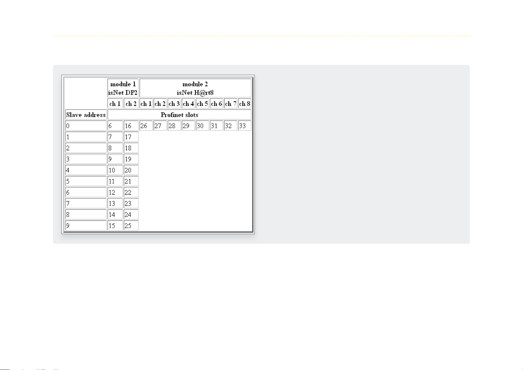
Together with the GSDML file the tool generates 2 more files.
One file is the symbol picture, that is used in the engineering tool
to be displayed for the isNet PNGate. The other file is a HTML
page with a table, that tells the user the relationship between
fieldbus slave address of the underlying fieldbusses and PNIO
slots in the enginering tool of the PLC.
56

5.3 Integration in SIMATIC Manager
After creation of the GSDML file, the user can start the engineering process in the engineering tool of his PLC.
This chapter shows this process with the example of SIMATIC Manager.
5.3.1 Import of the GSDML file
In the SIMATIC Manger project please open the HW Config Win-
dow by double-clicking on the Hardware item.
57

In the HW Config Windows please select menu item „Options ->
Install GSD file...“.
In the following Dialog browse to the folder on your storage
medium with the GSDML file, select the GSDML and select the
button „Install“.
58

After Installation of the GSDML file, the isNet PNGate will appear
in the Hardware catalog with all underlying modules and sub-
modules.
59

5.3.2 Setting up properties for isNet PNGate
After adding the isNet PNGate into the engineering project, se-
lect the menu item „Object Properties...“ from the context menu
to change PNIO Device name and IP address of the PNIO device.
The device name must match the device name, that is stored in
the isNet Lite. The Device name can be found on the website of
the isNet Lite (please refer to „3. Web Interface“ on page 30).
60

It is recommended to check the Update time for the is- Net PN-
Gate. To do so, please select the PROFINET line in the SIMATIC
manager and open the context menu. After selection of menu
item „Object Properties...“ from the context menu, a dialog win-
dows opens, where the Update time can be edited. The Update
time should be set to 128ms.
61

5.3.3 Setting up PROFIBUS
To change the baud rate of a PROFIBUS segment, the Master ad-
dress or any other bus parameter, please open the context menu
of the channel of the PROFIBUS module and select menu item
„Object Properties....“.
62

5.3.4 Adding fieldbus slaves to the engineering project
In the hardware catalog, the PROFIBUS slaves and HART slaves
appear as modules under the isNet PNGate. To add a fieldbus
slave to the project, just drag it into a slot of the isNet PNGate.
To determine the appropriate PROFINET slot, the „isNet PNGate
Config tool“ also creates a HTML page with a table, that tells
the relationship between fieldbus slave address and PNIO slots
(please refer to 5.2.3 for an example). If e.g. there is a PROFIBUS
slave attached to channel 1 of module 1 with PROFIBUS slave
address 3, then the corresponding slot is 9, so the user needs to
drag the slave to slot 9. After adding the PROFIBUS slave into the
appropriate PROFINET slot, the slave modules need to be added
to the project. All PROFIBUS slave modules will appear as sub-
modules in the hardware catalog. To add PROFIBUS slave modules
to the project, these submodules need to be dragged into the
corresponding subslots of the slave. To skip this step, the slave can
be preconfigured in the „isNet PNGate Config tool“ (see chapter
5.2.2).
63

In the next example there is a HART slave attached to the HART
module at channel 4. According to the example in chapter 5.2.3
the user needs to drag the HART slave into slot 29.
64
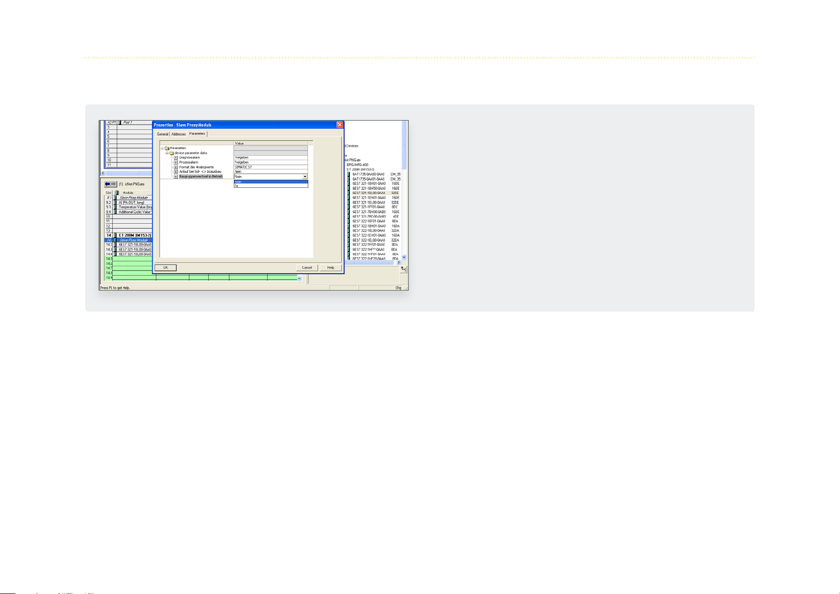
5.3.5 Parameterisation of PROFIBUS slaves and PROFIBUS modules
If a PROFIBUS slave provide user specific parameter
data, these parameters can be changed. To do so,
please double-click on the module or select menu
item „Object Properties...“ in the context menu of the
module.
65

6. isNet Lite – Modbus
The Gateway isNet Lite is suited for varied tasks in remote opera-
tion. Modbus functionality can be enabled in the web interface.
See chapter 3 on page 30 for details. Device parameterization,
network configuration or diagnosis, data logging and remote
control can be done directly from the workstation. The isNet Lite
acts as a head module. Up to 5 fieldbus-specific modules (PROFIB-
US PA, DP, and HART) or digital I/O modules can be connected, a
free combination of the modules is supported. The PROFIBUS DP
modules are equipped with one or two bus interfaces (single/dual
module), PROFIBUS PA with up to 4 and HART supports up to 8
bus interfaces.
For a detailed description of the Modbus functionality and map-
ping tables, please see the Thorsis Technologies Modbus manual.
66
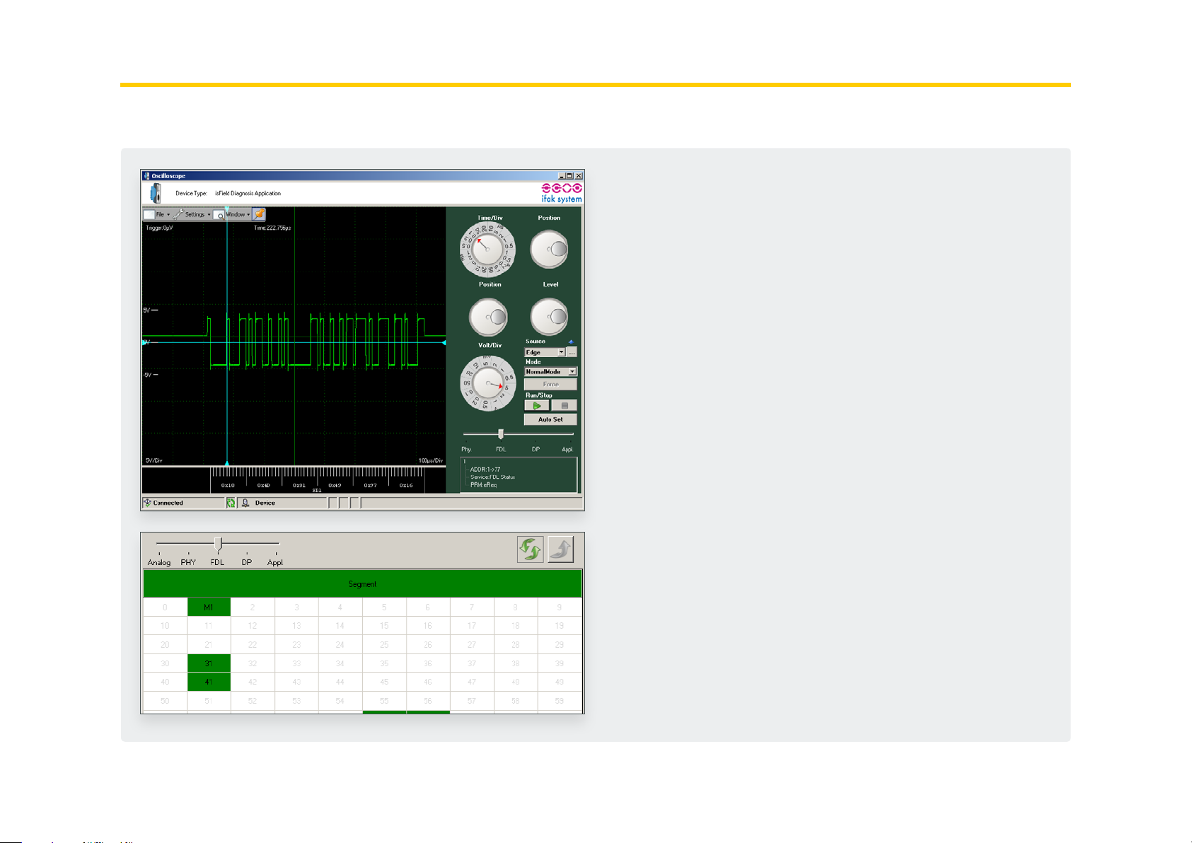
7. isFieldDiagnosis
Every isNet Monitoring module comes with the Diagnosis Soft-
ware DTM isField Diagnosis. The Software shows the status of
all stations on the bus and provides a concise overview about
it if needed. In this view, the bus status of every single layer of
the OSI reference model is separately detected and can also be
addressed separately. The software also offers a protocol monitor,
an integrated oscilloscope and an extensive analysis of statistic
data, e.g. error counters or average time intervals. Sophisticated
filter and trigger possibilities restrict the data volume and allow
for tailored start and stop conditions of the monitoring.
For a detailed description of the Diagnosis functionality, please
see the Thorsis Technologies isFieldDiagnosis manual.
67
8. Document History
Version Date Description
1.0 05.09.18 initial version
1.1 21.11.18 new texts & images
© Last changed 11. March 2019
Thorsis Technologies GmbH
Oststr. 18
39114 Magdeburg
Germany
Tel +49 391 544 563-1000
Fax +49 391 544 563-9099
info@thorsis.com
www.thorsis.com
68
 Loading...