

Thornycroft 90, 108 Owner's Manual

BS 5514/1.
MARINE ENGINES
The Thornycroft 90 and 108 engines are both 4 cylinder, 4 stroke naturally
aspirated high speed diesel units, both engines having electrically operated heater
plugs to aid cold starting.
The cast iron crankcase with ribbed sidewalls houses a forged steel, fully
counterbalanced crankshaft carried in three or five bearings respectively.
A full pressure wet sump lubrication system is employed with a full flow
detachable element type oil filter and integrated lubricating oil cooler.
The cooling system is indirect and usually employs an engine mounted heat
exchanger with a belt driven raw water pump. This system is known as IFWC
(internal fresh water cooled).
An optional system is EFWC (external fresh water cooled.) This system utilizes the
engine fresh water pump and usually employs skin tanks attached to the hull to serve as heat
exchangers.
The single belt driven alternator and fresh water pump drive include a manual
belt tensioning arrangement for low maintenance completes the comprehensive
engine package.
90 108
4 Cylinder naturally aspirated 4 Cylinder naturally aspirated
Power intermittent at 3500rpm = 36BHP Power intermittent at 3500rpm = 47BHP
continuous at 3000rpm = 30BHP continuous at 3000rpm = 38BHP
Maximum torque at 2400rpm = 731bf ft
Maximum torque
Idle speed
at 2500rpm = 531bf ft
= 570rpm
Idle speed = 570rpm
Minimum full load speed = 1500rpm
ENGINE RATINGS
Minimum full load speed = 1500rpm
The type 90 Engine may be set to develop continuous outputs from 13.5 to 30 BHP according to
requirements
The type 108 Engine may be set to develop continuous outputs from 21 to 38 BHP
according to requirements.
For special applications where full power will not be required for periods in
excess of 1 hour in any 12 hours consecutive running the engine can be supplied at an
intermittent rating as shown above.
NOTE: All horsepower ratings quoted are at the engine flywheel. Due allowance must
be made for transmission losses which will depend on the type of gearbox fitted.
For tropical use it is necessary to derate the engine by 2% for each 5%°C (10°F)
above 30°C (85°F) air temperature at sea level. In some parts of the world
further derating for humidity is necessary in accordance with

INITIAL STARTING OF ENGINE
PAGE
_. Engine mounting and dipstick marking. Filling engine with oil.
2. Lubricant specification for engine and gearbox. Filling gearbox.
3. Coolant/Corrosion inhibitor specification. Filling cooling system.
4. Priming the engine oil system.
5. Bleeding the fuel system type 90 engines.
6. Bleeding the fuel system type 108 engines.
7. Initial start. Normal start. Running in.
8. Operating guidelines.
9. Operating guidelines.
MAINTENANCE
Maintenance schedule.
Engine oil and filter change
Engine oil and filter change
Fuel filter change. Cleaning
fuel lift pump. Gearbox oil
change. Cleaning air filter.
Alternator drive belt adjustment
and replacement. Raw water pump
adjustment and replacement.
Checking and setting valve
clearances. Procedure for
retorquing cylinder head nuts. Removal/Refitting
fuel injectors.
Changing coolant.
Draining raw water system.
External fresh water cooled engines.
Electrical system.
Fault finding.
Fault finding.
Laying up the engine.
Re-commissioning.
Notes.
10.
11.
12.
13.
14.
15.
16.
17.
Type 90 engines.
Type 108 engines.
18.
19
20.
21.
22.
23.
24.
25.
26.
27.
28.
29.

THORNYCROFT
Page 1
CHECKING ENGINE MOUNTING
The maximum installed angle of the engine is 15°, engine types 90/2, 108 and 108/2
(10° for engine type 90). This allows for a further rise of 4° when the craft is
moving. Check the angle of installation using the centreline of the mounting feet
bolts as a datum. Measure vertically on the centreline of the underside of the
front mounting foot bolt to find the angle of installation Fig. 1
Fig. 1
Horizontal Line
Type 90 Type 90/2 Type 108
A 93mm = 10° A 138mm = 150 A 136mm = 15°
46mm = 5° 93mm = 10° 91mm = 10°
46mm = 5° 46mm = 5°
MARKING DIPSTICK, FILLING WITH OIL
Your engine is despatched from the factory without engine or gearbox oil and with an
unmarked engine dipstick. After the boat is launched, and is resting at
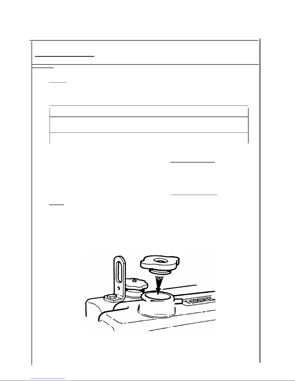
its normal trim angle, remove the oil filler cap from the rocker box Fig. 2 and pour 3.9
litres for type 90, 4.5 litres for type 90/2 or 4.8
litres for type 108 of specified lubricant through the filler
hole. Allow 5 minutes for .the oil to drain into the sump,
withdraw the dipstick and mark it for maximum oil level Fig.
3 (Use a centre punch for marking as filing a notch can
cause fatigue and eventual breakage while the engine is
running). Then mark dipstick using the same method 12.7mm
(%") below the maximum mark and this will be the minimum
level.
CHECKING ENGINE MOUNTING,
MARKING DIPSTICK, FILLING ENGINE WITH OIL


LUBRICANT ENGINE AND GEARBOX
`Page 2
ENGINE OIL
RUNNING IN OILS
Do NOT use special running-in lubricating oils for new or rebuilt engines. Use the
lubricating oils specified for normal engine operation.
ENGINE OIL VISCOSITY RECOMMENDATIONS
The use of a multi-graded lubricating oil has been found to improve oil
consumption and improve engine cranking in cold temperatures while maintaining
lubrication at high operating temperatures. A multi-grade oil conforming to
MIL-L-20104B is. recommended with the viscosity grades shown in Fig. 4. The use of
single grade lubricating oil is not recommended except for synthetic oils used
in arctic conditions.
Atmospheric Temperature Viscosity
Above -10°C 20W50
-20°C to 10°C 1OW30 or 1OW40
Below -10°C 5W30 or 5W40
Fig. 4.
GEARBOX OIL
Borg Warner
Automatic Transmission Fluid
(Type A)
Hurth
Automatic Trnamsission Fluid (Type A)
Newage PRM SAE 20 Engine Oil Minus 18°C to 0°C
SAE 30 engine Oil Above 0°C
FILLING THE GEARBOX
Remove the oil filler plug combined dipstick from the top of the gearbox. This is
in approximately the same position on Hurth, Newage PRM and Borg Warner. Using
a plastic bottle or funnel, fill the gearbox up to the maximum mark on the
dipstick. There is one level mark on the Hurth dipstick, the others have high
and low marks.
THORNYCRO

Fig. 5.
M Fig. 8
COOLING SYSTEM
Page 3
COOLANT
Use anti-freeze during all seasons to protect the engine cooling system from
corrosion as well as freeze damage. Using the following anti-freeze solution %.
25% 33% 50%
Solution Solution Solution
Complete protection lO°F(-12C) 3°F(-16C) - 4°F(-20°C)
Safe protection 1°F(-17C) -8°F(-22C) -18°F(-28°C)
In tropical climates where anti-freeze availability may be limited, corrosion
inhibitor to protect the engine cooling system.
NOTE: Corrosion inhibitor is NOT an anti-freeze. COOLANT QUANTITIES
Complete system including engine (IFWC) types 90 and 108 engines.
5.1 Litres
For external fresh water cooled engines (EFWC) See Page 23. FILLING THE COOLING
SYSTEM
Remove the filler cap from the heat exchanger Fig. 6 and fill the system
with coolant. This will take approximately 5 minutes as the system self
bleeds. Fill to 5mm below the filler neck level mark. Refit filler cap.
THORNYCROFT
use a

M Fig. 9
405i
l
I
Page 4
PRIMING THE ENGINE OIL SYSTEM (TYPE 90/2R ENGINES ONLY)
As only a residual amount of oil is present in the oil pump, filter and oil
galleries of the engine, it is therefore necessary to prime the system before the
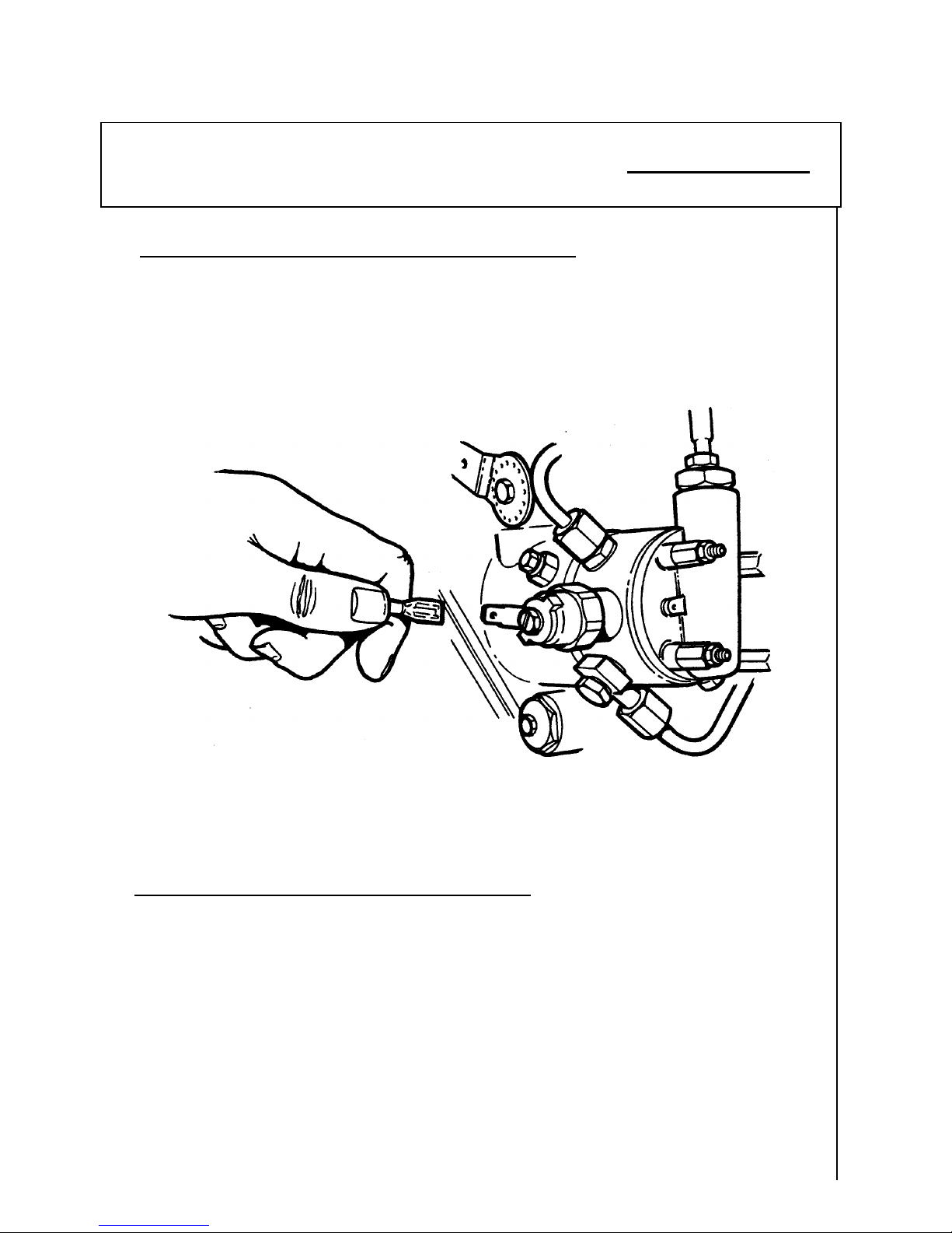
engine is run. Connect the engine starter batteries disconnect power to the
fuel solenoid valve on the injection pump Fig. 7 and crank the engine over using
the key starter switch until pressure registers on the oil pressure gauge.
Stop cranking and check the engine and gearbox for oil or water leaks. Replace
power connector.
Fig. 7
PRIMING THE ENGINE OIL SYSTEM (TYPE 90 AND/108 ENGINES)
As only a residual amount of oil is present in the oil pump filter and oil
galleries of the engine it is therefore necessary to prime the system before the
engine is run. Connect the engine starter batteries, operate the key starter
switch with the stop control out, crank the engine over until pressure registers
on the oil pressure gauge. Stop cranking and check the engine and gearbox for
oil or water leaks.
PRIMING THE ENGINE OIL SYSTEM
THOMYCWFT
Page 5
BLEEDING THE FUEL SYSTEM
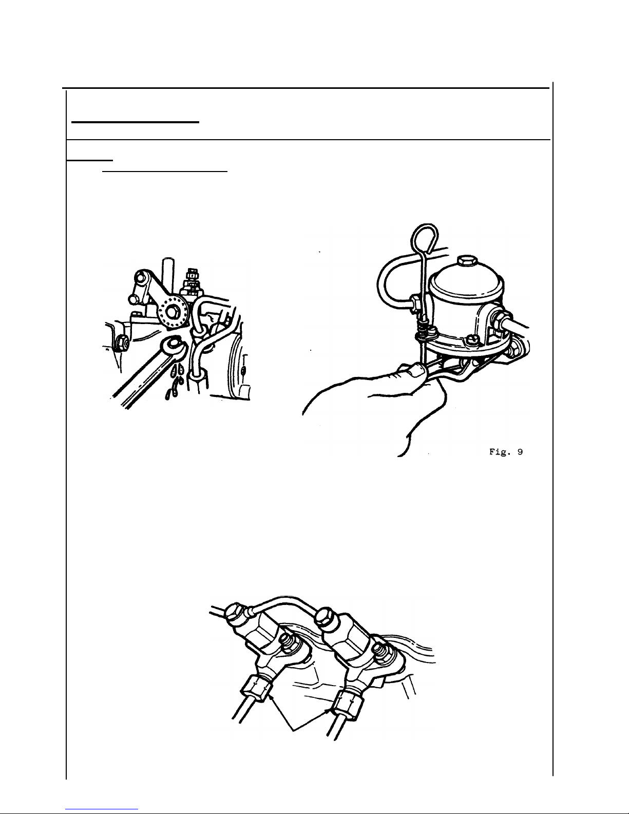
Slacken the bleed valve on the injection pump Fig. 8. Operate the lift pump
Fig. 9 and when the fuel coming from the valve is free of air bubbles, tighten the
valve.
Fig. 8
Slacken the unions at the
injector ends of any two high pressure pipes. Fig. 10. Ensure that the stop
control is in the run position and the engine speed control is in the fully
open position. Crank the engine until the fuel coming from both pipes is free from air
bubbles, then tighten the unions.
NB. After initial start procedure has been observed start the engine and allow it
to idle until it is running evenly on all four cylinders.
THORNYCROFT
BLEEDING THE FUEL SYSTEM TYPE 90 ENGINES

Fig. 10

Fig. 13
BLEEDING THE FUEL SYSTEM
5 3
Fig. 11 ~`
2 4,6
Note: After renewing the
fuel filter element it will only be necessary to bleed the fuel filter as
described in 1 and 2, provided that the engine has not been cranked while the
filter is dismantled.
1 Slacken the blanking plug in the unused outlet connection in the fuel
filter head Fig. 12. Operate the lift pump Fig. 9 (page 5) until the fuel
flowing from the plug is free of air bubbles, tighten the plug. NB. Numbers
2-6 refer to Fig. 11 bleed points.
2 Slacken the union nut at the injection pump end of the fuel feed pipe.
Operate the lift pump and when the fuel flowing from the union is free
from air bubbles, tighten the nut.
3 Slacken the air bleed screw on the injection pump body. Operate the lift pump
and, when the fuel flowing from the bleed screw is free from bubbles, tighten the screw.
4 Slacken the air bleed screw on the injection pump governor housing.
Operate the lift pump until the fuel flowing from the bleed screw is free
from air bubbles, leave the bleed screw slack.
5 Slacken the air bleed screw on the injection pump high pressure banjo bolt.
Operate the starter motor while operating the throttle control and, when the
fuel flowing from the high pressure bleed screw is free of air bubbles,
tighten the bleed screw.
6 Continue cranking the engine with the starter motor to expel any air
trapped in the governor and, when the fuel flowing from the governor
housing bleed screw is free of air bubbles, tighten the screw.
Slacken the unions at the injector ends of any two high pressure pipes. Fig.
13. Ensure that the stop control is in the run position and the engine
speed control is in the fully open position. Crank the engine until the fuel
comibng from both pipes is free from air bubbles, then tighten the unions. NB. After initial
start procedure has been observed start the engine and allow it to idle until it is
running evenly on all four cylinders.
BLEEDING THE FUEL SYSTEM TYPE 108 ENGINES
THORN
Fig. 12
 Loading...