

Page 1
Part No. 84493
5000TOC Sensor
Standard Operating Procedure
for TOC Calibration
This document contains proprietary information, which is protected by copyright. All rights are reserved. No part of this
document may be photocopied (other than where specifically noted), reproduced or translated, into another language without
the prior written consent of Mettler-Toledo Thornton, Inc.
Page 2
©Mettler-Toledo Thornton, Inc. 2007
No part of this manual may be reproduced or transmitted in any form or by any means, electronic or mechanical,
including photocopying (other than where specifically noted), for any purpose without the express written
permission of Mettler-Toledo, Inc.
U.S. Government Restricted Rights: This documentation is furnished with Restricted Rights.
METTLER TOLEDO THORNTON RESERVES THE RIGHT TO MAKE REFINEMENTS OR
CHANGES WITHOUT NOTICE.
Page 3
IMPORTANT SAFETY INFORMATION
Please read thoroughly before operating the 5000TOC System Suitability Test and TOC
Calibration Kit -
• Follow all warnings, cautions, and instructions indicated on and supplied with this product.
• Install equipment as specified in this instruction manual. Follow appropriate local and national codes.
• Use only factory documented components for repair. Tampering or unauthorized substitution of parts and procedures can
affect the performance and cause unsafe operation of your process as well as void factory warranties.
• Protective covers must be in place unless qualified personnel are performing maintenance.
• If this equipment is used in a manner not specified by the manufacturer, the protection provided by it against hazards may
be impaired.
• Prior to shipping the sensor back to the factory for repair or re-calibration, water MUST be drained from sensor to avoid
damage due to freezing.
WARNINGS:
• Installation of cable connections and servicing of this product require access to shock hazard voltage levels.
• Main power must employ a switch or circuit breaker as the disconnecting device for the equipment.
• Electrical installation must be in accordance with the National Electrical Code and/or any other applicable national or local
codes.
• Safety and performance require that this instrument be connected and properly grounded through a three-wire power
source.
This manual includes safety information with the following designations and formats:
WARNING: POTENTIAL FOR PERSONAL INJURY.
CAUTION: possible instrument damage or malfunction.
NOTE: important operating information.
Definition of Equipment Symbols
Apply power to UV lamp only when installed in housing in accordance with instruction manual.
On the instrument indicates: Warning Caution, risk of electric shock.
On the instrument indicates: Caution (refer to accompanying documents).
Warning: UV RADIATION HAZARD
DO NOT remove UV lamp from housing unless power is off.
Always protect eyes and skin from exposure to UV light
~ On the instrument indicates: There is alternating current present.
Page 4

Page 5

TABLE OF CONTENTS
1. INTRODUCTION................................................................................................................... 1
2. SCOPE ..............................................................................................................................1
3. EQUIPMENT REQUIRED........................................................................................................1
4. EQUIPMENT DATA ............................................................................................................... 1
5. FLOW RATE CALIBRATION ....................................................................................................1
5.1. Flow Rate Verification Before Calibration................................................................................... 1
5.2. Flow Rate Calibration............................................................................................................. 2
5.3. Flow Rate Verification After Calibration...................................................................................... 2
6. EQUIPMENT PREPARATION................................................................................................... 3
6.1. Installing the Thornton 5000TOC System Suitability Test and Calibration Kit Brackets..................... 3
6.2. Purge 5000TOC Sensor ......................................................................................................... 5
7. TOC CALIBRATION ...............................................................................................................5
7.1. TOC As Found....................................................................................................................... 5
7.2. TOC Calibration Procedure...................................................................................................... 5
7.3. TOC Calibration Verification Procedure .....................................................................................6
8. RESTORE TO OPERATION ..................................................................................................... 6
9. SETTING SAMPLE FLOW RATE............................................................................................... 7
9.1. Flow Rate Adjustment Procedure ............................................................................................. 7
9.2. Flow Rate Indication ...........................................................................................................
10. WORKSHEET 1: PART NUMBER AND SERIAL NUMBER DATA......................................................9
11. WORKSHEETS FOR CALIBRATION AND VERIFICATION ............................................................. 10
... 8
Page 6

Page 7

1. Introduction
The Thornton 5000TOC Total Organic Carbon Sensor and 770MAX meter measures the amount of organic carbon in high purity
waters by oxidizing organic carbon to CO
compensated conductivity measurements of the sample flow stream at points before and after oxidation is used to calculate the
amount of organic carbon present.
Throughout the test procedure, the units “ppb” or “ppb Carbon” and “µg Carbon/L” will appear. They are identical for this
procedure. “ppb” (or ppm) is the common terminology used throughout the industry, though it is not a recognized SI unit.
with appropriate UV radiation. The resulting increase between two temperature-
2
2. Scope
This document provides procedures to calibrate the Thornton 5000TOC Total Organic Carbon Sensor (PN 58 036 001 or PN
58 036 002 and related part numbers). The 5000TOC Sensor is used with the Thornton 770MAX meter. Calibration of the
770MAX meter is covered in separate documentation.
3. Equipment Required
• Thornton 5000TOC System Suitability Test and TOC Calibration Kit (Thornton PN 58 091 525).
• Thornton 5000TOC Calibration Solution Set (Thornton PN 58 091 529).
• Stop watch or other timing device with 1 second resolution.
• 100 mL or larger volumetric container such as graduated cylinder with <3% tolerance.
Note: Use a hold time to freeze the relay and analog outputs so that alarms are not triggered during any service procedures.
Normal relay and analog output operation resumes when the set period has elapsed or when the hold time is reset to zero. Set
hold time by pressing “Menu” from the 770MAX main display. Scroll to “Set Hold time” by using the up/down arrows. Press
“Enter”, then enter a time between 1 to 99 minutes, and press “Menu”. The hold time is now set.
Caution: Be sure to adjust needle valve to less than 3 turns from closed position before re-installing into process line.
4. Equipment Data
Record all relevant data identified in Worksheet 1, Section 10.
5. Flow Rate Calibration
This procedure uses a “volume and time” method for calibrating the flow sensor. Process water is sufficient to use for this
calibration. The end of the drain tube at the sample outlet is the measurement point.
NOTE: Since it is possible for the person performing this calibration to come into contact with the process water, use of
protective gloves, or other suitable safety equipment is recommended.
Warning: If the process water is hot, protection from direct contact should be used, or an alternate source of water must be
provided.
5.1. Flow Rate Verification Before Calibration
1. Adjust the 5000TOC flow rate to 20 ± 1 mL/min as described in Section 9, Setting Sample Flow Rate.
2. Arrange the drain tube at the atmospheric drain such that the water dripping from it may be collected into the
volumetric container.
3. On the 770MAX, press Menu (exit).
Page 1
Page 8

4. Press S or T to select Calibrate. Press Enter (or Page Down).
5. Press S or T to select Sensor. Press Enter (or Page Down).
6. Enter Output Hold Time. Press Enter (or Page Down). “Output Hold Time” is the amount of time that you
want the present relay status and analog output value to be held (unchanged) while calibration is performed.
7. Press S or T to select the letter for the measurement of the 5000TOC Sensor being calibrated. Any of the
various sub-sensors within the 5000TOC Sensor may be calibrated from any other measurement letter. For
example, if Measurement C is the TOC from the unit being calibrated, and Measurement D is its conductivity,
then any of the sub-sensors within the unit may be calibrated from either Measurement C or D. Press Enter.
8. Press S or T to select 2-point. Press Enter or X.
9. Press S or T to select the Flow. Press Page Down. The 770MAX should now be displaying the 5000TOC
Sensor flow rate.
10. Place a dry volumetric container under the drain line to capture the water, and begin the time measurement
using the stop watch. It is important that the water collection and time start be closely matched.
11. Collect a known volume of water with the volumetric container for a specific time, at least 3 minutes.
12. Record in Table 1 Section A the volume of water in mL and the elapsed time in seconds. These two values
determine the reference flow rate.
13. Calculate the reference flow rate and record as F
in Table 1 Section A according to the equation below. The
ref
volume may also be determined by weight. Measure the mass increase of the container in grams, and divide
the mass by the density of the water (typically, 1.00 g/mL at room temperature).
==
F(mL/min)RateFlow
ref
×
(sec)TimeElapsed
14. Record the flow rate as shown on the display of the 770MAX as the F
15. Subtract the measured flow rate from the reference flow rate (F
ref
– F
(mL)collectedvolumesec/min60
eq 1
value in Table 1 Section A.
before
).
before
16. If the absolute value of the difference is less than the limit, then flow rate adjustment is not required. Press
Menu to exit and proceed to Section 6. Equipment Preparation. Otherwise, leave the 770MAX in its current
state and proceed to the next section.
5.2. Flow Rate Calibration
NOTE: All flow adjustments are to be made using the needle valve on the inlet of the 5000TOC Sensor.
1. Using the display on the 770MAX (in the calibration mode as described in Section 5.1), adjust the flow rate
through the 5000TOC Sensor to about 24 ± 1 mL/min as indicated on the 770MAX display.
2. Place a dry volumetric container under the drain line to capture the water, and begin the time measurement
using the stop watch. It is important that the water collection and time start be closely matched.
3. Collect a known volume of water with the volumetric container for a specific time, at least 3 minutes.
4. Record in Table 1 Section B the volume of water in mL and the elapsed time in seconds.
5. Using eq 1, calculate the water flow rate and record as F
6. Enter the reference flow rate into the 770MAX and press Page-Down.
7. Wait while the calibration is being performed.
8. Adjust the flow rate to about 16 ± 1 mL/min.
9. Empty the volumetric container. Repeat steps 2-7.
10. Record data as F
in Table 1 Section B.
ref2
11. After the flow sensor calibration is completed, enter the correct date. Press Page-Down.
12. Select YES to save the new calibration data within the 5000TOC Sensor.
Note: if NO is selected, the data will only be temporarily saved, and will revert back to the previous value should
power be lost or the 5000TOC Sensor patch cable is unplugged.
in Table 1 Section B.
ref1
5.3. Flow Rate Verification After Calibration
1. Repeat steps 1-11 in Section 5.1 to verify the flow sensor is in calibration.
Page 2
Page 9
2. Record the volume of water in mL and the elapsed time in seconds in Table 1 Section C. These two values determine
the reference flow rate.
3. Using eq1, calculate the reference flow rate and record in Table 1 Section C as F
4. Record the flow rate as shown on the display of the 770MAX as F
5. Subtract reference flow rate from the after flow rate (F
ref
– F
after
).
in Table 1 Section C.
after
.
ref
6. If the absolute value of the difference is less than the limit, then flow rate calibration is complete. Otherwise, return to
Section 5.2..
Flow Calibration is complete.
6. Equipment Preparation
6.1. Installing the Thornton 5000TOC System Suitability Test and Calibration Kit Brackets
The System Suitability Test and TOC Calibration Kit 58 091 525 provides the apparatus needed to perform a TOC calibration
test on the 5000TOC sensor (models 58036001 and 58036002). Components included in this kit include a bracket
assembly, transfer cap assembly, assorted fittings, 30cc plastic syringe, positive displacement pump and universal power
supply. The kit is designed for use with Thornton Standard Solution bottles included in the Calibration Solutions Kit (p/n 58 091
529).
Bracket Assembly and Pump Installation
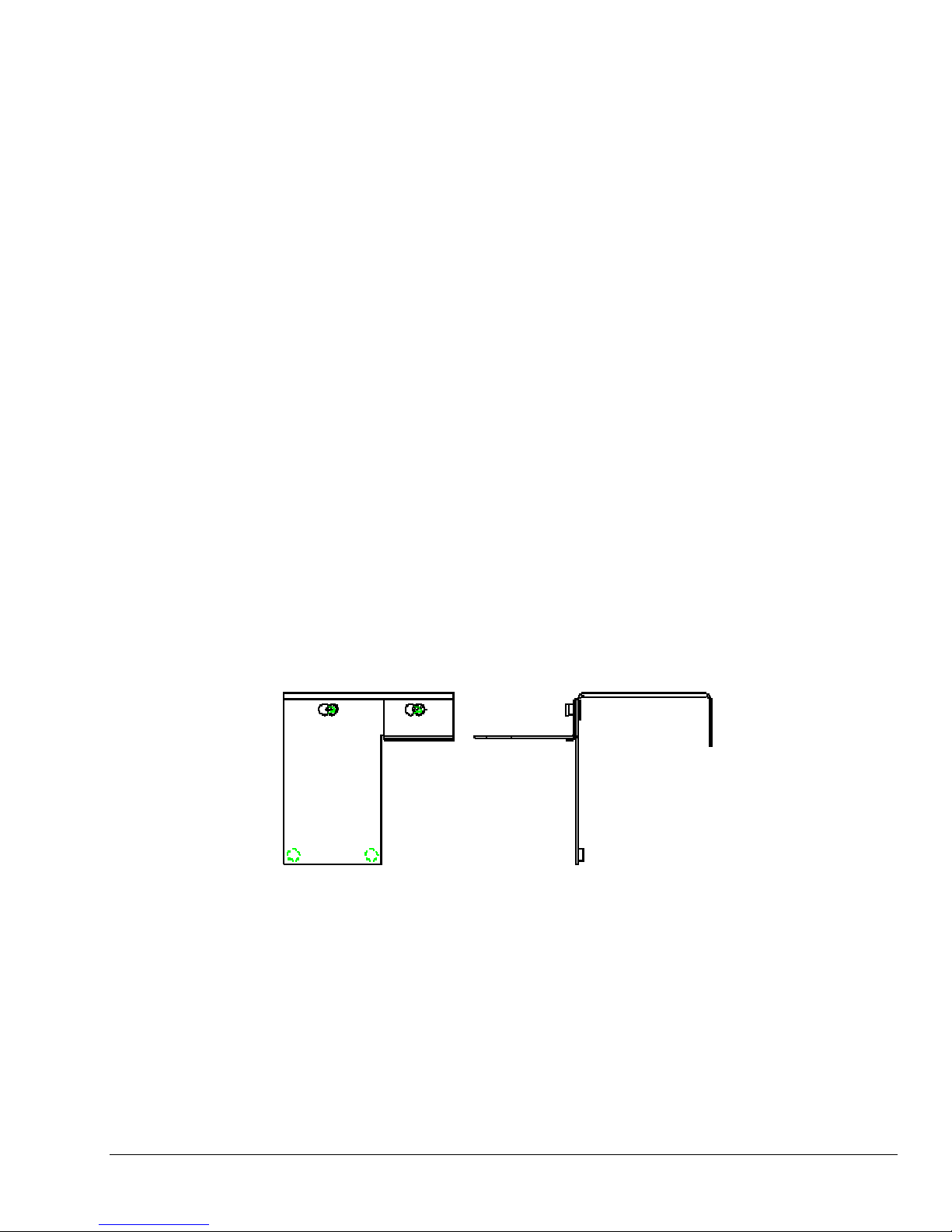
1. Remove the three individual brackets from the aluminum carrying case.
2. Attach the flat front cover bracket to the U-shaped top bracket, aligning the front cover bracket holes with the studs
located on the top bracket.
3. Do not tighten thumb screws at this time.
4. Attach L-shaped bottle bracket to the stud located on the right. Place the bottle bracket over the thumb screw and slide
it to the left, so that the smaller diameter slot is under the thumb screw. Hold the bracket and tighten the thumb screw
to secure the bottle bracket. Figure 1 shows proper orientation of all three bracket components.
Figure 1. Bracket assembly
5. Remove the pump assembly from the aluminum carrying case.
6. Attach the pump assembly (with integral bracket) to the left stud, aligning the large diameter hole in the pump bracket
over the thumb screw. Place the pump assembly bracket over the thumb screw and slide it to the left, so that the
smaller diameter slot is under the thumb screw. Tighten to secure the pump. The pump should lay flat on the front
cover bracket.
7. Install tube fittings onto the threaded connections, labeled ‘Inlet’ and ‘Outlet’, on the top side of the pump. Pump inlet
and outlet tubing should only be installed when starting a TOC calibration. This will eliminate the possibility of
contaminating tubing and fittings.
Page 3
Page 10
TOC Calibration Apparatus Installation
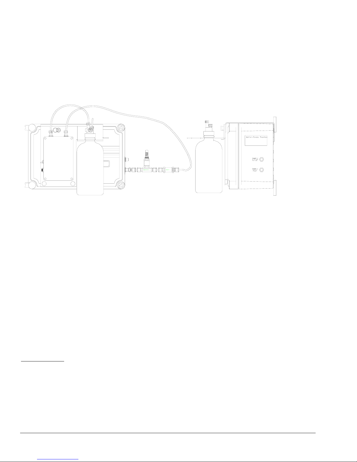
1. Carefully place the assembled bracket, with pump, over the 5000TOC sensor. Slide the assembly to the left
slightly, leaving the ‘UV Lamp On’ key accessible. Figure 2 shows proper location and orientation of the TOC
Calibration Apparatus.
OC
Figure 2. TOC Calibration Apparatus
(shown with solution bottle installed)
2. Verify the pump switch is in the off position.
3. Connect the Universal Power Supply to the pump and to 100–240 VAC 50-60 Hz power. The kit includes a North
American AC power cord. Replace or adapt the power cord as necessary and in accordance with local
regulations.
4. Clean the Transfer Cap and the Open Top Cap using deionized or process water (water to be tested). These parts
are identified in the parts description for the TOC Calibration Pump Kit.
5. Assemble as shown in Figure 2. Without touching the lower 7 ¾” (20 cm) of the tubing, carefully insert the bottle
tube (plain tube without nut and ferrule from 5000TOC System Suitability Test and TOC Calibration Kit) into the
thumb fitting on the Transfer Cap fitting with 6 ¼” (16 cm) extending from bottom of Transfer Cap. Do not allow
the lower end of the bottle tube to become contaminated. If the tube will not slide through the thumb fitting,
inspect the ferrule immediately below it.
6. Connect the other end of the bottle tube to the “Inlet” fitting on the pump.
7. Connect the plain end of the Sensor Tube (tube with nut and ferrule from the 5000TOC System Suitability Test and
TOC Calibration Kit) to the “Outlet” fitting on the pump.
IMPORTANT NOTE:
When the pump is first put into service, or after extended storage, it may need to be primed by injecting reagent water into the
inlet fitting with the syringe provided. Place the pump in its normal vertical position with inlet tube from the bottle removed from
the inlet fitting and the outlet tube placed to discharge into a container. Draw reagent water into the syringe, place the tip of the
30cc syringe into the pump inlet fitting, turn on the pump and push about 10 ml of water into the fitting or until water appears at
the outlet fitting. Excess water will run from the inlet fitting. Turn off the pump. Reattach the tube from the bottle to the pump
inlet fitting, and proceed.
Page 4
Page 11

6.2. Purge 5000TOC Sensor
1. Remove the seal from one of the two bottles of Blank Water supplied with the TOC Calibration Solutions Kit.
2. Place the Blank Water bottle into the holder notch on the bracket.
3. Clean the bottom of the transfer cap and the bottom of the transfer tube with de-ionized water or the process water to be
tested.
4. Remove the solid cap from the Blank Water container and install the transfer cap.
5. The end of the bottle tube should be near the bottom of the Blank Water container.
6. Turn off the process water supply to the 5000TOC Sensor using the shut off valve (recommended in the 5000TOC Sensor
Instruction Manual). Ensure the process water supply is turned of by viewing the discharge line at the atmospheric
drain.
7. Using 5/16" and 3/8" wrenches, remove the nut on the process supply tube at the inlet to the 5000TOC Sensor.
8. Hold the ferrule end of the Sensor tubing from the pump to direct its water flow away from potentially sensitive items. If
necessary, direct the spray into a suitable container.
9. Turn on the pump, allowing water to flow from the ferrule end of the Sensor tube for 10 to 20 seconds.
10. Turn off pump.
11. Connect the nut end of the Sensor tubing to the inlet of the Sensor and tighten it with the 5/16" and 3/8" wrenches.
12. Turn on the the pump. Note water dripping from the sensor discharge tubing at the atmospheric drain. Allow the sensor
to purge for at least 5-10 minutes.
13. Turn off the pump.
7. TOC Calibration
Slope calibration is performed using a solution of known TOC concentration. Mettler-Toledo Thornton provides the 5000TOC
Calibration Solution Set (P/N 58 091 529) with a bottle of 500 ppb (sucrose) calibration solution for this purpose. The kit also
contains a bottle of 250 ppb (sucrose) for verification.
7.1. TOC As Found
1. Remove the Transfer Cap from the Blank Water bottle and place it on the 500 ppb Sucrose Solution bottle.
2. Install the 500 ppb Sucrose Solution bottle on the Bottle Holder bracket.
3. Turn on the pump. Water should now be visible at the drain line at the atmospheric drain. Note: the 500 mL volume of
the calibration solution will provide more than 20 minutes of operation at the nominal flow rate of 20 mL/min.
4. Adjust the flow rate to 20 mL/min per Section 9, Setting Sample Flow Rate.
5. Verify that the UV Lamp is on. The lamp must be illuminated to measure and display TOC.
6. Allow the 500 ppb solution to flow through the 5000TOC sensor until the readings stabilize, approximately 5 minutes.
7. Record the TOC of the Reference Solution into Table 2, TOC
8. Record the TOC of the 5000TOC Sensor into Table 2, TOC
9. Compute the difference, TOC
- TOC
ref
before
.
10. If the absolute value of the difference is less than the limit, then a TOC calibration is not required. Turn off the pump and
proceed to Section 8. Restore to Operation.
11. If TOC calibration is required, proceed to Section 7.2., TOC Calibration Procedure.
7.2. TOC Calibration Procedure
1. If the TOC calibration requires adjustment, enter the TOC of the Reference Solution into the 770MAX. This value should
be entered as soon as practical after reading the Reference Sensor.
2. Press Menu (exit) to go to MAIN MENU.
3. Press S or T to select Calibrate. Press Enter (or Page Down).
4. Press S or T to select Sensor. Press Enter (or Page Down).
ref
before
.
.
Page 5
Page 12

5. Enter Output Hold Time. Press Enter (or Page Down).
6. Press S or T to select the letter for the measurement of the 5000TOC Sensor being calibrated. Press Enter.
7. Press S or T to select 1-point. Press Enter or X.
8. Press S or T to select TOC. Press Page Down.
9. Press S or T to select Slope. Press Page Down.
10. Enter the TOC of the Reference Solution into the 770MAX.
11. Press page down.
12. Wait for calibration to complete.
13. Enter the correct date (if needed). Press Page Down.
14. Select YES to save the new calibration data within the 5000TOC Sensor. Press Enter. Note: if NO is selected,
the data will only be temporarily saved, and will revert back to the previous value should power be lost, or the
5000TOC Sensor patch cable is unplugged.
15. Return the 770MAX to measurement mode by pressing the Menu (exit) key.
16. Record the TOC
, TOC
ref
in Table 3.
after
17. Verify that the difference is within limits.
18. If the difference is acceptable; proceed to Section 7.3 TOC Calibration Verification Procedure.
19. If the difference is not within acceptable limits, repeat Section 7.2., TOC Calibration Procedure.
7.3. TOC Calibration Verification Procedure
1. Turn off the pump.
2. Remove the transfer cap from the Reference Solution, install the 250 ppb Sucrose Solution bottle on the bracket,
and attach the Transfer Cap to the new solution.
3. Turn on the pump.
4. Verify the flow is 20 mL/min.
5. Wait until the displayed reading stabilizes, typically 5 minutes.
6. Record the TOC of the Reference 250 ppb solution in Table 3.
7. Record the measured TOC displayed on the 770MAX in Table 3.
8. Verify that the system response matches the TOC concentration listed on the container within the limits stated in
Table 3.
9. If the limits are not acceptable, repeat sections 7.2 and 7.3.
10. If the limits are acceptable, the procedure is complete. Turn off the pump and proceed to Section 8,
TOC Calibration is complete.
8. Restore to Operation
Caution: Be sure to adjust the inlet needle valve to less than 3 turns from closed position before re-installing into the
process line.
1. Restore the connections to the unit in the same operational configuration prior to calibration.
2. Remove the System Suitability Test and TOC Calibration Kit.
3. Connect the process water line to the 5000TOC Sensor sample inlet.
4. Turn on the process water supply to the 5000TOC Sensor using the shut off valve (recommended in the
5000TOC Sensor Instruction Manual). Ensure the process water supply is turned on by viewing the discharge
line at the atmospheric drain.
5. Turn on the UV Lamp if not already on.
6. Adjust the flow rate to 20 ml/min per section 9, Setting Sample Flow Rate.
Page 6
Page 13
9. Setting Sample Flow Rate
At various times during the calibration of TOC the flow rate needs to be set using this procedure.
9.1. Flow Rate Adjustment Procedure
1. Press Menu (exit) to go to MAIN MENU.
2. Scroll to the Measurements menu and press Enter.
3. Select the measurement letter (A, B, C…) for the TOC measurement of interest.
4. Press Page Down (twice) until the “Push 5 for TOC menu” appears.
5. Press enter to activate Set Flow Rate option. Change this setting to Yes. This immediately initiates the Set Flow Rate
mode at the sensor. It will stay in this mode until the user changes the “Set Flow Rate: Y
If the user does not set the flow rate once the Set Flow Rate mode has been initiated, the 770MAX will time out, at which
time the mode automatically goes back to “Set Flow Rate: N
screen.
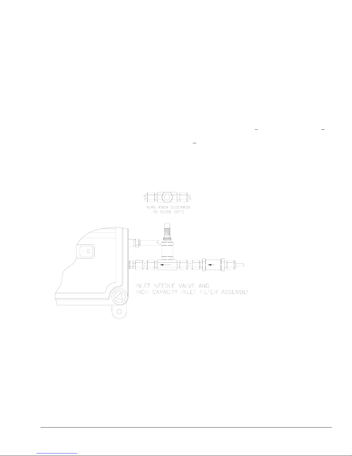
6. The flow rate is set by adjusting the inlet needle valve installed on the sample inlet connection of the 5000TOC Sensor
(see Figure 3).
NOTE: Turn the inlet needle valve adjustment knob clockwise to decrease flow and counterclockwise to increase flow.
o” and the instrument returns to the measurement display
es” back to “Set Flow Rate: No”.
7. In this mode, the LEDs on the front cover of the 5000TOC Sensor act as a bar-graph indicator as described according to
Section 9.2., Flow Rate Indication and Figure 4.
8. Adjust the inlet needle valve adjustment knob until all four LEDs light on the 770MAX.
9. Go to the 770MAX and change “Set Flow Rate: Yes” to “Set Flow Rate: No”. The flow rate setting operation is now
complete.
Figure 3. Needle Valve Location
Page 7
Page 14
9.2. Flow Rate Indication
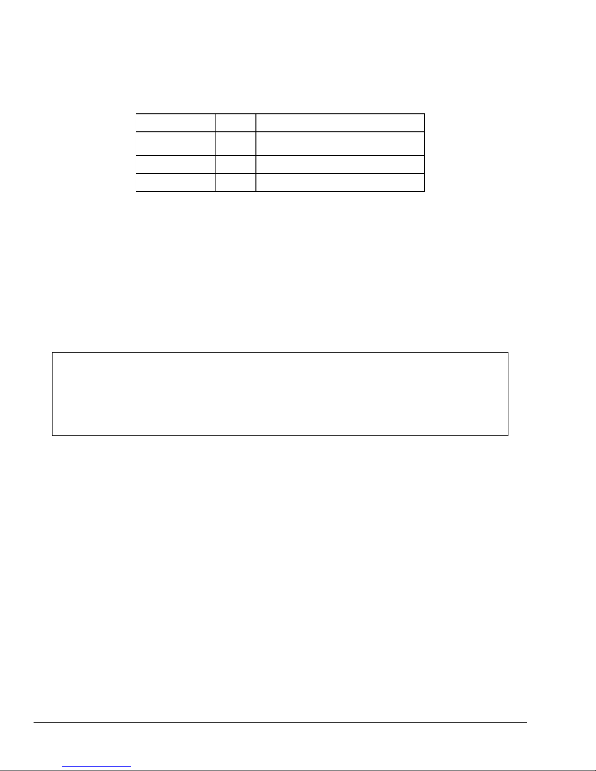
The flow rate value is indicated by the four LEDs (lights) on the front of the 5000TOC Sensor.
Fault
Error
Sensor Status
UV Lamp On
When the flow rate is at 20 mL/min (±2.5%), all four LEDs will be on.
If the flow rate is too high, the top LEDs will be on. Turn the adjustment knob clockwise.
If the flow rate is too low, the bottom LEDs will be on. Turn the adjustment knob counterclockwise.
If the flow rate is far from 20 mL/min, only the top (Fault) LED or the bottom (UV Lamp) LED will be on.
As the flow rate approaches the correct value, more LEDs will turn on. For example, if the flow rate is too high, as the
adjustment knob is turned clockwise, first the Fault LED will be on, then the Fault and Error LEDs will be on, then the
Fault, Error and Sensor Status LEDs will be on and finally all four LEDs will be on when the flow rate is 20 mL/min.
Very LOW LOW NEAR SET SET NEAR SET HIGH Very HIGH
Fault
Error
Sensor Status
UV Lamp On
The flow rate is set properly when all
LEDs are illuminated.
= LED illuminated
= LED not illuminated
= LED illuminated
= LED not illuminated
Figure 4. LED Indicator for Flow rate
Page 8
Page 15
10. Worksheet 1: Part Number and Serial Number Data
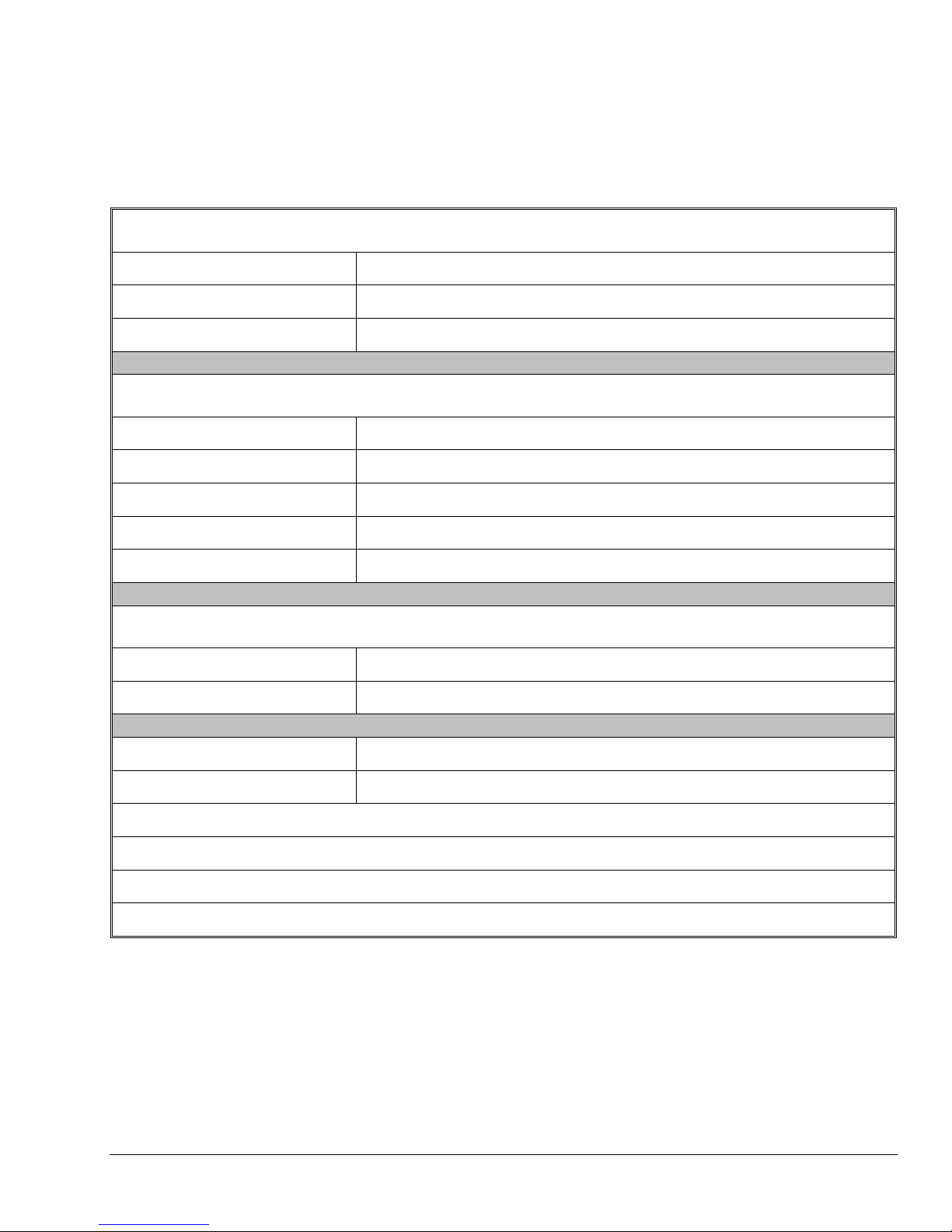
Use the table below to record part number, serial number, of the Unit Under Test (UUT) and Reference equipment. Write N/A (not
applicable) in spaces not used.
5000TOC Sensor Unit Under Test (UUT) Data
Part Number
Serial Number
ID Tag (if available)
770MAX Meter Reference Data
Part Number
Serial Number
ID Tag (if available)
Date Last Calibrated
Calibrated Due Date
Reference TOC Solution Lot Numbers
500 ppb TOC Solution
250 ppb TOC Solution
Signature
Date
Comments
Page 9
Page 16
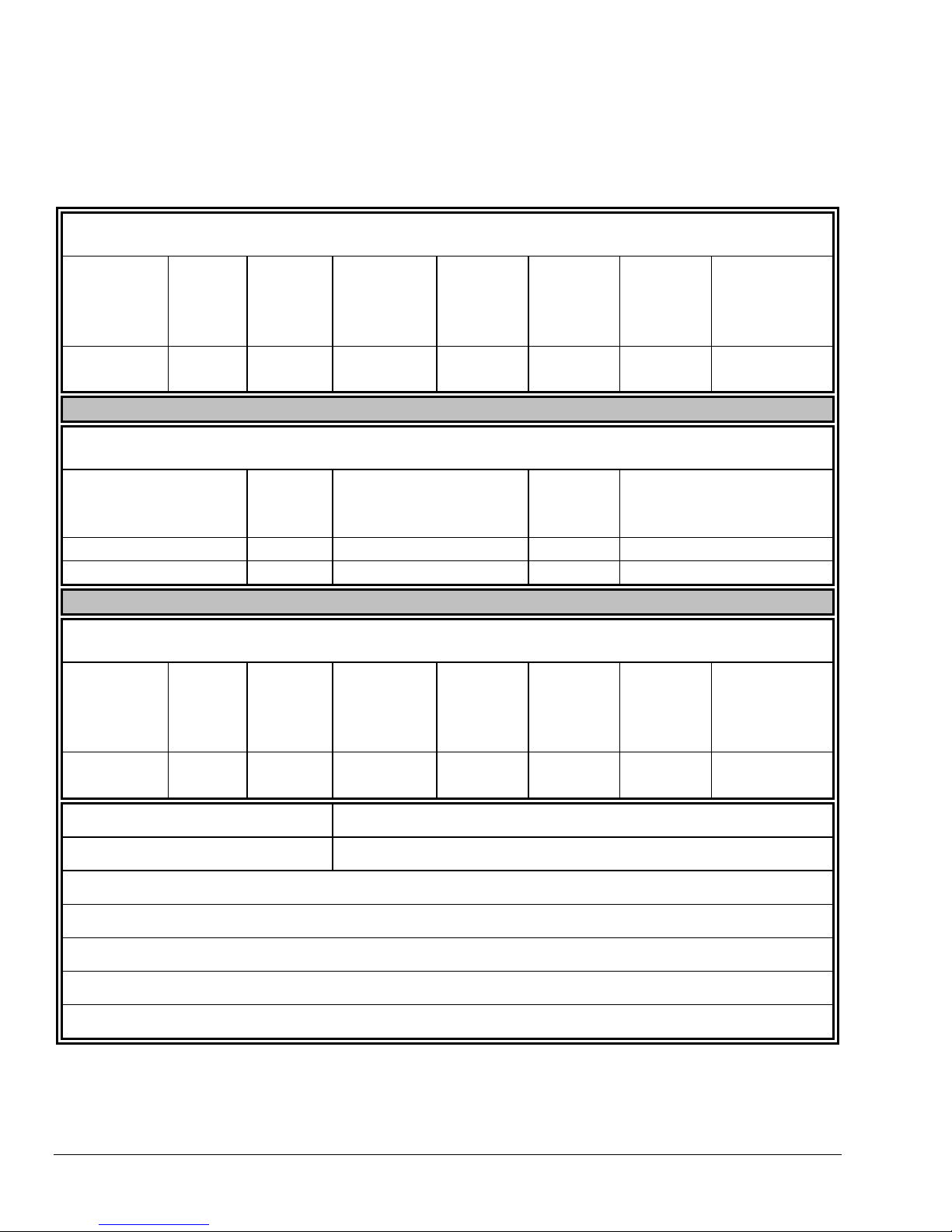
11. Worksheets for Calibration and Verification
Table 1. Flow Sensor Verification and Calibration
Section A: Flow Sensor Verification Before Calibration
Calibration
point and
conditions
Volume
(mL)
Elapsed
Time
(sec)
Reference
Flow Rate
F
ref
(mL/min)
As Found
Flow Rate
F
before
(mL/min)
F
- F
ref
(mL/min)
As found ~20
mL/min
Section B: Flow Sensor Calibration
Calibration
point and
conditions
Volume
(mL)
#1 ~24 mL/min F
#2 ~16 mL/min
Elapsed
Time
(sec)
ref1
F
ref2
Section C: Flow Sensor Verification After Calibration
Calibration
point and
conditions
After ~20
Reference
Volume
(mL)
Elapsed
Time
(sec)
Flow Rate
F
ref
(mL/min)
After
Flow Rate
F
after
(mL/min)
F
- F
ref
(mL/min)
mL/min
Within Limits
or
before
Limit
(mL/min)
±1
Adjustment
Required
Reference
Flow Rate
(mL/min)
Within Limits
or
after
Limit
(mL/min)
±1
Adjustment
Required
Signature
Date
Comments
Page 10
Page 17
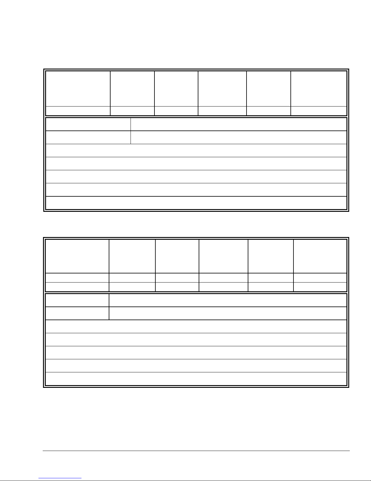
Table 2. TOC As Found Verification
Reference
TOC
ref
(ppb)
TOC, 500 ppb ±50
Signature
Date
Comments
As Found
TOC
before
(ppb)
TOC
- TOC
ref
(ppb)
before
Limit
(ppb)
Within Limits
or
Adjustment
Required
Table 3. TOC Calibration and Verification
Reference
TOC
ref
(ppb)
TOC, 500 ppb ±50
TOC, 250 ppb ±25
Signature
Date
Comments
As Measured
TOC
after
(ppb)
TOC
– TOC
ref
(ppb)
after
Limit(ppb)
Within Limit?
(ppb)
Page 11
Page 18

This page is intentionally blank.
Page 12
Page 19

Page 20

Mettler-Toledo Thornton, Inc.
36 Middlesex Turnpike
Bedford, MA 01730
Tel. +1-781-301-8600
Fax +1-781-271-0214
Toll Free +1-800-510-PURE
[email protected]
Part 84493
Rev.A 01/07
www.mt.com/thornton
 Loading...