

Thorn security TYCO T1216W-C Installation And Commissioning Manual

EQUIPMENT: T1216W-C
PUBLICATION: MARINEW-P-I
ISSUE No. & DATE: 1 11/12
© 2012 Thorn Security Ltd PAGE 1 of 39
Registered Company: Thorn Security Ltd. Registered Office: Dunhams Lane Letchworth Garden City Hertfordshire SG6 1BE
TYCO T1216W-C
Marine Fire Detection/Alarm Control Panel and Repeater
Installation and Commissioning Manual

T1216W-C
MARINEW-P-I
1 11/12
PAGE 2 of 39
List of Contents
1. LIST OF FIGURES ................................................... 3
2. LIST OF TABLES .................................................... 3
3. INTRODUCTION ...................................................... 4
4. INSTALLATION AND COMMISSIONING OVERVIEW ..... 4
5. INSTALLATION ....................................................... 4
5.1 ELECTRICAL SAFETY ...................................... 4
5.2 INSTALLATION INSTRUCTIONS ......................... 6
5.2.1 T1216W PANEL INSTALLATION
INSTRUCTIONS ........................................ 6
5.2.2 CONNECTION OF THE INCOMING AC
POWER SUPPLY ...................................... 8
5.2.3 T1200B-C BATTERY BOX INSTALLATION .. 8
5.2.4 BATTERY INSTALLATION .......................... 8
5.2.5 BATTERY CONNECTION ........................... 8
5.2.5.1 CONNECTING THE BATTERY BOX TO THE
PANEL PSU 9
5.2.6 INSTALLATION AND CONNECTION OF THE
C1631 REPEATER INTERFACE ................. 9
5.2.7 INSTALLATION AND CONNECTION OF THE
C1665 MUSTER INTERFACE .................... 9
5.3 MODIFICATIONS TO THE WATER MIST RELAY
CONTROL PANEL ......................................... 12
5.3.1 MODIFICATION 1 [SYSTEM ABNORMAL]: .. 12
5.3.2 MODIFICATION 2 [SYSTEM OPERATED]: .. 12
5.3.3 MODIFICATION 3: [FAULT INPUT FROM
T1216W-C] ......................................... 13
5.4 INTERCONNECTIONS WITH THE WATER MIST
RELAY CONTROL PANEL .............................. 13
5.4.1 FINAL CONNECTIONS BETWEEN THE
T1216W AND WMRCP ........................ 13
5.5 REPLACING THE DISPLAY INSERTS ............... 14
5.5.1 TO CHANGE THE INSERTS ...................... 14
5.5.2 TO FIT THE OPTIONAL DOOR STAY ........ 16
6. COMMISSIONING .................................................. 17
6.1 INTRODUCTION ............................................ 17
6.2 COMMISSIONING CHECKLIST ........................ 17
6.3 AN OVERVIEW OF THE COMMISSIONING
PROCEDURE................................................ 17
6.4 PRE-COMMISSIONING WIRING CHECK .......... 17
6.5 POWERING UP ............................................. 18
6.6 CONFIGURATION .......................................... 19
6.6.1 BASIC DEFAULT CONFIGURATION ........... 19
6.6.2 VESSEL-SPECIFIC CONFIGURATION ....... 19
7. OPERATING THE ENGINEER’S FUNCTIONS ............. 19
7.1 ENGINEER’S ZONE/OUTPUT CONFIGURATION
PROCESS: ................................................... 19
7.2 ZONE OR OUTPUT CONFIGURATION: ............. 19
7.3 TO RESTORE THE FACTORY DEFAULT
CONFIGURATION FOR ZONES & OUTPUTS: .... 20
7.4 ENGINEER’S ZONE/OUTPUT CONFIGURATION
TIME-OUT WARNING: ................................... 20
7.5 INVALID CONFIGURATION CONDITIONS: ......... 20
7.6 LIST OF CONFIGURATION DIL SWITCHES AND
THEIR FUNCTIONS: ....................................... 21
7.7 LIST OF LINK CONFIGURATION FEATURES ...... 23
7.8 DIL SWITCH SETTINGS ON THE REPEATER
INTERFACE BOARD: ..................................... 24
7.8.1 C1630 OUTPUT INTERFACE
CONFIGURATION ................................... 24
7.8.2 C1634 8 WAY VOLT FREE RELAY OUTPUT
MODULE CONFIGURATION ...................... 24
7.9 COMMISSIONING PROCEDURE ...................... 25
7.9.1 ALARM CIRCUITS .................................. 25
7.9.2 ZONES ................................................. 25
7.9.3 CLASS CHANGE INPUT .......................... 26
7.9.4 FIRE [ROUTING] OUTPUT....................... 26
7.9.5 FAULT [ROUTING] OUTPUT .................... 26
7.9.6 FIRE PROTECTION OUTPUT ................... 26
7.9.7 ANCILLARY INPUTS................................ 26
7.9.8 ANCILLARY OUTPUTS ............................ 26
7.9.9 REPEATERS [WHEN SUPPLIED] ............... 26
7.9.10 REPEATER MUSTER LINK [IF FITTED] ...... 27
7.9.11 POWER SUPPLY UNIT. .......................... 27
7.9.12 T1216W-C – WMRCP INTERFACE. ...... 27
7.9.13 FINAL DRESSING OF THE CABLES .......... 27
8. USER INDICATIONS .............................................. 29
9. USER CONTROLS ................................................ 30
10. PCB LAYOUTS ................................................. 31
11. INSTALLATION DETAILS ..................................... 34
12. WIRING DIAGRAMS ........................................... 35
13. WIRING DIAGRAM NOTES .................................. 39

EQUIPMENT: T1216W-C
PUBLICATION: MARINEW-P-I
ISSUE No. & DATE: 1 11/12
© 2012 Thorn Security Ltd PAGE 3 of 39
Registered Company: Thorn Security Ltd. Registered Office: Dunhams Lane Letchworth Garden City Hertfordshire SG6 1BE
1. List of Figures
FIGURE 1 – BULK HEAD MOUNTING DETAILS .............. 7
FIGURE 2 – BATTERY CLAMP DETAILS ...................... 10
FIGURE 3 – REPEATER CONNECTION DIAGRAM ......... 11
FIGURE 4 – MUSTER INTERFACE WIRING DIAGRAM ... 11
FIGURE 5– SYSTEM ABNORMAL MODIFICATION ........ 12
FIGURE 6– SYSTEM OPERATED MODIFICATION ......... 12
FIGURE 7– ADDITIONAL FAULT RELAY ...................... 13
FIGURE 8 – DISPLAY INSERT REPLACEMENT ............. 15
FIGURE 9– DOOR STAY ASSEMBLY .......................... 16
FIGURE 10 – C1627 MOTHERBOARD LAYOUT .......... 31
FIGURE 11 – REAR RIGHT HAND SIDE OF DISPLAY PCB
............................................................ 32
FIGURE 12 – C1634 RELAY OUTPUT MODULE ......... 32
FIGURE 13 – C1630 OUTPUT EXPANSION INTERFACE
............................................................ 33
FIGURE 14 – C1631 REPEATER INTERFACE BOARD . 33
FIGURE 15 – C1665 MUSTER INTERFACE BOARD ..... 33
FIGURE 16 – T1216W-C INSTALLATION DRAWING.... 34
FIGURE 17 – MAINS AC CHANGE-OVER UNIT
ELECTRICAL INSTALLATION DIAGRAM ..... 35
FIGURE 18 – T1216W-C INTERNAL LAYOUT DIAGRAM
............................................................ 36
FIGURE 19 – T1216W-C MOTHERBOARD, PSU &
REPEATER WIRING DIAGRAM ................. 37
FIGURE 20 – WATERMIST PANEL WIRING DIAGRAM .. 38
2. List of Tables
TABLE 1 – CONTENT OF SPARES BAG ......................... 6
TABLE 2 – C1631 SETTINGS FOR REPEATER QUANTITY
............................................................. 24
TABLE 3 – C1631 SETTING FOR REPEATER ADDRESSES
............................................................. 24
TABLE 4 – SETTING QUANTITY AND TYPE OF O/P
MODULES ON THE C1630 ...................... 24
TABLE 5 – SETTING C1634 BOARD ADDRESS ........... 24
TABLE 6 – SETTING C1634 ZONE RANGE ................. 24
TABLE 7 – SETTING C1634 TO FIRE PROTECTION
MODE ................................................... 25
TABLE 8 – ZONE AND ZONAL OUTPUT ALLOCATION ... 25
T1216W-C
MARINEW-P-I
1 11/12
PAGE 4 of 39
3. Introduction
This manual contains all the information necessary
for the installation, commissioning and maintenance
of the T1216W panel.
NOTE: It is important to read this manual fully
before commencing installation.
The following supporting documentation is also
available:
T1216W-C Application Guide
Related Documentation:
T1200-C Sales Literature
T1200-C Panel Application Guide
T1200-C User Manual
T1200-C Log Book
T1200-C Insert Template
Mains AC Changeover Unit Fixing
Instructions.
Note: References are made throughout this
document to “Fire Protection Output” and “Fire
Output”. These refer to particular outputs from the
T1216W panel and are provided for specific
purposes:
Fire Protection Output: An output used to
activate ancillary fire protection equipment or
systems. For example, fire doors or plant
shutdown.
Fire Output: An output used to send a
common fire warning signal to a remote fire
monitoring station.
References are also made to “Manual Fire Alarm”
and “Muster”. These relate to fire alarm sounder
operating modes which are activated manually from
the fire panel display. The panel is configurable to
one or other of the two modes.
Detailed descriptions of both outputs are provided
within the following text.
4. Installation and Commissioning
Overview
This section lists the steps that are taken in
installing and commissioning a T1216W system.
Reference should be made to the T1216W
Application manual for technical details and
description of panel features.
1. Install all field wiring and equipment
Refer to the Installation instructions in section
5.2. Refer to the field device installation
manuals.
2. Install the panel
Refer to the installation instructions in section
5.2. Do not connect the field equipment at this
stage.
3. Connect any repeaters (if applicable)
Refer to the installation instructions in section
5.2.
4. Commission the panel
Refer to section 6. Commissioning.
5. Installation
The control panel must be installed by suitably
qualified technicians familiar with the installation of
fire detection and alarm systems. In addition, it is
recommended to refer to the following information:
The Current edition of the relevant wiring
regulations for ships.
Any specific vessel requirements.
Any field device installation instructions.
Any data sheet provided for the installation of
Intrinsically Safe devices.
Notes:
The rating plate, containing essential electrical
information is located on the outside of the
panel, on the left side.
The mains supply cable should be a minimum
of 1mm2 copper protected by a 5A fuse.
An appropriate lockable double pole disconnect
device shall be provided as part of the vessel
installation. This device must have a minimum
contact gap of 3mm.
5.1 Electrical Safety
WARNING:
Prior to commencing installation of the
control panel, ensure that adequate
precautions are taken to prevent
damage to the sensitive electronic components on
the display board and the control board due to
electrostatic discharge. You should discharge any
static electricity you may have accumulated by
touching a convenient earthed object. You should
repeat the process at regular intervals during the
installation process, especially if you are required to
walk over carpets.
If possible, wear an anti-static wrist strap connected
to a suitable earth point when working on the panel.
The panel must be located in an area which
complies with the environmental specification
detailed in the T1200-C Application Manual and
should be at least 2 metres away from pager
systems or any other radio transmitting
equipment. The operating temperature range of
the panel & repeater is -10ºC to +55ºC. Batteries
are housed in a separate enclosure and are
rated as operational between -20ºC to +50ºC for
charging purposes. Maximum humidity is 95%
for panel, repeater & batteries.
EQUIPMENT: T1216W-C
PUBLICATION: MARINEW-P-I
ISSUE No. & DATE: 1 11/12
© 2012 Thorn Security Ltd PAGE 5 of 39
Registered Company: Thorn Security Ltd. Registered Office: Dunhams Lane Letchworth Garden City Hertfordshire SG6 1BE
IMPORTANT NOTES ON BATTERIES:
DANGER: Batteries are electrically live
at all times, take great care never to
short circuit the battery terminals.
WARNING: Batteries are often heavy;
take great care when lifting and
transporting batteries. For weights
above 24 kilos, lifting aids should be
used.
DANGER: Do NOT attempt to remove
the battery lid or tamper with the
internal workings of the battery.
Electrolyte is a highly corrosive
substance, and presents significant danger to
yourself and to anything else it touches. In case of
accidental skin or eye contact, flush the affected
area with plenty of clean, fresh water and seek
immediate medical attention.
Valve Regulated Lead Acid (VRLA) batteries are
“low maintenance”, requiring no electrolyte topup or measurement of specific gravity.
WARNING: Only clean the battery case with a cloth
that has been soaked or dampened with distilled
water. Do not use organic solvents (such as petrol,
paint thinner, benzene or mineral spirits) or other
materials that can substantially weaken the case.
Do not use a dry cloth as this will generate static
electricity, which in turn may lead to an explosion.
WARNING: Avoid operating temperatures outside
the range of -15C/5F to +50°C/122°F for
float/standby applications.
The recommended normal operating temperature is
20°C.
HIGH TEMPERATURE will reduce battery service
life. In extreme cases this can cause Thermal
Runaway, resulting in high oxygen/hydrogen gas
production and battery swelling. Batteries are
irrecoverable from this condition and should be
replaced.
LOW TEMPERATURE will prolong battery life but
reduce output capacity.
DANGER: Do not incinerate batteries.
If placed in a fire, the batteries may
rupture, with the potential to release
hazardous gases and electrolyte.
VRLA batteries contain substances
harmful to the environment.
Exhausted batteries must be recycled.
Return them to the battery
manufacturer or take them to your
Council waste disposal site for
appropriate disposal.
ELECTRICAL SAFETY:
The volt-free relay contacts provided within the
panel must not be used to directly switch any
voltage that exceeds 30V. (Please also refer to
relay rating data).
A 9V battery is supplied fitted to the inside of the
door. This battery provides power to the buzzer in
the event of total power failure or display ribbon
disconnection. The connecting lead of this battery is
disconnected from the display board during
shipping.
1. DO NOT short circuit the battery terminals or
the connecting lead.
2. DO NOT remove this battery unless it
measures 8V or less.
3. DISCONNECT THE LEAD from the display
board BEFORE replacing the battery to avoid
accidental polarity reversal which may damage
the display circuitry.
4. ALWAYS secure the battery in the battery
holder with a Tie-wrap.
5. DO NOT use rechargeable batteries as these
will gradually discharge due to internal
resistance.
Some of the panels covered by this manual
require a 110 or 230V AC supply. Refer to the
equipment rating plate and T1200-C Application
Manual for detailed information.
All installation work should be carried out in
accordance with the recommendations of the
current edition of the IEE regulations by
suitably qualified and trained personnel.
This is an IEC Class 1 electrical
appliance and therefore must have
the chassis connected to an
electrical earth.

T1216W-C
MARINEW-P-I
1 11/12
PAGE 6 of 39
Table 1 – Content of Spares Bag
Quantity
Description
Type
1
Mains Fuse
T5AH250V 20mm
1
Battery Fuse
T8AH250V 20mm
16
End-of-Line resistors for zone circuits
10k 0.25W
4
End-of-Line resistors for alarm circuits
3k9 0.25W
3
End-of-Line resistors for monitored outputs
3k9 0.25W
2
Access Control key
Key Ref - 801
Part no 509.023.061
1
Positive battery lead
Red – 250mm
1
Negative battery lead
Black – 300mm
1
Battery coupling lead
Blue – 250mm
1
Tie wrap cable clip for securing mains lead
8
Neoprene washers for box fixing
Part no 2400174
1
Total power failure battery [PP3]
Supplied fitted
1
Alternative Button test insert
Panel - English
1 x THORN
1 x TYCO
TYCO & THORN Logo Labels
Self-Adhesive Label
1
T1200C Documentation CDROM
CDROM
5.2 Installation Instructions
1. Carefully remove the control panel from the
packing and lay the panel on a flat surface.
2. Locate the spares bag (either inside the
packing box or inside the panel) and check
that the items shown in Table 1 above are
present.
5.2.1 T1216W Panel Installation
Instructions
Note: The panel is supplied configured for bottom
cable entry. If top cable entry is required then the
door of the enclosure should be removed & fitted to
the opposite side of the enclosure. The installation
instructions below apply to top or bottom cable
entry.
1. Ensure that the panel is on a flat surface with
the door facing up.
2. Remove the panel door as follows:
3. Undo the two slotted screws that secure the
door shut. The screws will remain attached to
the door.
4. Open the door. Note that the door will open
past 180 degrees and will put tension on the
hinges if no support is provided underneath.
You may find it useful to place the packing box
underneath the door to provide support.
5. Locate the ribbon cable connecting the display
board to the main control board (motherboard).
Push the metal retaining clip off the connector
on the display and pull the ribbon cable out of
the connector.
6. Locate the earth strap connected to the door.
Pull the earth strap connector off the spade
terminal on the door.
7. Use a suitable flat blade screwdriver to
unscrew the hinges whilst supporting the door.
8. Place the door and hinge fixing screws
carefully to one side.
9. The chassis is fixed to the enclosure backbox
at five points. Three of these points are keyhole type; two are round holes for screws.
10. Remove the Chassis from the enclosure as
follows:
(a) Disconnect the chassis earth lead from
the spade terminal on the enclosure
backbox.
(b) Remove the two cross-head screws at the
bottom left & right corners of the chassis
(towards the gland plate).
(c) The three key-hole fixings do not have
screws.
(d) Slide the chassis free of the key-hole
slots.
(e) Lift the chassis out of the enclosure and
place carefully to one side. Note that the
chassis is heavy and caution should be
taken when lifting the chassis.
(f) Observe that there is a key-hole fixing in
the centre of the chassis which slides onto
a post. Care should be taken when
replacing the chassis that this key-hole
slides onto the post correctly.
NOTE: The door and chassis both contain
Control Boards with sensitive and fragile

EQUIPMENT: T1216W-C
PUBLICATION: MARINEW-P-I
ISSUE No. & DATE: 1 11/12
© 2012 Thorn Security Ltd PAGE 7 of 39
Registered Company: Thorn Security Ltd. Registered Office: Dunhams Lane Letchworth Garden City Hertfordshire SG6 1BE
electronic components on them. You must place
these items in a location where they will not be
damaged. Use the packing box to place these
items inside, ensuring that the door & chassis
remain separated. Store them in a safe place
which is clean, dry and dust-free.
Note: Do not allow the door & chassis to
come into contact with the packing foam as
this may hold a static charge.
11. Locate the earth lead connecting the gland
plate to the earth bar. Disconnect the earth
lead from the earth bar.
12. Remove the screws securing the gland plate to
the enclosure. Remove the gland plate.
13. Use a centre punch and hammer to remove
the required knock-outs by placing the centre
punch diagonally opposite the fixing point on
the knockout and striking the centre punch with
the hammer. DO NOT remove the knock-outs
from any unused cable entries.
14. Refit the gland plate ensuring that the seal is
correctly seated.
15. Re-connect the earth lead from the gland plate
to the earth bar.
For Bulk Head mounting:
(a) Identify the four indented holes in the
back of the enclosure that are used to
mount the enclosure.
(b) Mark the location of one of the upper
fixing holes on the wall/bulkhead. Drill and
fix with a suitably plated or stainless steel
M5 nut, bolt and washers (fixings not
supplied). The fixing must be sealed using
two neoprene washers [supplied with the
panel fixing kit], one fitted between the
panel and the bulkhead and the other
fitted between the panel and the steel
washer inside the panel. See Figure 1 –
Bulk Head Mounting Details. Do not fully
tighten at this stage.
(c) Level the panel and fix the remaining
fixing points as above.
(d) Check that neoprene seals have been
fitted as shown in Figure 1 then fully
tighten all of the fixing nuts & bolts.
(e) Check that the enclosure is firmly seated
against the bulk head and is not deformed
in any way.
M5 STAINLESS STEEL BOLT
M5 STAINLESS STEEL WASHER
NEOPRENE WASHER
ENCLOSURE
NEOPRENE WASHER
BULKHEAD
M5 STAINLESS STEEL WASHER
M5 STAINLESS STEEL NUT
Figure 1 – Bulk Head Mounting Details
For Console mounting:
(a) Cut a suitable hole in the console to fit the
enclosure. Dimensions are shown in
section 11.
(b) Identify the four holes in the outer flange
of the enclosure that are used to mount
the enclosure in a console.
(c) Insert the enclosure into the console. Note
that the flange will not sit flush with the
console at this stage because of the four
bushes used for securing the door.
(d) Mark the centre positions of the four
bushes. Remove the enclosure and drill
suitable sized holes to accommodate the
bushes (13mm to 15mm diameter).
(e) Insert the enclosure into the console and
check that the flange now sits flush with
the console. Drill suitable mounting holes
in the console & fix with M5 counter sunk
screws.
16. Bring all field wiring into the enclosure through
suitable cable glands, ensuring that the cable
conductors are of sufficient length inside the
enclosure (at least 30cm). Waterproof glands
and seals should be used to maintain ingress
protection against water. Ensure that all
conductors are clearly labelled. Any unused
cable entries which are open must have
waterproof knockout seals fitted.
17. Connect the earth drain wires of the field
cabling to the earth bar(s) positioned at the
back of the back-box. Up to two drain wires
may be connected to each terminal.
18. Ensure that the electrical continuity of any
cable shield is maintained through to the last
device on the circuit. The shield must only be
connected to enclosure earth in the panel by
using the earth bars provided.
19. Clear any dust and debris from inside the
enclosure.
20. Reinstallation of the chassis is the reverse of
removal. Ensure that all keyholes on the

T1216W-C
MARINEW-P-I
1 11/12
PAGE 8 of 39
chassis are fully mounted onto the posts in the
back-box.
21. Reconnect all earth wires and ensure none are
trapped between the chassis and back-box. Do
not connect the field wiring at this stage.
22. Refit the door. The refitting procedure is the
reverse of removal. Ensure that the earth strap
and ribbon cable are reconnected correctly.
23. If a door stay is supplied then this should now
be fitted following the instructions in section
5.5.2.
24. Connect the incoming protective earth
conductor to the Earth terminal in the mains
terminal block. This is the primary earth point
and is labelled [Also labelled E]; see
section 12. Wiring Diagrams.
25. NOTE: When shutting the door of the panel,
DO NOT over tighten the thumb-screws.
Tighten until finger-tight and then turn another
quarter-turn using a screwdriver.
5.2.2 Connection of the incoming AC
Power Supply
Note: For installations requiring the Mains AC
switch-over unit, a 24Vdc supply will need to be
connected from the panel to the AC mains switchover unit to drive the LED indications. See Figure
17 for wiring details.
1. With both poles of the incoming power supply
safely isolated at the feeder end, connect the
Live [AC] conductor to the mains terminal
block [L terminal] as shown in section 12.
Wiring Diagrams.
2. Connect the Neutral [AC] conductor to the
mains terminal block [N terminal] as shown in
section 12. Wiring Diagrams.
3. Secure the incoming supply cable using the
cable tie supplied. NOTE: The cable tie should
be over the outer cable insulation.
5.2.3 T1200B-C Battery Box Installation
The T1200B-C battery box can only be bulk head
mounted. The incoming cable must have an in-line
fuse in the positive power supply (fuse type: T6.3A
HRC). The fuse must be mounted external to the
battery box, in a suitable terminal box which is
close-coupled to the battery box. See Figure 19 for
wiring details.
To mount the T1200B-C battery box:
(a) Identify the three indented holes in the back
of the enclosure that are used to mount the
enclosure.
(b) Mark the location of one of the upper fixing
holes on the wall/bulkhead. Drill and fix with
a suitably plated or stainless steel M5 nut,
bolt and washers (fixings not supplied). The
fixing must be sealed using two neoprene
washers [supplied with the fixing kit], one
fitted between the panel and the bulkhead
and the other fitted between the panel and
the steel washer inside the panel. See Figure
1 – Bulk Head Mounting Details. Do not fully
tighten at this stage.
(c) Level the enclosure and fix the remaining
fixing points as above.
(d) Check that neoprene seals have been fitted
as shown in Figure 1 then fully tighten all of
the fixing nuts & bolts.
(e) Check that the enclosure is firmly seated
against the bulk head and is not deformed in
any way.
(f) Mount the fused terminal box (not supplied)
adjacent to the battery box and fit a suitable
waterproof coupling to allow cable entry from
the terminal box to the battery box.
5.2.4 Battery Installation
The T1200B-C battery box will only hold 2 x 17Ah
PowerSonic SLA batteries.
1. Remove the battery clamps from the battery
box before fitting the batteries.
2. Place the left-hand battery into the battery box.
The battery should be located toward the left
side of the enclosure, the battery terminals
should be positioned towards the front.
3. Place the right-hand battery into the battery
box. The battery should be located toward the
right side of the enclosure, the battery
terminals should be positioned towards the
front.
4. Fix the battery retaining clamps. [See Figure 2]
5.2.5 Battery Connection
1. Connect the black battery lead to the terminal
marked BAT-, connect the red battery lead to
the terminal marked BAT+.
2. The Thermistor assembly is supplied loose in
the fixing kit supplied with the T1216W-C
panel. Connect the Thermistor leads to the
terminals marked THERM.
3. Tie-wrap the Thermistor to one of the battery
leads so that when the battery leads are
connected, the Thermistor is located just
above one of the batteries.
4. The blue lead is used to connect the batteries
together. Do not connect this lead until you are
ready to power up the panel.

EQUIPMENT: T1216W-C
PUBLICATION: MARINEW-P-I
ISSUE No. & DATE: 1 11/12
© 2012 Thorn Security Ltd PAGE 9 of 39
Registered Company: Thorn Security Ltd. Registered Office: Dunhams Lane Letchworth Garden City Hertfordshire SG6 1BE
5.2.5.1 Connecting the battery box to
the panel PSU
1. Run a suitable 4-core shielded cable between
the panel and the battery box.
2. Label each core appropriately (BAT+, BAT-,
THERM, THERM).
3. Connect the negative battery conductor to the
“Batt -” [battery negative] terminal and connect
the positive battery conductor to the “Batt +”
[battery positive] terminal. Both terminals are
situated on the panel chassis.
4. Connect the Thermistor leads to the two
terminals marked “Therm” on the panel chassis.
5. Warning: Do not connect the leads to the battery
at this stage. Connection of the batteries will
power up the panel even if the mains supply is
off.
5.2.6 Installation and connection of
the C1631 Repeater Interface
Warning: Observe anti-static precautions
The C1631 interface board is not provided as
standard with the panel. It is included in the spares
kit of the repeater panel, to be fitted in the main fire
alarm panel when required.
1. Ensure that the panel and repeaters are
powered down and the main and standby
supplies are disconnected.
2. On the fire alarm panel remove the jumper link
at J22 (adjacent to J9) and fit a C1631
repeater interface to connectors J13 and J9 on
the right-hand side of the C1627 motherboard.
The board should be held in place by the
12mm high plastic spacer provided. See
Figure 10.
3. The Repeater is supplied with the C1631
Interface Board fitted.
4. Connect the RS485 data cable as shown in
Figure 3.
5. Connect the Aux 24Vdc supply from the panel
to the repeater. You can use two cores in the
data cable for this purpose only if the voltage
drop between the panel and repeater is not
more than 2Vdc.
Notes:
One repeater will draw up to 75mA which means
that the total resistance of the cable should not
exceed 24 Ohms (12 Ohms in each core). The
T1216W-C Application Guide lists cable types with
their nominal DC resistance.
If more than one repeater is required or the cable
resistance is too great, then data cable is
unsuitable for supplying power and a separate
suitable 2-core cable must be used.
Use only Plenum rated screened data cable with at
least three core-pairs to accommodate repeater
communication & Muster Interface options. 4 pairs
will be required if power is also being provided
(subject to the limitations described above).
Connect the cable screen to earth at the fire alarm
panel and the repeaters.
5.2.7 Installation and connection of the
C1665 Muster Interface
Warning: Observe anti-static precautions
The C1665 interface board is not provided as
standard with the panel. It is an optional item that
can be ordered separately and used with repeaters
to provide Muster Alarm control from repeater
panels.
1. Ensure that the panel and repeaters are
powered down and the main and standby
supplies are disconnected.
2. On the C1627 motherboard in the fire alarm
panel and each repeater, identify link J23 and
connector J2 which are located on the left
hand side of the motherboard.
3. Remove link J23 and carefully plug the C1665
PCB into connectors J2 and J23.
4. Connect the field cable as shown in Figure 4.
5. Connect 2 off 3K9 monitoring resistors to the
C1665 in the last repeater as shown in Figure
4. [The resistors are supplied in the Muster
Interface fixing kit].
6. On the fire alarm panel display PCB fit link J2
to the lower position for Muster operation
Note:
Use three cores of the RS485 screened data
cable.
T1216W-C
MARINEW-P-I
1 11/12
PAGE 10 of 39
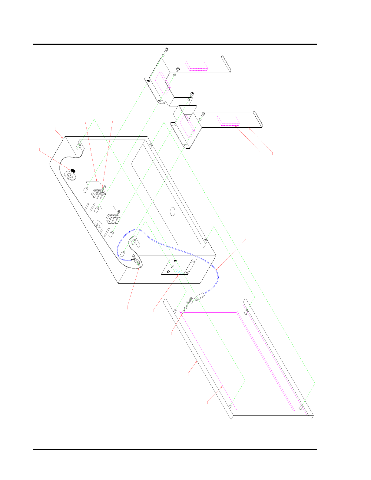
BACKBOX
DOOR
DOOR SEAL
'GORTEX' SEAL
EARTH POST
DOOR EARTH STRAP
EARTH POST
SELF ADHESIVE FOAM (4 PLACES)
Fuse:Input:Serial No:Part No:Product:Standards:Approval
:
0086
/
09
KM
95744
Fire Alarm System
Isolate Supply Before
0086
-
CPD
-
555921
Opening Cover
THIS UNIT MUST
BE EARTHED
RATING LABEL
Thorn Security Ltd
Made in Great Britian
3 WAY PSU TERMINAL
BLOCK (2 OFF)
TERMINAL BLOCK LABEL
BAT
+
BAT
-
N
/
C
THERM
THERM
N
/
C
BATTERY CLAMPS
Figure 2 – Battery clamp details
EQUIPMENT: T1216W-C
PUBLICATION: MARINEW-P-I
ISSUE No. & DATE: 1 11/12
© 2012 Thorn Security Ltd PAGE 11 of 39
Registered Company: Thorn Security Ltd. Registered Office: Dunhams Lane Letchworth Garden City Hertfordshire SG6 1BE
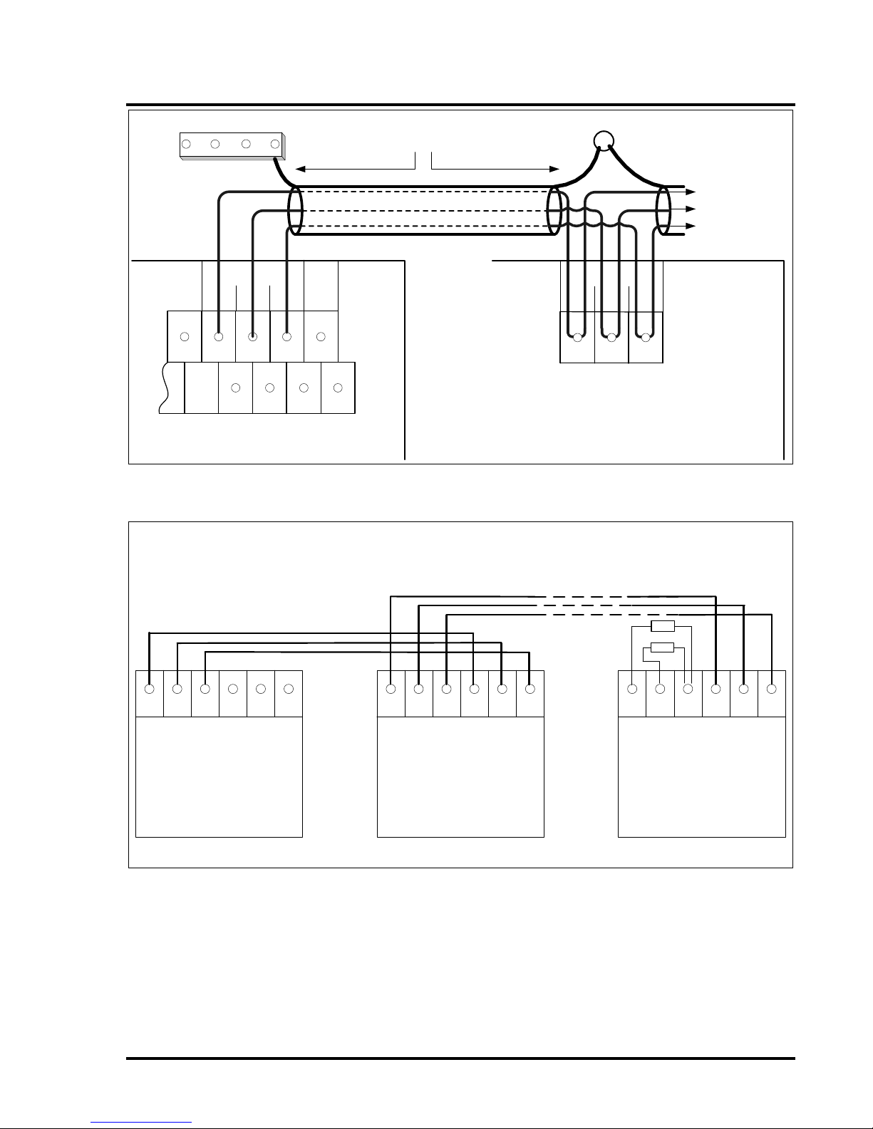
EARTH STUD
EARTH BAR
Repeater
A
B
GND
[Top right hand corner of C1627 motherboard]
Data Cable Screen
T1216W fire detection/alarm panel
Power Supply connections not shown.
Repeater
A
B
GND
T1200 repeater panel [max 5 off]
[Top right hand corner of C1626 motherboard]
Figure 3 – Repeater connection diagram
M in Sin GND GNDM out S out
C1665 Muster
Interface in Fire
Panel
M in Sin GND GNDM out S out
C1665 Muster
Interface in Repeater
Panel 1
M in Sin GND GNDM out S out
C1665 Muster
Interface in last
Repeater Panel
2 off 3k9
resistors
Wiring Optional Repeater Muster Interface[s]
These three cores should be contained within the Repeater RS485 communications cable, the cable
screen being connected to Earth at panel & repeaters. If a separate cable is used then the cable
screen should be connected to the Earth.
Figure 4 – Muster Interface Wiring Diagram
T1216W-C
MARINEW-P-I
1 11/12
PAGE 12 of 39
5.3 Modifications to the Water Mist
Relay Control Panel
Three modifications to the Water Mist Relay Control
Panel [WMRCP] are necessary to provide the
correct interface. See Modifications 1, 2 and 3 in
section 13.
These modifications should be carried out by
either the Engineer responsible for the WMRCP
or under their direct guidance and instruction.
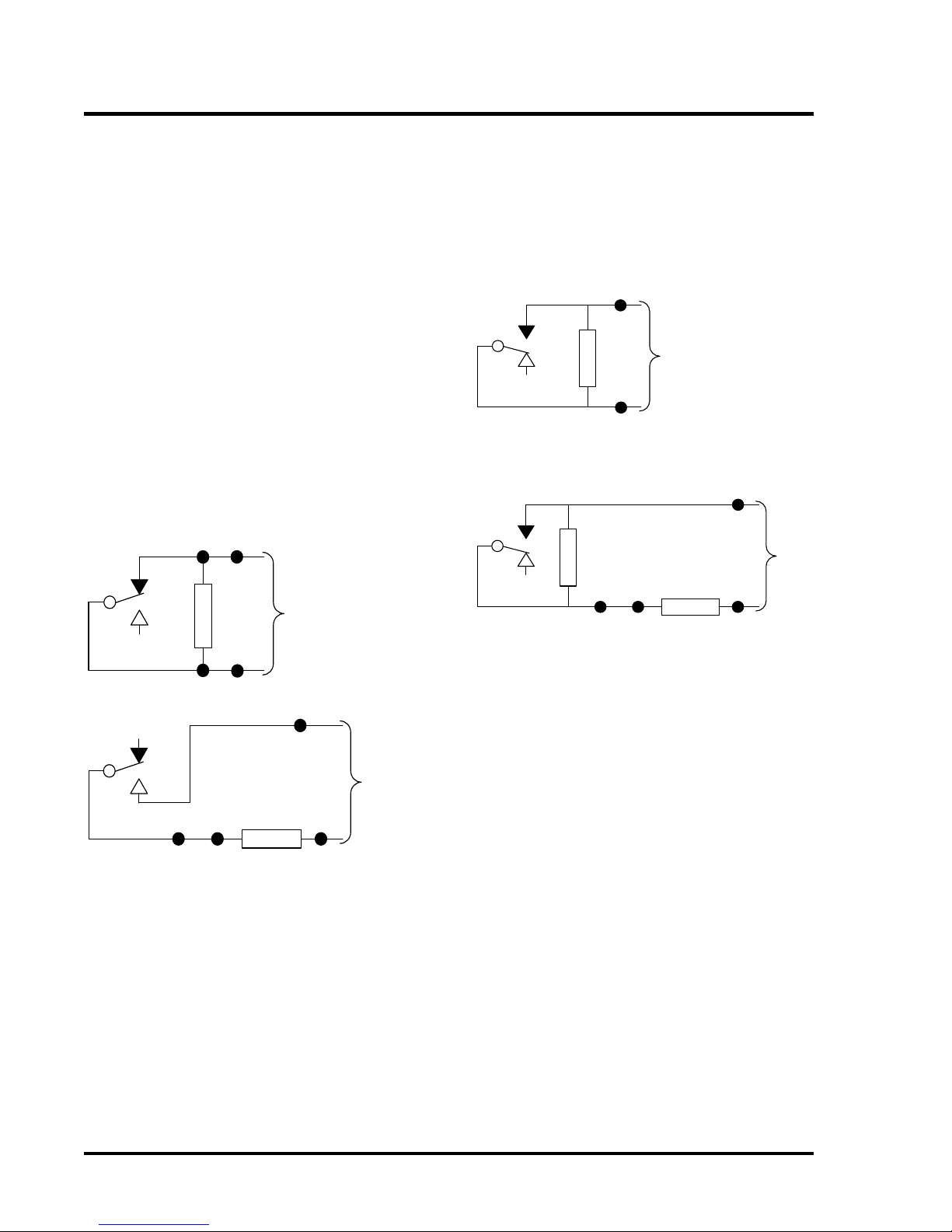
5.3.1 Modification 1 [System Abnormal]:
Refer to Figure 5 for details.
On Relay R50/2, disconnect wires 313 and 314
from the normally closed contact pair and reconnect
to the normally open pair. [Contacts described with
RL50 de-energised – i.e. in the fault condition].
Remove the 6k8 monitoring resistor connected
between wires 313 and 314. Use two spare field
terminals to connect a 10K 0.25W resistor in series
with R50/2.
6k8
Resistor
TB5/3
TB5/4
313
314
R50/2
De-energised
(fault condition)
Before Modification
10k
Resistor
TB5/3
TB5/4
313
314
R50/2
De-energised
(fault condition)
After Modification
Wire
Link
WaterMist Control Panel
System Abnormal Output Signal
U3
U4
Site Wiring to
T1216W-C
Site Wiring to
T1216W-C
Figure 5– System Abnormal Modification
5.3.2 Modification 2 [System Operated]:
Refer to Figure 6 for details.
Replace the 6k8 monitoring resistor connected
between wires 315 and 316 with a 10k 0.25W.
Use two spare field terminals to connect 680 Ohm 1
Watt resistor in series with R44/3.
6k8
Resistor
TB5/1
TB5/2
315
316
R44/3
Relay shown in
quiescent
(non-alarm)
condition
Before Modification
680 Ohm
Resistor
TB5/1
TB5/2
315
316
R44/3
After Modification
Wire
Link
WaterMist Relay Control Panel
System Operated Output Signal
U1
U2
10k
Resistor
Relay shown in
quiescent
(non-alarm)
condition
Site Wiring to
T1216W-C
Site Wiring to
T1216W-C
Figure 6– System Operated Modification
 Loading...