

Thorn security MR300 Product Application Manual

DOCUMENT CONTROL NUMBER /
© 1997 Thorn Security Limited PAGE 1 of 7
M300 SERIES
01A-02-D4
02 2/97
Registered Office: Security House The Summit Hanworth Road Sunbury-on-Thames Middlesex TW16 5DB
EQUIPMENT:
PUBLICATION:
ISSUE No. & DATE:
MR300 OPTICAL SMOKE DETECTOR RANGE
PRODUCT APPLICATION & DESIGN INFORMATION
1. INTRODUCTION
The MR300 range of optical smoke detectors forms part of the
M300 series of plug-in detectors for ceiling mounting. The
range is intended for two-wire operation on the majority of the
control equipment currently manufactured by the company. Detectors having different smoke sensitivities are offered as is an
intrinsically-safe type for use in hazardous atmospheres.
2. OPERATING PRINCIPLE
2.1 OPTICAL SYSTEM
Detectors in the MR300 range detect visible particles produced
in fires by using the light scattering properties of the particles.
All detectors in the range use the same optical system which is
shown diagrammatically in Fig. 1.
The optical system consists of an emitter and sensor, with a lens
in front of each, so arranged that their optical axes cross in the
sampling volume. The emitter, with its lens, produces a narrow
beam of light which is prevented from reaching the sensor by
the baffles. When smoke is present in the sampling volume a
proportion of the light is scattered, some of which reaches the
sensor. For a given type of smoke,
the light reaching the sensor is proportional to the smoke density. The output from the sensor can be used to activate an
alarm circuit at a pre-determined threshold.
2.2 FEA TURES OF MEASURING CHAMBER
In order to make a practical smoke detector which uses the type
of optical system described above, great care is needed in the
design of the housing. Both the optical components and the
sampling volume must be protected from the environment but
still allow smoke to enter freely into the sampling volume. The
housing must also be designed in such a way that dust settling
on its surfaces will not scatter so much light into the sensor that
false alarms are generated.
The emitter is a Gallium Arsenide [GaAs] solid state type operating at a wavelength of 0.94µm; the sensor is a silicon photodiode. These devices with their associated lenses are held
within the optical array which also provides the baffles of
Fig.1. The design of this assembly is such that the presence of
very small insects [e.g. thrips] will not cause false alarms.
Fig. 1 M300 Detector Range, Optical System
PAGE 2 of 7
M300 SERIES
01A-02-D4
002 02/96
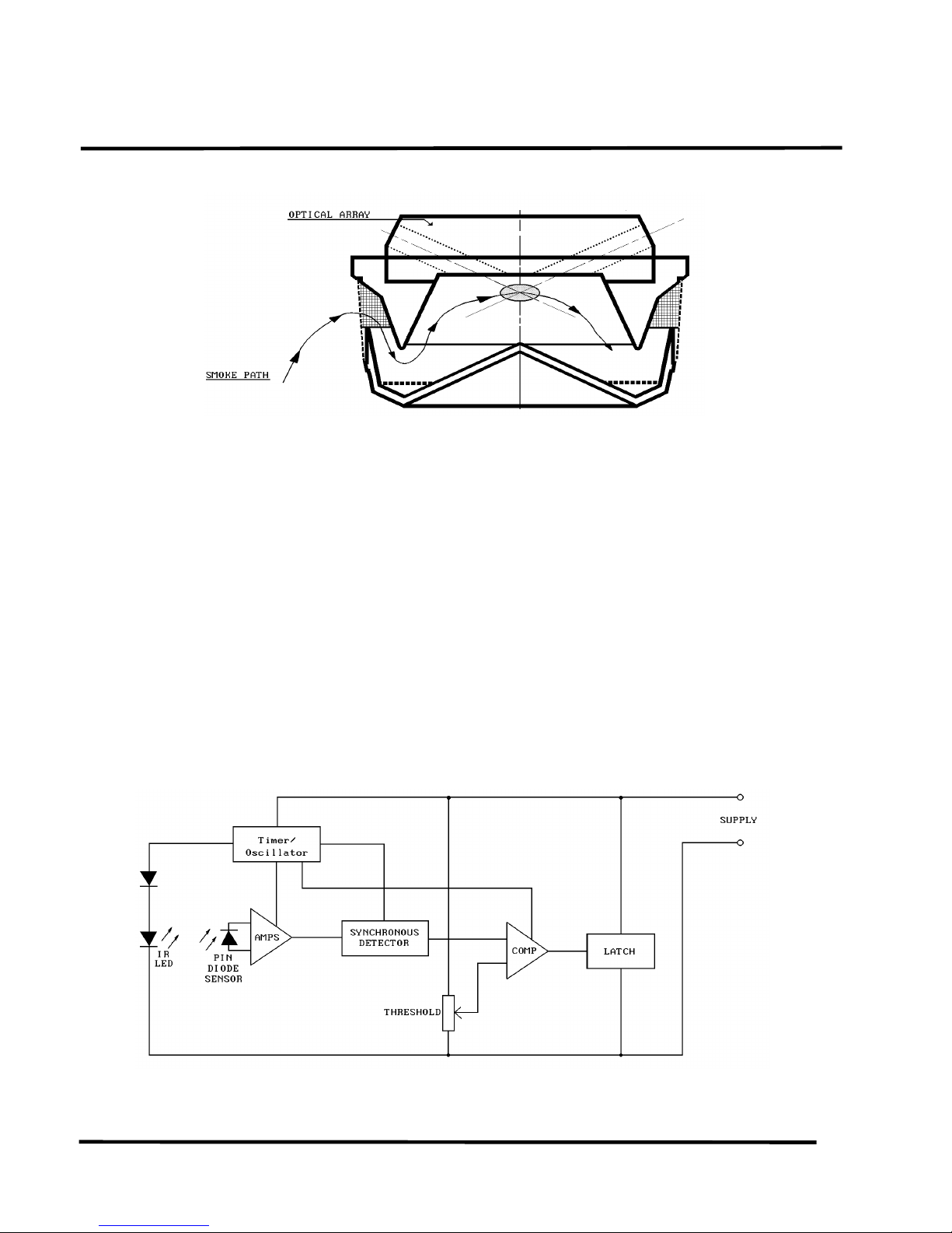
Fig. 2 Measuring Chamber Showing Smoke Flow Path
2.3 CIRCUIT OPERATIONS
A simplified block schematic of the detector is given in
Fig.3.
2.3.1 GENERAL
The GaAs emitter is pulsed every 10s in order to reduce its
power consumption. The pulse signal, as received by the silicon photodiode, is fed to a high-gain amplifier. If smoke is
present, the pulse signal received varies in proportion to the
smoke density. The output of the amplifier is thus proportional to the smoke density.
Detectors in the MR300 Range use the unique measuring
chamber shown in Fig.2.
The Sampling Volume is enclosed within a measuring chamber formed by conical labyrinth mouldings. The optical design of the chamber provides a very low background signal
in clean air conditions even when the chamber is contaminated by white dust. This high tolerance to dust is improved
even further by an aerodynamic design which encourages
dust settlement to occur on the less critical optical surfaces.
The design of the measuring chamber is patented in the UK
under the number GB 2170597 and in the USA under the
number US 4728801.
Fig. 3 Schematic Diagram of Detector

© 1997 Thorn Security Limited PAGE 3 of 7
Registered Office: Security House The Summit Hanworth Road Sunbury-on-Thames Middlesex TW16 5DB
M300 SERIES
01A-02-D4
02 2/97
EQUIPMENT:
PUBLICATION:
ISSUE No. & DATE:
Fig. 4 Exploded View of the MR300 Type Detector
 Loading...