

Thorn SensaLite SLOCS, 96239753, SensaLite SLOCSP, 96239752 Installation And Commissioning Instructions

Installation and Commissioning
Instructions
SensaLite PIR Detector for Batten-style Luminaires
SENSALITE SLOCS - Switching
SENSALITE SLOCSP - Switching with photocell
SENSALITE SLOCS (96239752)
SENSALITE SLOCSP (96239753)
Note: SENSALINK SENLP or SENSA SENP required for commissioning
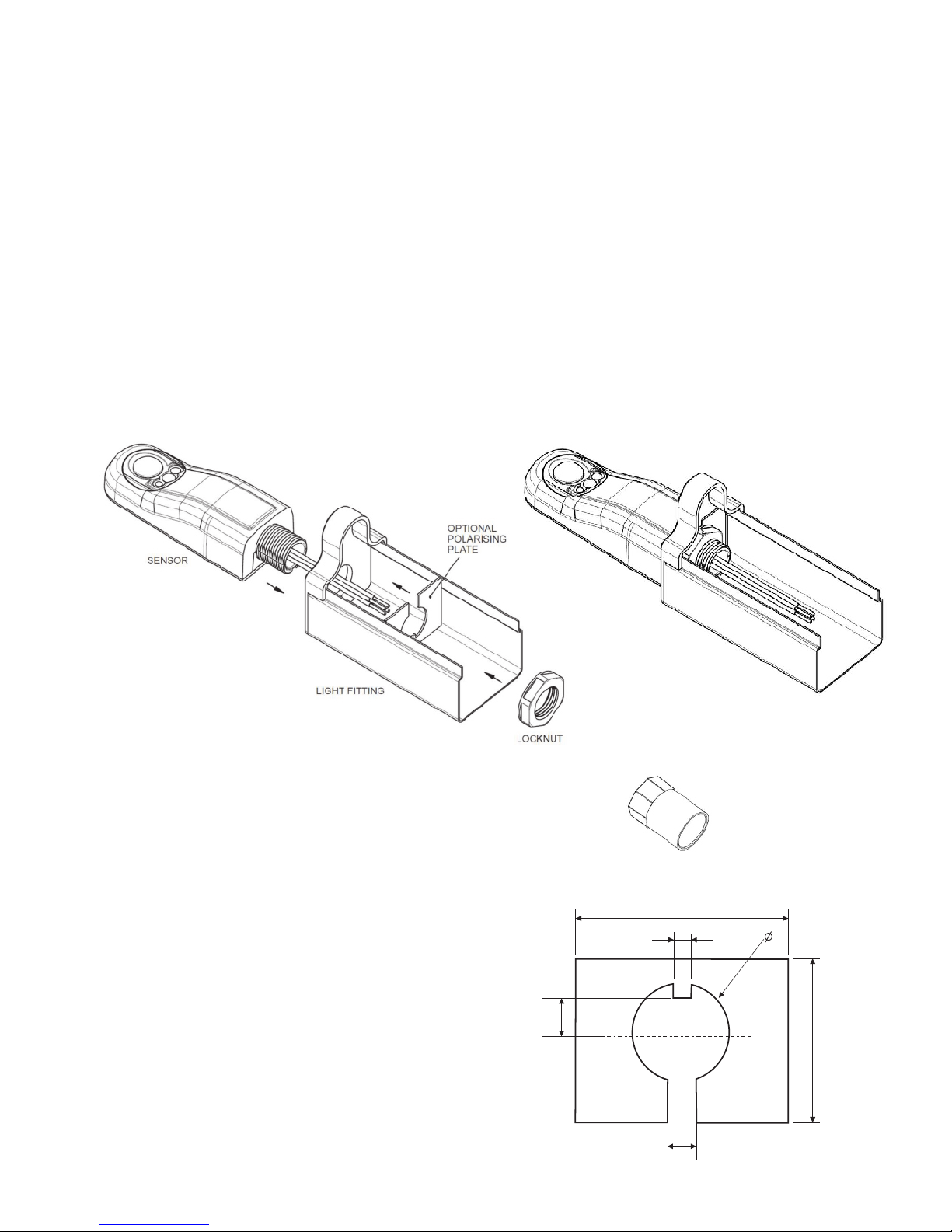
If there is insufficient space
for the locknut, the adaptor
shown below (Fig. 3) can be
used.
Fig. 3
Fig. 1
Fig. 2
SENSALINK SLOCS - Switching
SENSALINK SLOCSP - Switching with photocell
Only suitably qualified personnel should install this equipment.
This passive infrared presence detector is designed to be fitted to a batten-style luminaire.
Installation
1. Remove the M20 knockout from the end cap of the luminaire.
2. Pass the sensor wires through from the outside and insert the threaded end of the sensor into the hole.
3. A polarising plate can be made in order to prevent rotation of the sensor - an example design is given
below (Fig. 4).
4. If a polarising plate is to be used, pass the wires through the slot and position the polarising plate against
the inside face of the end cap. Ensure that the tab is positioned correctly i.e. at the ceiling side, away from
the lamp.
5. Fit and tighten the locknut.
6. Connect the wires in accordance with the wiring instructions.
Polarising Plate (not supplied)
The purpose of the polarising plate is to ensure that the sensor does
not rotate from the correct position, i.e. pointing vertically
downwards, during transport or installation.
The two overall dimensions marked ‘SEE TEXT’ need to be made
such that when the plate is positioned against the inner face of the
luminaire end cap, it cannot rotate.
The 3.5mm ‘tab’ should be located closest to the ceiling (away from
the lamp). The 6.0mm slot is optional and is to allow the wires to
pass through for ease of assembly.
Material can be plastic sheet, minimum thicknesss 1.0mm,
recommended thickness 1.5-2.0mm, or mild/stainless steel sheet,
minimum thickness 0.6mm, recommended thickness 1.0-1.6mm.
SEE TEXT
SEE TEXT
7.3
6.0
20
3.5
Fig. 4
- 2 -
20mm Female Adaptor
MK part number EFA/2
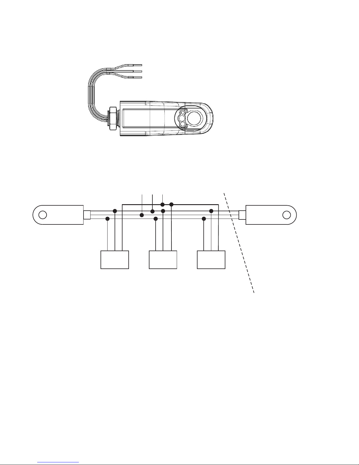
Electrical Connections
LOAD
Blue
Brown
Black
Blue
Brown
Black
Multiple Detectors
may be connected
in parallel, as is
shown above, to
control the same
Maximum Load
L N E
SUPPLY
Maximum Total Load not to exceed
that specified for a Single Detector
LOAD
LOAD
L N E
Fig. 6
W5023A
L N E L N E
Always check product label before connecting.
Black
Blue
Brown - Live
- Neutral
- Switched live
Fig. 5
- 3 -
 Loading...