


TCLDM9
5.6mm / 9mm Laser Diode Mount
Operating Manual
TCLDM9
G
LD
PD
G
THORLABS, Inc. Ph: (973) 579-7227
435 Route 206N Fax: (973) 383-8406
Newton, NJ 07860 USA www.thorlabs.com
1981-D03 REV. H 1/23/06

Table of Contents:
Description: ...........................................................................................................................................................................2
Specifications:.......................................................................................................................................................................3
Setup:.....................................................................................................................................................................................4
Laser Installation: ................................................................................................................................................................4
Laser Controller Connection:...............................................................................................................................................5
TEC Controller Connection:.................................................................................................................................................6
Mounting other Accessories:...............................................................................................................................................6
Mounting ThorLabs Fiber Coupled Pigtailed Lasers:..........................................................................................................6
The TEC Lockout and GROUND Jumpers:.........................................................................................................................7
Making the Safety Interlock Connections:...........................................................................................................................8
Operation:..............................................................................................................................................................................8
RF Modulation: ....................................................................................................................................................................8
Status and Interlocks:..........................................................................................................................................................9
Maintaining the TCLDM9:....................................................................................................................................................9
Thermistor Data: .................................................................................................................................................................10
Troubleshooting:.................................................................................................................................................................11
Table Of Figures:
Figure 1 - Location of Features...............................................................................................................................................2
Figure 2 - Polarity Switch Settings..........................................................................................................................................4
Figure 3 - LD and PD Orientation ...........................................................................................................................................4
Figure 4 - Installing Fiber Pigtailed Laser ...............................................................................................................................7
Figure 5 - Location of JMP1 and JMP2...................................................................................................................................7
Figure 6 - Remote Interlock Connector...................................................................................................................................8
Figure 7 - Thermistor Curve and Data..................................................................................................................................10
1981-D03 REV.H 1/23/06 Page 1 of 12

Description:
(
(
The TCLDM9 is a temperature-controlled laser diode mount. When used with Thorlabs LDC Series Laser Controllers and
TED Series TEC Controllers, a laser diode can be operated with preci se tempe r ature control for wavelength stability and
temperature tuning. A four pin socket accepts all 9mm and 5.6mm laser diodes. Easy to use, externally located polarity
switches allow the laser mount to be configured for all possible laser pin assignments.
The TCLDM9 was designed with features that allow it to be easily incorporated into complex systems. The front of the
TCLDM9 has a 1.035”-40 thread to accept a wide variety of Thorlabs SM1 1” optics mounts and accessorie s. Also
standard with the mount are 4-40 tapped holes on 30mm centers for mounting any number of Thorlabs cage assembly
products. Thorlabs has successfully demonstrated external cavity grating tunable lasers using the TCLDM9 and off-theshelf Thorlabs accessories.
A 50Ω RF input using a bias-tee allows the laser to be directly modulated up to 500MHz.
The TCLDM9 uses two thermo-electric coolers (TEC) to precisely regulate the operating temperature of a lase r diode.
Each TEC element is capable of up 10W of cooling at a maximum operating current of 5 Amps. The two TECs are
connected in series so that a single connection provides up to 20W of cooling. Temperature sensing is done by one of two
ways. An AD592 Temperature Transducer provides a linear temperature monitor proportional to the laser temperature in
degrees Celsius. A 10kΩ NTC thermistor is also provided for controllers that only work with thermistor feedback. The
Thorlabs TED200 supports both sensors.
Additional safety and protection features include on board reverse bias protection diodes, remote safety interlock
connection, and the TEC Lockout circuit that prevents enabling of the laser diode unless the temperature controller is also
enabled. Designed to work with our LDC and TED controllers the TEC Lockout can easily be bypassed by setting an onboard jumper.
Laser ON Indicator
LD and PD Polarity
Switches
Laser Driver Input
DB9)
TEC Driver Input
DB9)
TCLDM9
G
PD
LD
G
Figure 1 - Location of Features
RF Input (SMA)
Remote Interlock
1981-D03 REV.H 1/23/06 Page 2 of 12

Specifications:
Table 1 - TCLDM9 Specifications
Laser Specs
TEC Specs
Lasers Supported: 5.6mm & 9mm Max TEC Current: 5 A
Max. Laser Current: 2 Amps Max TEC Voltage : 4 V
Laser Pin
Configurations:
RF Modulation
Frequency:
All LD packages, switch
selectable
TEC Heating /
Cooling Capacity:
100kHz to 500MHz Typical
Temperature
Range (LD
dependent)
RF Input Impedance: Temp Sensors
50Ω AD592AN (1μA / °K)
Max. RF Power: 200mW Thermistor
Laser Polarity Select: External Slide Switches TEC Interface: DB9 Male
Laser Interface: DB9 Female
General
Size: 3.5” x 3.5” x 2”
Weight: 1.3 lb.
Accessory Mounting: 1.035-40 Thread for SM1
series optics mounts
4-40 x 30mm tapped holes
for Cage Assembly products
Miscellaneous: 8-32 and M4 Threaded
Mounting
Holes
20W
0 to 70°C
10KΩ +/- 3% @ 25°C, NTC
Beta = 3977K +/- 0.75%
1981-D03 REV.H 1/23/06 Page 3 of 12
Setup:
Laser Installation:
• Unpack the laser mount and remove the four 2-56 socket head screws from the front cover using a 5/64” hex driver.
• Remove the two Philips head 2-56 screws from the laser-mounting flange and remove the flange.
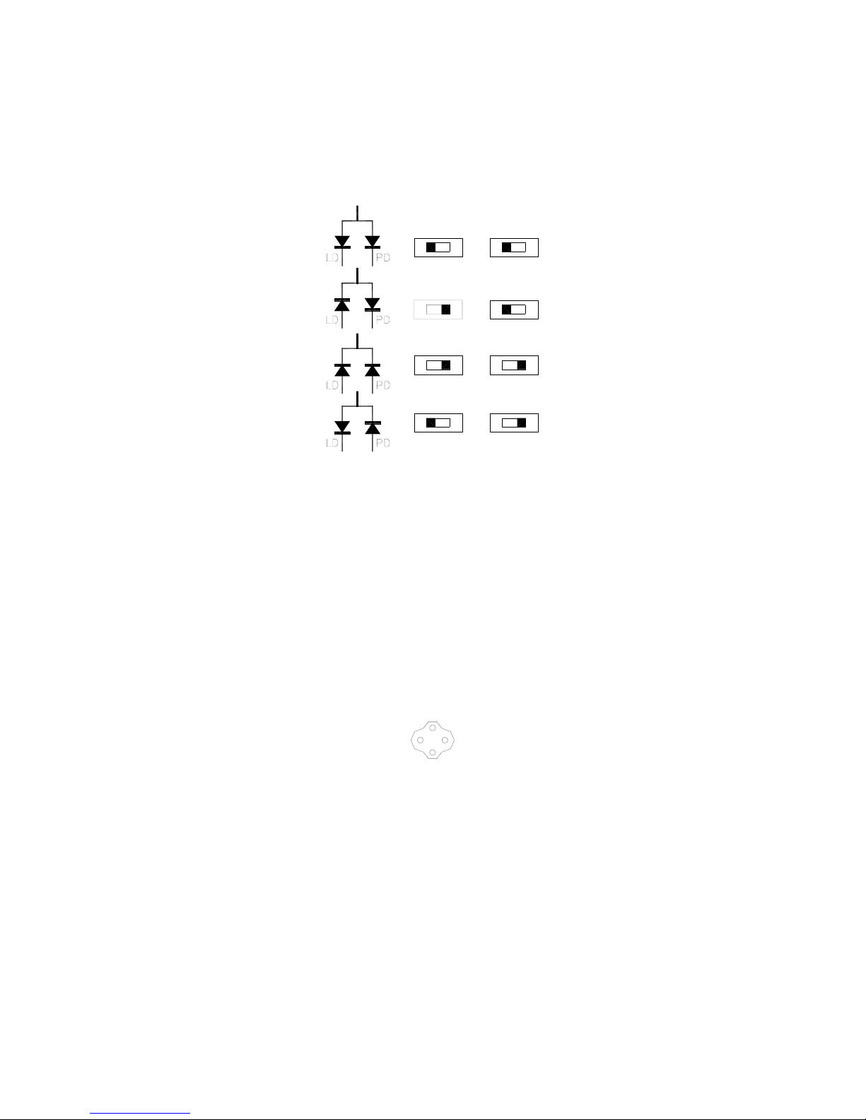
• Determine the laser pin configuration from the laser diode manufact urer’s data sheets and set the LD (Laser Diode)
and PD (Photodiode) switches located on the top of the unit according to Fig. 2.
LD
AG CG
LD PD
AG CG AG CG
AG CG AG CG
LD
AG CG
PD
CGAG
PDLD
PD
AG CG
Figure 2 - Polarity Switch Settings
• The four sockets comprising the laser diode connector are through hole type sockets with a blind clearance of 0.60”
measured from the front face of the copper cold plate. It is not necessary to trim the laser diode leads prior to
mounting into this connector unless they are longer than 0.60”.
• The laser connector is located close enough to the front face of the copper cold p l ate to allow easy installation of short
leaded lasers. The clearance area around the LD and PD sockets is sufficient to prevent the pins from contacting the
cold plate.
• Most laser diodes are three pins with the case tied to one of the laser pins and also to one of the photodiode pins. The
other laser and photodiode pin will be isolated from the case. The TCLDM9 was designed to operate the laser case at
ground potential therefore this common pin will be inserted into either the 12 o’clock or the 6 o’clock position of the
laser connector. Locate the isolated laser pin and insert it in the 3 o’clock position. The isolated photodiode should
now be in the 9 o’clock position. Refer to Fig. 3.
G
• Replace the laser mounting flange and the cover. Install both screws through the mounting flange and loo sely into the
cold plate, then carefully tighten each screw a little bit at a time until the flange is just snug. Do not over tighten either
screw – the flange will sit slightly above the cold plate. Reinstall the cover using the four 2-56 cap head screws
provided.
Special note for 4-pin laser diodes:
The TCLDM9 also supports 4-pin laser diodes. Insert the laser into the 4-pin socket and note which laser pin is in the 3
o’clock position (laser anode or cathode). Also note which photodiode pin is in the 9 o’clock position (ano de or cathode).
The mount will tie the laser and photodiode pins located at 12 o’clock and 6 o’clock together and also to ground. By noting
which polarity pins are inserted in the socket, you can convert the 4-pin layout to one of the 3-pin layouts in Fig. 1 above.
Set the LD and PD polarity switches accordingly.
1981-D03 REV.H 1/23/06 Page 4 of 12
G
LD
PD
Figure 3 - LD and PD Orientation

Laser Controller Connection:
Using the Thorlabs LDC Series Laser Controllers:
• The TCLDM9 is best used with Thorlabs LDC Series Laser Controllers. The LDC series drivers are shippe d with a
mating DB9 cable that plugs directly into the controller and laser head. Using the cable supplied with the LDC, the
controller cannot be connected incorrectly. Also, the LDC has built-in protection circuitry the protects the laser when
not in use. Simply connect the DB9 cable included with the LDC to the Laser Mount and to the controller.
• The nomenclature for the polarity switches on the LDC driver and the TCLDM 9 are consistent with each other. For
example, if the laser polarity on the driver is set to “AG” (anode grounded), then the LD polarity switch on the
TCLDM9 should also be set to AG, and so forth.
Using a third-party laser controller:
• When using a third-party controller, a custom cable will have to be made to properly interface to the laser mount.
Please refer to the table below for laser connections:
Table 2 - Laser Diode Connector Pin Functions
LD Interface
Pin
Signal Description
1 Interlock and Status Pin This pin is the input to the LD Status Indicator and Interlock Circuits.
(LDC Specific)
When using Thorlabs LDCs no external circuitry is required. To use
these features with third-party controllers please refer to the Status and
Interlock section of this manual.
5 Interlock and Status
This pin is the return side of the Status and Interlock circuitry.
Return
7 Laser Diode Cathode This pin is connected to the 3 o’clock pin on the laser socket when the
LD Polarity Switch is set to AG (Anode Grounded). Otherwise it is
floating.
8 Laser Diode Anode This pin is connected to the 3 o’clock pin on the laser socket when the
LD Polarity Switch is set to CG (Cathode Grounded). Otherwise it is
floating.
3 Laser Ground (Case) This pin is connected to the 12 o’clock and 6 o’clock pins on the laser
socket and corresponds to the settings of the LD and PD polarity
switches. i.e. If the LD and PD switches are set to AG then this pin
grounds the Anodes of the laser and photo diodes.
2 Photodiode Cathode This pin is connected to the 9 o’clock pin on the laser socket when the
PD Polarity Switch is set to AG (Anode Grounded). It is attached to
ground and the 12 o’clock and 6 o’clock pins on the laser socket when
the PD Polarity Switch is set to CG (Cathode Grounded).
4 Photodiode Anode This pin is connected to the 9 o’clock pin on the laser socket when the
6 Laser Diode Voltage
(Cathode)
PD Polarity Switch is set to CG (Cathode Grounded). It is attached to
ground and the 12 o’clock and 6 o’clock pins on the laser socket when
the PD Polarity Switch is set to AG (Anode Grounded).
This pin is connected to LD Interface Pin 7, thru a 499 Ohm resistor,
when the LD Polarity Switch is set to AG (Anode Grounded). It is
attached directly to LD Interface Pin 3 when the LD Polarity Switch is
set to CG (Cathode Grounded).
9 Laser Diode Voltage
(Anode)
This pin is connected to LD Interface Pin 8, thru a 499 Ohm resistor,
when the LD Polarity Switch is set to CG (Cathode Grounded). It is
attached directly to LD Interface Pin 3 when the LD Polarity Switch is
set to AG (Anode Grounded).
1981-D03 REV.H 1/23/06 Page 5 of 12

TEC Controller Connection:
Using the Thorlabs TED Series TEC Controllers:
• The TCLDM9 is best used with Thorlabs TED200 or related TEC Controllers. The TED series are shipped with a
mating DB9 cable that plugs directly into the controller and laser mount. Using the cable supplied with the TED, the
controller cannot be connected incorrectly. Simply connect the cable included with the TED to the Laser Mo unt and to
the controller.
Using a third-party TEC controller:
• When using a third-party controller, a custom cable will have to be made to properly interface to the laser mount.
Please refer to the table below for laser connections:
Table 3 - TEC Connector Pin Functions
TEC Interface
Pin
Signal Description
4 +TEC This pin is connected to the positive terminal of the TEC element.
5 -TEC and TEC Lockout
(-)
This pin is connected to the negative terminal of the TEC element, and
also is common to the cathode of the photo-relay of the TEC Lockout
circuit - refer to the Status and Interlock section of this manual.
1 TEC Lockout (+) This pin is connected to the anode of the photo-relay side of the TEC
Lockout circuit. When using Thorlabs TEDs no external circuitry is
required. To use these features with third-party controllers please refer
to the Status and Interlock section of this manual.
2 +Thermistor
The 10KΩ @ 25°C NTC thermistor (provided for temperature feedback).
3 -Thermistor The thermistor return pin.
7 AD592(-) The negative terminal of the AD592 temperature transducer. When
using Thorlabs TEDs no external circuitry is required. To use this device
with third party controllers it must be properly biased. Refer to Analog
Devices AD592 Data for application information.
9 AD592(+) The positive terminal of the AD592
6 n.c.
8 n.c.
Mounting other Accessories:
The TCLDM9 includes a 1.035-40 threaded hole centered on the laser for mounting Thorlabs SM1-series optics mounts.
This is most often used for mounting aspheric collimating optics available separately from Thorlabs.
Also included are four 4-40 tapped holes mounted on 30mm centers for attaching Thorlabs cage assembly products.
Using the combination of the SM1 threaded mount and the cage assemblies’ products, a wide variety of optical systems
can be easily assembled form off-the-shelf products. In one such example, Thorlabs successfully built an external cavity
grating tunable laser used for atomic spectroscopy experiments. For more information and oth er examples please call
Thorlabs and an engineer will be happy to assist you.
Mounting ThorLabs Fiber Coupled Pigtailed Lasers:
Use the Pigtail Adapter clamp to hold the pigtail housing onto the TCLDM9 cold-plate. Referring to Fig. 4, first install the
pigtailed laser into the TCLDM9 socket, observing the proper polarity of the laser to the socket (the pigtail’s pin-outs are
provided with the pigtail data sheet). If installed properly the flange of the pigtail will look as shown in Fig. 4A. It may be
necessary to trim or remove the foam cold-plate insulator.
Make sure the pigtail’s laser diode leads are fully inserted into the socket and then slide the FC conne ctor and optical fiber
of the Pigtail through the opening in the Pigtail Mounting Adapter. Draw the optical fiber through the opening and slide the
adapter over the pigtail housing, aligning the slot in the adapter with the flange on the Pigtail housing (Fig. 4B). The
mounting holes on the adapter should now be lined up with the threaded holes on the TCLDM9 cold-plate (Fig. 4C).
Secure the adapter to the cold-plate using two (2) 2-56 x 3/8” cap head screws provide with the adapter. Start each screw
into its respective mounting thread and tighten until just snug (do not over tighten), alternating between the two screws to
ensure that the adapter is tightened evenly onto the Pigtail flange.
1981-D03 REV.H 1/23/06 Page 6 of 12

Pigtail Flange
Screws
Adapter
Fig. 4A
Fig. 4B
Figure 4 - Installing Fiber Pigtailed Laser
The TEC Lockout and GROUND Jumpers:
Two jumpers, JMP1 and JMP2, are located under the cover on the main PCB assembly. JMP1 allows you to enable or
bypass the TEC Lockout feature. This feature, when enabled, will prevent the laser diode from being turned on unless the
TEC controller is enabled. The unit is shipped from the factory with the TEC Lockout feature BYPASSED. To enable the
TEC Lockout simply remove the cover of the unit and remove the blue jumper from the JMP1 header. The jumper can be
placed on one or the other header pins for safe keeping.
An optional ground jumper is also provided to allow connecting the system ground node (common to the “G” pins of the
laser diode connector) to the metal housing of the unit, which is also connected to the shields of the LD and TEC input
cables. Care should be taken when using this connection as unwanted ground loops may be formed. The unit is shipped
from the factory with JMP2 disconnected. To close this connection remove the cover of the unit and place the blue
jumper onto both pins of the JMP2 header.
TEC Lockout Jumper
Fig. 4C
Ground Jumper
1981-D03 REV.H 1/23/06 Page 7 of 12
Figure 5 - Location of JMP1 and JMP2

Making the Safety Interlock Connections:
The TCLDM9 is equipped with a Remote Interlock connector located on the sid e panel. In order to enable the laser
source, a short circuit must be applied across the terminals of the Remote Interlock connector. In practice this connection
is made available to allow the user to connect a remote actuated switch to the connector (i.e. an open door indicator). The
switch (which must be normally open) has to be closed in order for the unit to be enabled. Once the switch is in an open
state the laser diode must automatically shutdown.
All units shipped from Thorlabs are configured with a shorting device installed in the Interlock connector. If you are not
going to use this feature then you can leave the shorting device installed and the unit will operate normally as described in
the procedures in this manual. If you wish to make use of the Interlock feature you will need to acquire the appropriate
connector mate and wire it your remote interlock switch. Next, remove the shorting device by unscrewing it from the input
and install the connector into the Interlock input.
The Interlock input only accepts a 2.5mm mono phono jack. This connector is readily available at most electronics
stores (Radio Shack, Digikey, Mouser, Allied to name a few).
The electrical specifications for the Interlock input are as follows:
Type of Mating Connector: 2.5mm mono phono jack
Open Circuit Voltage: +5VDC with respect to system ground (when used in conjunctio n with Thorlabs drivers)
Short Circuit Current: 10mADC Typical
Connector Polarity: Tip is positive, Barrel is ground
Interlock Switch Requirements: Must be N.O. dry contacts (under no circumstances should a ny external voltages be
applied to the Interlock input)
Figure 6 - Remote Interlock Connector
Operation:
• With the laser mounted and the laser controller and temperature controller connected, the TCLDM9 is ready to
operate. Please refer to the operating instructions for the laser and temperature controller for specific operating
instructions.
• When operating at low temperatures in high humidity climates the laser mount may develop internal condensation. If
this occurs, turn the laser off, open the case and allow the mount to dry off completely before re-using.
• When using a collimating optic in the 1” threaded mount, the lens may be positioned slightly laterally by loosening the
four 2-56 screws on the cover and shifting the cover plate manually.
RF Modulation:
The TCLDM9 has an RF input for modulating the laser with an external RF source up to 500 MHz. This is a 50Ω input that
is AC-coupled directly to the laser through a Bias-Tee network. To calculate the desired RF power to modulate the laser
determine the amount of modulating current needed from the laser manufacturer’s data sheets and use the following
calculations:
RF Voltage = (Laser Diode Modulating Current) * 50Ω
It is strongly recommended that you start off conservatively by a factor of 10 below the calculated modulating voltage and
slowly bring the RF power up until the desired depth of modulation is reached.
Use the laser controller to establish the DC operating point of the laser.
WARNING: The RF input is directly coupled to the laser. Any excessive transients or noise will be coupled into the laser
and may cause the laser to be overdriven. Also, the laser can be easily overdriven if excessive RF power is applied to this
input. Use the RF modulation input with care to avoid damaging your laser.
1981-D03 REV.H 1/23/06 Page 8 of 12

Status and Interlocks:
This unit is equipped with two interlock circuits and an LED that indicates if the laser diode is enabled. All three circuits
are designed to interface with Thorlab’s Laser and TEC controllers with no external circuitry.
If third party controllers are used to drive the laser diode or TEC elements then ONLY the LD ON indicator can be used.
To prevent damage to the Status and Interlock circuits the following external connections should be followed:
- Install the shorting device into the REMOTE INTRLK connector that was shipped with the TCLDM9.
- Install the TEC LOCKOUT bypass jumper into JMP1 inside the TCLDM9. (See “The TEC Lockout and
GROUND Jumpers” above).
- Connect a resistor to LD Interface DB9 Pin 1 appropriately sized to limit the current into Pin 1 to between 5 –
10mA.
- The “driver” side of this resistor should be connected to a DC signal that, when high, indicates that the laser
diode is being driven.
- If you have any questions regarding these connections please feel free to contact an engineer at Thorlabs for
clarification.
If you wish to make full use all of the Status and Interlock features with your third party drivers please contact Thorlabs
and an engineer will help you determine if this is possible and how to implement these features.
Maintaining the TCLDM9:
There are no serviceable parts in the TCLDM9. The housing may be cleaned by wiping with a soft damp cloth. If you
suspect a problem with your TCLDM9 please call Thorlabs and an engineer will be happy to assist you.
1981-D03 REV.H 1/23/06 Page 9 of 12

Thermistor Data:
35000
30000
25000
20000
15000
Resistance (Ohms)
10000
5000
0
1
Thermistor Resistance vs. Temperature
4
7
10
13
16
19
22
25
28
31
34
37
40
43
46
49
52
55
58
61
64
67
70
Degrees C
Figure 7 - Thermistor Curve and Data
Resistance (Ohms) Degrees C
15895 15
15153 16
14451 17
13785 18
13155 19
12558 20
11991 21
11454 22
10944 23
10460 24
10000 25
9563 26
9149 27
8755 28
8380 29
8023 30
7684 31
7362 32
7055 33
6762 34
6484 35
1981-D03 REV.H 1/23/06 Page 10 of 12

Troubleshooting:
1) Laser Driver will not enable.
- If you are using Thorlabs Laser and TEC controllers with your TCLDM9 mount….
o Remote Interlock is open.
Make sure that either the “shorting device” is installed in the REMOTE INTRLK connector on the side
of the TCLDM9. If you have a remote interlock switch connected to this REMOTE INTRLK connector
it must be in a closed position.
o TEC LOCKOUT circuit is active and the TED series TEC controller is not enabled.
To determine if you have selected the TEC LOCKOUT circuit to be active refer to The TEC Lockout
and GROUND Jumpers section and Fig. 4. If it is selected then the TED series TEC controller must
be enabled first before the LDC series laser controller can be enabled.
2) Laser wavelength or power is unstable even though the TEC controller shows a stable temperat ure…
- Make sure your laser diode is fully inserted into the TCLDM9 laser socket and its body is in full contact with
the copper cold plate.
- Make sure the appropriate mounting flange is installed over your laser. There are two different flanges; one
specifically for 5.6mm diodes and one for 9mm diodes.
3) The LDC series laser driver indicates an “Open Circuit” alarm when I you try to enable the laser….
- The LD and PD polarity switch settings are incorrect. Refer to Fig.2 and the data sheet for your specific laser
diode to ensure the proper settings. The LD polarity switch setting on your TCLDM9 must also match the LD
polarity switch setting on the rear panel of your LDC series laser diode controller.
- The laser diode is installed into the wrong pins on the laser diode socket. Refer to Fig. 3 for the correct
orientation of the laser diode pins and compare this to the data sheet for your laser diode.
4) My laser diode does not have an integrated photodiode, how does it get installed and how do the polarity switche s
get set?
- If your laser diode has one of its two active leads common to the case of the laser, that lead must be
connected to one of the “G” sockets on the laser diode connector (refer to Fig. 3) while the other pin is
connected to the “LD” socket in the 3 o’clock position. Depending on the pin orientation of your laser you
might be using either the “G” socket at 12 o’clock or the “G” socket at 6 o’clock. Refer to your laser diode
data for pin orientation. If your Cathode pin is common to the body of your laser diode, set the LD polarity
switch to “CG”. If your Anode pin is common to the body of your laser diode, set the LD polarity switch to
“AG”. The setting for the PD polarity switch is irrelevant.
If you still have problems or questions regarding the operation of your TCLDM9 please feel free to call ThorLabs,
Inc. and ask for TECH SUPPORT.
1981-D03 REV.H 1/23/06 Page 11 of 12

WEEE
As required by the WEEE (Waste Electrical and Electronic Equipment Directive) of the European
Community and the corresponding national laws, Thorlabs offers all end users in the EC the
possibility to return “end of life” units without incurring disposal charges.
This offer is valid for Thorlabs electrical and electronic equipment
• sold after August 13th 2005
• marked correspondingly with the crossed out “wheelie bin” logo (see fig. 1)
• sold to a company or institute within the EC
• currently owned by a company or institute within the EC
• still complete, not disassembled and not contaminated
As the WEEE directive applies to self contained operational electrical and electronic products, this “end of life” take back
service does not refer to other Thorlabs products, such as
• pure OEM products, that means assemblies to be built into a unit by the user (e. g. OEM laser driver ca rds)
• components
• mechanics and optics
• left over parts of units disassembled by the user (PCB’s, housings etc.).
If you wish to return a Thorlabs unit for waste recovery, please contact Thorlabs or your nearest dealer for further
information.
Waste treatment on your own responsibility
If you do not return an “end of life” unit to Thorlabs, you must hand it to a company specialized in
waste recovery. Do not dispose of the unit in a litter bin or at a public waste disposal site.
Ecological background
It is well known that WEEE pollutes the environment by releasing toxic products during decomposition. The aim of the
European RoHS directive is to reduce the content of toxic substances in electronic products in the future.
The intent of the WEEE directive is to enforce the recycling of WEEE. A controlled recycling of end of live products will
thereby avoid negative impacts on the environment.
1981-D03 REV.H 1/23/06 Page 12 of 12
Crossed out “wheelie bin” symbol
 Loading...