

Page 1
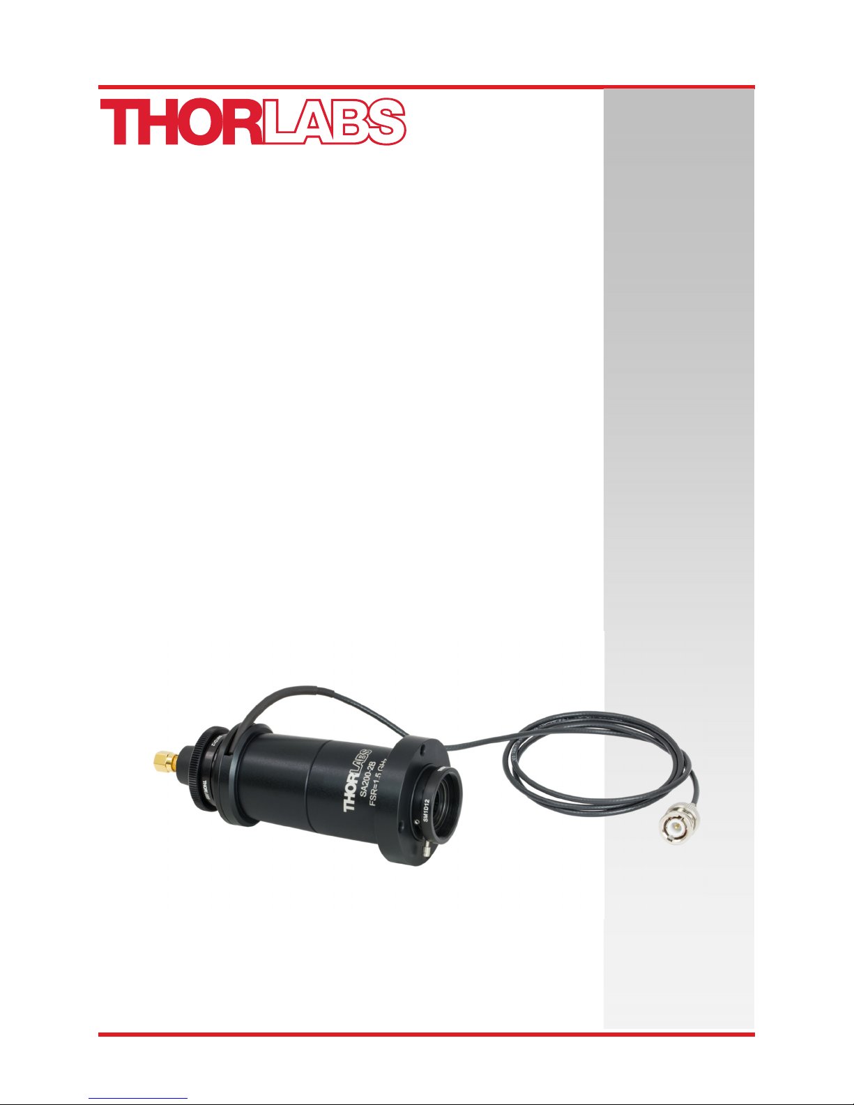
SA200 Series
Fabry Perot
Interferometer
User Guide
Page 2

Fabry-Perot Interferometer
Table of Contents
Chapter 1 Warning Symbol Definitions..................................................................................1
Chapter 2 Safety........................................................................................................................2
Chapter 3 Fabry-Pérot Interferometry....................................................................................3
3.1. Free Spectral Range ............................................................................................ 3
3.2. Finesse and Resolution ...................................................................................... 4
Chapter 4 Setup and Procedures............................................................................................5
4.1. Recommended Setup For SA200 Interferometers Except SA200-30C ........... 5
4.2. Recommended Setup for the SA200-30C Interferometer ................................ 6
4.3. Alignment ............................................................................................................. 6
4.4. Calibration of the time scale............................................................................... 7
4.5. Spectrum Analyzer Controller ............................................................................ 7
Chapter 5 Specifications..........................................................................................................8
Chapter 6 Mechanical Drawing................................................................................................9
Chapter 7 Regulatory..............................................................................................................10
Chapter 8 Thorlabs Worldwide Contacts.............................................................................11
Page 3

Page 4
Fabry-Perot Interferometer Chapter 1: Warning Symbol Definitions
Chapter 1 Warning Symbol Definitions
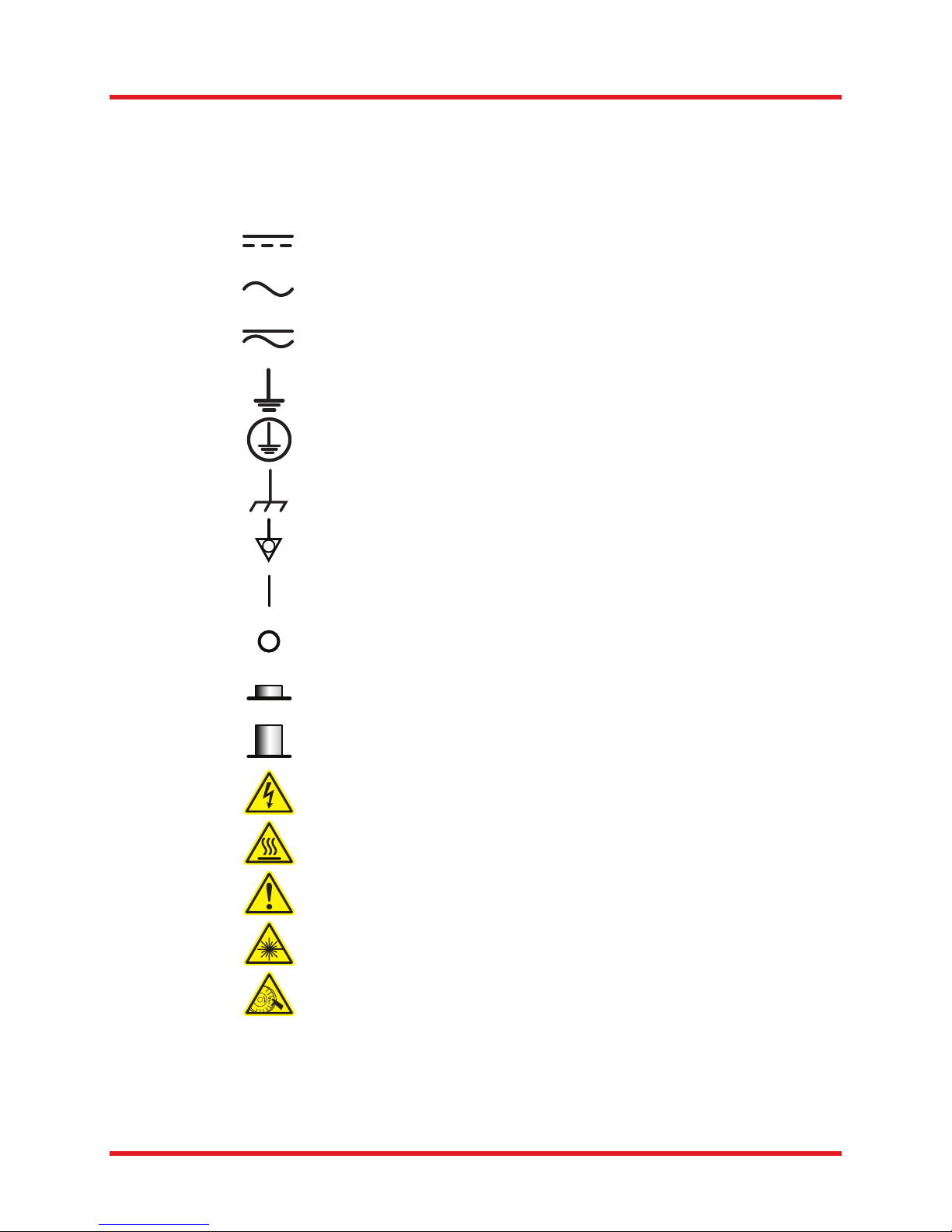
Below is a list of warning symbols you may encounter in this manual or on your device.
Symbol Description
Direct Current
Alternating Current
Both Direct and Alternating Current
Earth Ground Terminal
Protective Conductor Terminal
Frame or Chassis Terminal
Equipotentiality
On (Supply)
Off (Supply)
In Position of a Bi-Stable Push Control
Out Position of a Bi-Stable Push Control
Caution: Risk of Electric Shock
Caution: Hot Surface
Caution: Risk of Danger
Warning: Laser Radiation
Rev C, December 3, 2018 Page 1
Caution: Spinning Blades May Cause Harm
Page 5

Fabry-Perot Interferometer Chapter 2: Safety
Chapter 2 Safety
All statements regarding safety of operation and technical data in this instruction manual will only apply
when the unit is operated correctly. Please read the following warnings and cautions carefully before
operating the device.
WARNING
Take appropriate measures for eye safety.
Never look directly into the beam, not even at the output of the SA200.
SHOCK WARNING
Never touch the output of the SA200 PZT driving unit.
Page 2 STN051087-D02
Page 6
Fabry-Perot Interferometer Chapter 3: Fabry-Pérot Interferometry
Chapter 3 Fabry-Pérot Interferometry
The SA200 is a high finesse Spectrum Analyzer used to examine the fine structures of the spectral
characteristics of CW lasers. The spectrum analyzer consists of a confocal cavity that contains two high
reflectivity mirrors; by varying the mirror separation with a piezoelectric transducer the cavity acts as a very
narrow band-pass filter. Knowing the free spectral range of the SA200 allows the time-base of an
oscilloscope to be calibrated to facilitate quantitative measurements of a laser line shape. The confocal
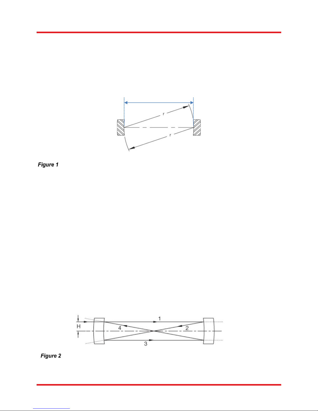
cavity design, for which the mirror spacing, d, and radius, r, are identical, allows for an easy alignment
procedure. Mirrors shown below are AR coated on the outer surfaces and HR coated on the inner surfaces.
Illustration of the confocal cavity design, where the mirror spacing is chosen equal
to the radius of curvature of the mirrors.
d
3.1. Free Spectral Range
To scan the spectra of the laser beam entering the Scanning Fabry-Pérot interferometer, a small
displacement is applied to one of the cavity mirrors mounted on the piezoelectric transducers. This is done
by fine tuning the ramp voltage applied to the piezoelectric elements using the controller SA201. When the
mirror spacing becomes equal to an integral number of half the wavelength of the laser, constructive
interferences occur. That spectral response of the signal can be visualized with a scope. A series of
periodical peaks appear on the screen of the scope. The distance between consecutive peaks is called the
free spectral range (FSR) of the instrument.
From a user's perspective, the free spectral range of a confocal cavity is given by
FSR = c/4d,
where c is the speed of light and d is the cavity length, instead of c/2d as would be the case for a planoplano cavity; the factor of 2 in the denominator can be understood by inspecting the ray trace shown on the
next page in Figure 2. Note that a ray entering the cavity at a height ‘H’ parallel to the optical axis of the
cavity makes a triangular figure eight pattern as it traverses the cavity. From this pattern it is clear that the
ray makes four reflections from the cavity mirrors instead of the two that would result in a plano-plano cavity.
Hence the total round-trip path through the cavity is given as 4d instead of 2d.
This figure shows a simplified ray-trace for a ray entering the cavity at height ‘H’.
The curvature of the mirrors ‘r’ and the separation being set precisely to ‘r’ ensures that the
input ray is imaged back onto itself after traveling a distance of approximately 4r.
Rev C, December 3, 2018 Page 3
Page 7
Fabry-Perot Interferometer Chapter 3: Fabry-Pérot Interferometry
Additionally, in this configuration if a paraxial ray is traced through the system as shown Figure 2, it is
apparent that in the confocal configuration each mirror serves to image the other mirror back onto itself so
that a ray entering the cavity will, after four traverses of the cavity, fall back onto itself (keep in mind that
the focal length of a spherical mirror is r/2). This imaging of the beam back onto itself greatly simplifies the
alignment of the cavity; just align your input to within a few tenths of a millimeter to the center of the mirror
set and restrict your input angles to less than a few degrees. The SA200 series interferometer has two iris
diaphragms that simplify this alignment requirement.
3.2. Finesse and Resolution
The finesse, F, of the Scanning Fabry-Perot interferometer is a quantity which characterizes the ability of
the interferometer to resolve closely spaced spectral features, and it is determined solely by the reflectivity
of the mirrors involved. For an infinitely narrow input spectrum, the finesse determines the width of the
measured spectrum. In combination with the mirror spacing and its resulting free spectral range, the finesse
defines the resolution of the instrument by
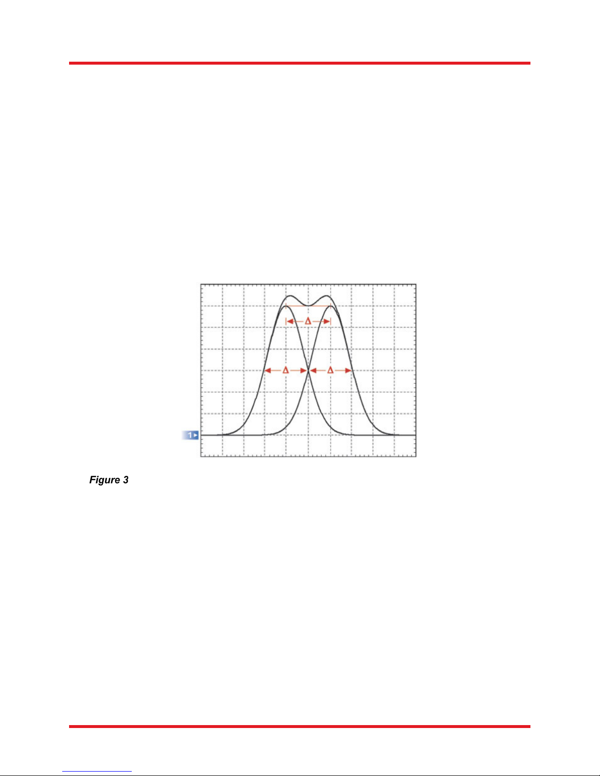
Δ = FSR/F.
When two equal Gaussian lineshapes just meet the Taylor criteria for being
resolvable, they are separated by their common FWHM (Δ) as shown in the plot.
High finesse means high resolution capability, and high finesse is obtained by increasing the reflectivity of
the cavity mirrors. However, highly reflective mirrors reduce the transmission of the interferometer. Still,
typical peak-transmission values are in the range from 20-60% of the input power, depending on both the
SA200 model and the particular set of mirrors used.
Page 4 STN051087-D02
Page 8
Fabry-Perot Interferometer Chapter 4: Setup and Procedures
Chapter 4 Setup and Procedures
4.1. Recommended Setup For SA200 Interferometers Except SA200-30C
The SA200 should be mounted in a Ø2" kinematic mirror mount, such as Thorlabs' KM200, so that it can
be easily adjusted. In many applications, it is useful to direct the beam into the Fabry-Perot interferometer
with the use of a mirror in a kinematic mirror mount, on a flip platform mount. A lens with focal length of
250 mm can be used, with the focus set roughly at the center of the housing, approximately 30 mm past
the flange. If the detector is connected directly to the scope, a 5 kΩ terminator is needed.
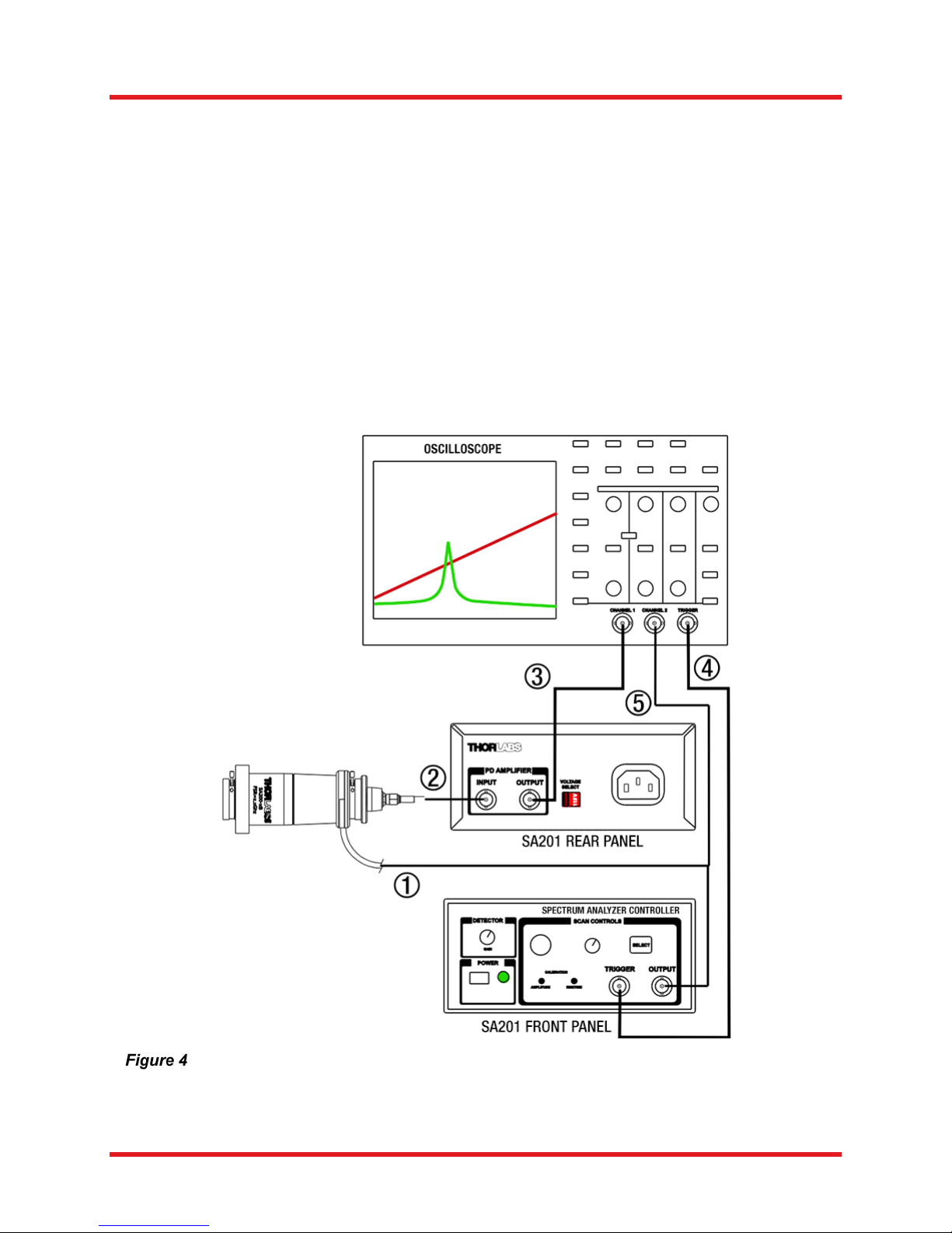
In a typical application, the SA200 Interferometer is used in conjunction with a signal generator and an
oscilloscope, as shown below. The signal generator should be able to produce either a triangle or sawtooth wave with an adjustable frequency (5 to 50 Hz), an adjustable amplitude, and an adjustable offset
(Thorlabs SA201 Fabry-Perot Controller is used for generating the required scan signals for obtaining the
data in this document). The maximum voltage on the piezo (ramp in) is not to exceed 150 V. The signal
generator is used to repeatedly scan the length of the cavity in order to sweep through the transmission
spectrum of the interferometer. An oscilloscope is typically used to view the spectrum and make quantified
measurements of spectral features.
Schematic of a recommended setup for using an SA200 series interferometer in
combination with a SA201 controller (not for the SA200-30C; see below).
Rev C, December 3, 2018 Page 5
Page 9
Fabry-Perot Interferometer Chapter 4: Setup and Procedures
4.2. Recommended Setup for the SA200-30C Interferometer
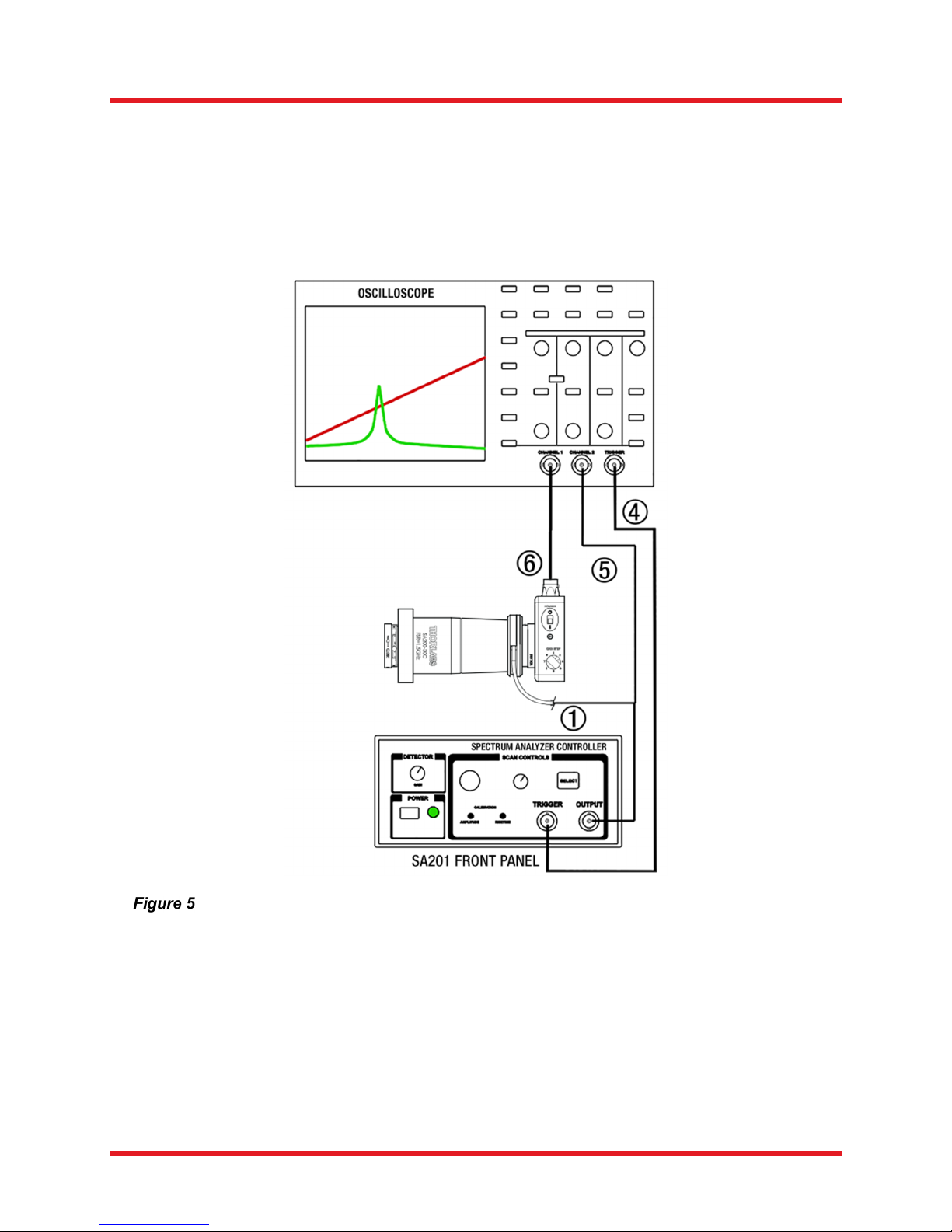
The SA200-30C is recommended to be used in combination with the PDAVJ5 detector. To get started,
remove the protection cap from the detector and mount the detector onto the output iris thread of the SA20030C. Note that the PDAVJ5 already provides a transimpedance amplification stage; therefore, the output
of the detector can be directly connected to an oscilloscope and must not be connected to the “PD amplifier
input” port of the SA201 controller. For details on the use of the PDAVJ5, please refer to its manual, which
can be found on the Thorlabs website. Due to saturation effects of the diode inside the PDAVJ5 detector,
the optical power entering the SA200-30C should be kept below 200 µW in order to avoid saturation.
Schematic of a recommended setup for using an SA200-30C interferometer in
4.3. Alignment
To align the SA200 Series Fabry-Perot interferometer, follow the steps for the recommended setup as
described in Section 4.1 or 4.2 above. Next, close the input iris to its minimum aperture and center the
beam on the iris opening, which most conveniently is achieved by aligning the beam via two folding mirrors
onto the input iris. Leave the back iris completely open and start to scan the unit. Make sure that a full
sweep is visible on the oscilloscope, as well as that the signal from the detector is displayed; for ignition
alignment adjust the oscilloscope gain to maximize sensitivity.
Page 6 STN051087-D02
combination with a SA201 controller
Page 10

Fabry-Perot Interferometer Chapter 4: Setup and Procedures
Use the mirror mount's tip/tilt adjustment until the beam is centered through the body of the SA200, i.e. until
you start to see modes on the oscilloscope. Slowly close the back iris while adjusting the mirror mount to
keep the beam in the center of the device. Once the beam is centered, the alignment can be fine tuned with
the two input mirrors by monitoring the shape and size of the transmission modes on the oscilloscope. The
interferometer will then be ready for measurements.
4.4. Calibration of the time scale
Knowing the free spectral range (FSR) of the SA200 allows the time-base of an oscilloscope to be calibrated
to facilitate quantitative measurements of laser line shape. Due to the interferometers' resolution of
7.5 MHz, the fine structure resulting from multiple longitudinal modes of a laser line can be resolved.
4.5. Spectrum Analyzer Controller
The SA201 controller generates a voltage ramp, which is used to scan the separation between the two
cavity mirrors. A photodiode is used to monitor transmission of the cavity. Using the output sync signal
from the controller, an oscilloscope can be used to display the spectrum of the input laser. The controller
provides adjustment of the ramp voltage (1 to 30 V), offset (0 to 15 VDC), and scan-time (0.01 - 10 s) to
allow the user to choose the scan range and speed. Offset control is provided to allow the spectrum
displayed on the oscilloscope to be shifted right or left, and zoom capability provides up to 100X increase
in spectral resolution.
Rev C, December 3, 2018 Page 7
Page 11

Fabry-Perot Interferometer Chapter 5: Specifications
Chapter 5 Specifications
Optical Performance Specifications
Maximum Input Voltage
Free Spectral Range1
Minimum Finesse
Resolution
Outer Housing Material
Fabry-Perot Cavity Material2
Dimensions (SA200 Models Except SA200-30C)
Dimensions (SA200-30C)
Available Coating Ranges for the SA200 series
Item # Coating Wavelength Range
SA200-2B
SA200-3B
SA200-5B
SA200-8B
SA200-12B
SA200-18C
SA200-30C
290 - 355 nm & 520 - 545 nm (Dual Band)
>200 (minimum), 250 (typical)
Black Anodized Aluminum
Low Thermal Expansion Invar
350 - 535 nm
535 - 820 nm
820 - 1275 nm
1275 - 2000 nm
1800 - 2600 nm
3000 - 4400 nm
150 V
1.5 GHz
7.5 MHz
Ø2" Flange
Total Length: 5.85"
Ø2" Flange
Total Length: 4.07"
®
1
FSR is set by the length of the confocal cavity and is given by: FSR = c/4d, where d is the radius of curvature of the mirrors; in this
case d = 50 mm.
2
A thermal design balances the small coefficient of thermal expansion of the Invar body with the negative coefficient of thermal
expansion of the piezo actuators.
Page 8 STN051087-D02
Page 12
Fabry-Perot Interferometer Chapter 6: Mechanical Drawing
Chapter 6 Mechanical Drawing
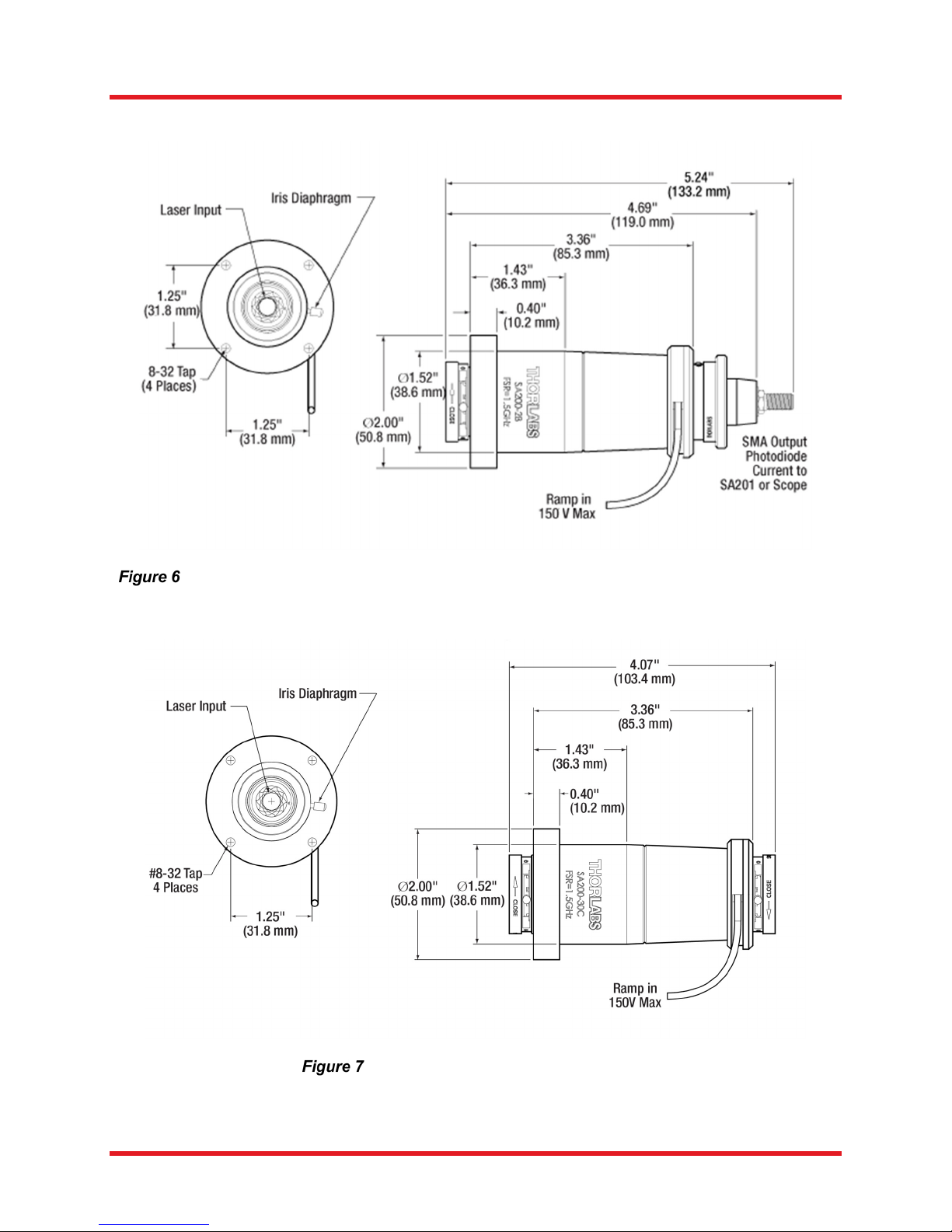
All SA200 models share the same housing, except for the SA200-30C (see below).
Rev C, December 3, 2018 Page 9
SA200-30C Mechanical Drawing
Page 13

Fabry-Perot Interferometer Chapter 7: Regulatory
Chapter 7 Regulatory
As required by the WEEE (Waste Electrical and Electronic Equipment Directive) of the European
Community and the corresponding national laws, Thorlabs offers all end users in the EC the possibility to
return “end of life” units without incurring disposal charges.
This offer is valid for Thorlabs electrical and electronic equipment:
Sold after August 13, 2005
Marked correspondingly with the crossed out “wheelie bin” logo (see right)
Sold to a company or institute within the EC
Currently owned by a company or institute within the EC
Still complete, not disassembled and not contaminated
As the WEEE directive applies to self-contained operational electrical and electronic products, this end of
life take back service does not refer to other Thorlabs products, such as:
Pure OEM products, that means assemblies to be built into a unit by the user (e. g. OEM laser
driver cards)
Components
Mechanics and optics
Left over parts of units disassembled by the user (PCB’s, housings etc.).
If you wish to return a Thorlabs unit for waste recovery, please contact Thorlabs or your nearest dealer for
further information.
Waste Treatment is Your Own Responsibility
If you do not return an “end of life” unit to Thorlabs, you must hand it to a company specialized in waste
recovery. Do not dispose of the unit in a litter bin or at a public waste disposal site.
Ecological Background
It is well known that WEEE pollutes the environment by releasing toxic products during decomposition. The
aim of the European RoHS directive is to reduce the content of toxic substances in electronic products in
the future.
The intent of the WEEE directive is to enforce the recycling of WEEE. A controlled recycling of end of life
products will thereby avoid negative impacts on the environment.
Page 10 STN051087-D02
Page 14

Fabry-Perot Interferometer Chapter 8: Thorlabs Worldwide Contacts
Chapter 8 Thorlabs Worldwide Contacts
USA, Canada, and South America
Thorlabs, Inc.
56 Sparta Avenue
Newton, NJ 07860
USA
Tel: 973-300-3000
Fax: 973-300-3600
www.thorlabs.com
www.thorlabs.us (West Coast)
Email: [email protected]
Support: [email protected]
Europe
Thorlabs GmbH
Hans-Böckler-Str. 6
85221 Dachau
Germany
Tel: +49-(0)8131-5956-0
Fax: +49-(0)8131-5956-99
www.thorlabs.de
Email: [email protected]
France
Thorlabs SAS
109, rue des Côtes
78600 Maisons-Laffitte
France
Tel: +33 (0) 970 444 844
Fax: +33 (0) 825 744 800
www.thorlabs.com
Email: [email protected]
Japan
Thorlabs Japan, Inc.
3-6-3 Kitamachi, Nerima-ku, Tokyo 179-0081
Japan
Tel: +81-3-6915-7701
Fax: +81-3-6915-7716
www.thorlabs.co.jp
Email: [email protected]
UK and Ireland
Thorlabs Ltd.
1 Saint Thomas Place, Ely
Cambridgeshire CB7 4EX
Great Britain
Tel: +44 (0)1353-654440
Fax: +44 (0)1353-654444
www.thorlabs.com
Email: [email protected]
Support: [email protected]
Scandinavia
Thorlabs Sweden AB
Bergfotsgatan 7
431 35 Mölndal
Sweden
Tel: +46-31-733-30-00
Fax: +46-31-703-40-45
www.thorlabs.com
Email: [email protected]
Brazil
Thorlabs Vendas de Fotônicos Ltda.
Rua Riachuelo, 171
São Carlos, SP 13560-110
Brazil
Tel: +55-16-3413 7062
Fax: +55-16-3413 7064
www.thorlabs.com
Email: [email protected]
China
Thorlabs China
Room A101, No. 100
Lane 2891, South Qilianshan Road
Putuo District
Shanghai
China
Tel: +86 (0) 21-60561122
Fax: +86 (0)21-32513480
www.thorlabschina.cn
Email: [email protected]
Rev C, December 3, 2018 Page 11
Page 15

Page 16

www.thorlabs.com
 Loading...