


S1FC405, S1FC635, S1FC637,
S1FC660, S1FC675, S1FC780,
S1FC785, S1FC808, S1FC980,
S1FC1060, S1FC1310, S1FC1550
Fiber-Coupled Laser Source
User Guide


Fiber-Coupled Laser Source
Table of Contents
Chapter 1 Warning Symbol Definitions..............................................................................................1
Chapter 2 Safety....................................................................................................................................2
Chapter 3 Description...........................................................................................................................3
Chapter 4 Setup.....................................................................................................................................4
4.1. Setting the AC Line Voltage and Installing Fuses ........................................................ 4
4.2. Initial Set-up ..................................................................................................................... 4
Chapter 5 Operation..............................................................................................................................6
5.1. Front and Back Panel Overview ..................................................................................... 6
5.2. Turning On the Source ................................................................................................... 7
5.3. Adjusting the Laser Output Power ................................................................................ 7
5.4. Turning the Laser Off ...................................................................................................... 7
5.5. Modulating the Laser Output ......................................................................................... 7
Chapter 6 Making the Safety Interlock Connections........................................................................8
Chapter 7 General Maintenance..........................................................................................................9
7.1. Cleaning ........................................................................................................................... 9
7.2. Connector Cleaning ........................................................................................................ 9
Chapter 8 Specifications.....................................................................................................................10
Chapter 9 Mechanical Drawing...........................................................................................................12
Chapter 10 Regulatory...........................................................................................................................13
Chapter 11 Thorlabs Worldwide Contacts..........................................................................................14
2298-D11, Rev S March 23, 2017

Fiber-Coupled Laser Source Chapter 1: Warning Symbol Definitions
Chapter 1 Warning Symbol Definitions
Below is a list of warning symbols you may encounter in this manual or on your device.
Symbol Description
Direct Current
Alternating Current
Both Direct and Alternating Current
Earth Ground Terminal
Protective Conductor Terminal
Frame or Chassis Terminal
Equipotentiality
On (Supply)
Off (Supply)
In Position of a Bi-Stable Push Control
Out Position of a Bi-Stable Push Control
Caution: Risk of Electric Shock
Caution: Hot Surface
Caution: Risk of Danger
Warning: Laser Radiation
Rev T, June 7, 2018 Page 1
Caution: Spinning Blades May Cause Harm

Fiber-Coupled Laser Source Chapter 2: Safety
Chapter 2 Safety
All statements regarding safety of operation and technical data in this instruction manual will only apply when the
unit is operated correctly.
SHOCK WARNING
High voltage inside. To avoid electrical shock, before powering unit, make sure that the protective
conductor of the 3-conductor power cord is correctly connected to the protective earth contact of
the socket outlet. Improper grounding can cause electric shock resulting in severe injury or even
death. Do not operate without cover installed.
WARNING
This unit must not be operated in explosive environments
Thorlabs provides the proper power input cable for use in the United States. If using this unit anywhere else, the
user will need to supply a properly grounded power cable to power the unit.
Do not obstruct the air-ventilation slots in the housing!
Make sure that the line voltage rating marked on the rear panel agrees with your local supply and that the
appropriate fuses are installed. Changing of the mains fuse can be done by the user (see Setting the AC Line
Voltage and Installing Fuses).
With the exception of the mains fuses, there are no user serviceable parts in this product.
This device can only be returned when packed into the complete original packaging, including all foam packing
inserts. If necessary, ask for a replacement package.
Mobile telephones, cellular phones or other radio transmitters should not to be used within the range of three
meters of this unit since the electromagnetic field intensity may exceed the maximum allowed disturbance values
according to EN50082-1.
LASER RADIATION
Class 1 Laser Product
1550 nm <5 mW
AVOID EXPOSURE TO THE BEAM
CLASS 3B LASER PRODUCT
405 - 1064 nm <50 mW
LASER RADIATION
Class 1 Laser Product
1310 nm <5 mW
AVOID DIRECT EYE EXPOSURE
CLASS 3R LASER PRODUCT
600 - 700 nm <5 mW
Page 2 2298-D11

Fiber-Coupled Laser Source Chapter 3: Description
Chapter 3 Description
The Thorlabs Fiber Coupled Laser Sources provide easy coupling and simple control of laser diode driven fiber
optics. These laser sources are available in two versions, Fabry-Perot and Distributed Feed Back (DFB). The
Fabry-Perot version comes in five available wavelength choices from 405 nm to 1550 nm with standard single
mode fiber or polarization maintaining fiber output. The DFB version comes equipped with a thermo-electric
cooler to stabilize the output wavelength, and a 40 dB optical isolator to eliminate frequency jitter due to backreflections. The DFB is available in 1310 nm and 1550 nm wavelengths.
Rev T, June 7, 2018 Page 3

Fiber-Coupled Laser Source Chapter 4: Setup
Chapter 4 Setup
4.1. Setting the AC Line Voltage and Installing Fuses
Your S1FC Series Laser Source has been shipped from Thorlabs configured for 115 VAC operation. If you are
planning to operate your unit using a 220/230 VAC input, or need to replace an open fuse, you must perform the
following procedure.
Remove the AC power cord if it is connected to the unit.
Remove the cover of the unit by removing the two 4-40 Philips head screws located on the bottom rear of
the unit and slide the cover off. Refer to Figure 1 on page 5.
Locate the AC Line Select Switch and Fuse Holder. They are located near the AC Input Module towards
the back of the unit. Refer to Figure 1.
Using a flat blade screwdriver turn the Line Select Switch to the appropriate setting to match the AC input
voltage you will be using.
Remove the cover to the fuse holder. You will find the fuse installed in the cover. Remove the existing
fuse and install the appropriate fuse for the line voltage you will be using:
o For 115 VAC operation use 250 mA
o For 220/230 VAC operation use 160 mA
o In all cases use only 5 mm x 20 mm 250 VAC Type T Fuses (IEC 60127-2/III, low breaking
capacity, slow blow)
Reinstall the cover and replace the two 4-40 Philips head screws.
Remove the small cap head screw indicating the previous voltage configuration located on the rear panel,
above the AC input housing. Place the screw in the threaded hole indicating the new AC input
configuration, see Figure 2.
4.2. Initial Set-up
Determine the AC line voltage the unit will be connected to (either 115 VAC or 230 VAC) and set the AC
Line Voltage Selector Switch to the appropriate position and install the proper fuse.
Place the unit on a dry, level working surface.
Make sure the POWER key switch on the front of the unit is in the OFF position (key perpendicular to
working surface).
Plug the female end of the AC line cord provided into the AC Input Receptacle on the rear of the unit.
Plug the male end into a properly grounded AC socket.
Connect a Fiber Optic cable to the LASER APERTURE on the front panel of the unit.
Page 4 2298-D11

Fiber-Coupled Laser Source Chapter 4: Setup
Line Select Switch
Set to either 110 or 220 V
Fuse Holder
Fuse is installed in the cover
Figure 1 Locations of Line Select Switch and Fuse Holder
Rev T, June 7, 2018 Page 5
Fiber-Coupled Laser Source Chapter 4: Setup
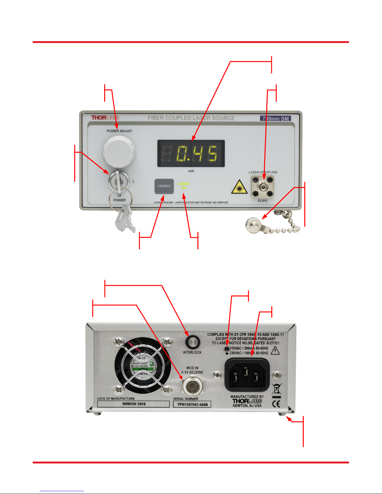
Chapter 5 Operation
3½ Digit Display
5.1. Front and Back Panel Overview
Power Adjust Knob
Keylock Power
Switch
Turn on power to
the unit. Key only
removes when off
Laser Aperture
FC/PC fiber optic connector
Laser Output
Cover
Cover should be
installed on FC
connector when
fiber removed
Laser Enable Switch
Press to activate laser
Remote Interlock Input
Modulation Input
0 to 5 V Max, 50 Ω
Laser Emission Indicator
Lights up 5 seconds before laser turns on
Voltage Type Cap Screw Indicator
AC Power Cord Connector
Figure 2 Front and Rear Panels of Laser Source
Page 6 2298-D11
Cover Screws (2)
Remove to access
line voltage switch
and fuse

Fiber-Coupled Laser Source Chapter 4: Setup
5.2. Turning On the Source
Turn the POWER key switch clockwise. The unit is ON when the display lights up.
Make sure the Interlock Input is short-circuited, see page 8 for more details..
Press and release the ENABLE switch to turn ON the laser. The LASER ON indicator will light up and
after a delay of approximately 5 seconds, the source will begin to emit light.
5.3. Adjusting the Laser Output Power
Use the PWR ADJUST knob to adjust the output power to the desired level.
The power shown on the display is the optical power at the laser aperture. The actual power at the end of
your fiber optic cable may be less, depending on the quality of the connection.
Note, each unit is calibrated internally to limit the maximum operating power of the laser diode to a safe operating
range.
5.4. Turning the Laser Off
The Laser output should be turned off by pressing and releasing the ENABLE switch.
When completely powering down an enabled unit, first press and release the ENABLE switch and then
turn the POWER key switch counterclockwise, which will turn OFF the entire unit. Anytime the unit is
turned OFF and then turned back ON, the Laser will be disabled until the ENABLE switch is pressed.
5.5. Modulating the Laser Output
The MOD IN input can be used to modulate the laser output, or set the laser output remotely using a +5 V power
source. The 5 V maximum input corresponds to the maximum calibrated power of the laser source. Each unit is
calibrated to achieve the maximum power for the particular laser diode used in the device. Due to variations in the
coupling process no two units will have the same maximum power.
Connect a signal generator or +5 V power source to the unit using a BNC type connector.
Set the PWR ADJUST knob to its full counter clockwise setting.
Press the ENABLE switch to turn on the laser.
Apply the appropriate signal to the MOD IN input. Signals above approximately 5.5 V will be clamped by
internal circuits.
Adjusting the PWR ADJUST knob will allow for a DC offset on the modulated output. Adjust the input
signal accordingly to avoid clipping the output waveform, which will occur if the unit is driven to its current
or power limits.
Caution!
DO NOT apply TTL or square wave modulation to the MOD IN input.
Due to response delays of the constant power control loop, damage to the integrated fiber
coupled laser may occur!
Rev T, June 7, 2018 Page 7

Fiber-Coupled Laser Source Chapter 6: Making the Safety Interlock Connections
Chapter 6 Making the Safety Interlock Connections
The S1 series laser sources are equipped with a remote interlock connector located on the rear panel, see Figure
2 on page 6. All units have this feature regardless of their FDA and IEC classifications. In order to enable the
laser source, a short circuit must be applied across the terminals of the Remote Interlock connector. In practice
this connection is made available to allow the user to connect a remote actuated switch to the connector (i.e. an
open door indicator). The switch (which must be normally open) has to be closed in order for the unit to be
enabled. Once the switch is in an open state the laser source will automatically shutdown. If the switch returns to
a closed condition the laser source must be re-enabled at the unit by pressing the ENABLE switch.
All units shipped from Thorlabs are configured with a shorting device installed in the Interlock connector. If you
are not going to use this feature then you can leave the shorting device installed and the unit will operate normally
as described in the procedures above.
If you wish to make use of the Interlock feature you will need to acquire the appropriate connector mate and wire
it your remote interlock switch. Next, remove the shorting device by pulling it out with a pair of needle nose pliers
and install the connector into the interlock input.
The interlock input only accepts a 2.5 mm mono phone jack. This connector is readily available at most
electronics stores.
The electrical specifications for the interlock input are shown in the following table.
Specification Value
Type of Mating Connector
Open Circuit Voltage
Short Circuit Current
Connector Polarity
Interlock Switch
Requirements
Figure 3 Remote Interlock Connector
2.5 mm Mono Phone Jack
+5 VDC with Respect to Chassis
Tip is +5 V, Barrel is Ground
Must be N.O. Dry Contacts
Under no circumstances should any
external voltages be applied to the
Ground
0.5 mA DC
Interlock input
Ground
+5 Volts
Page 8 2298-D11

Fiber-Coupled Laser Source Chapter 7: General Maintenance
Chapter 7 General Maintenance
Aside from the AC Input fuse there are no user serviceable parts in this product. If you suspect something has
failed on the unit, please contact Thorlabs for advice on returning the unit for evaluation.
7.1. Cleaning
The unit can be cleaned using a soft, slightly damp cloth. Avoid using any solvents on or near the unit.
7.2. Connector Cleaning
Always clean the ferrule end of your fiber patch cable prior to inserting it into the output FC Adapter. Your
benchtop source comes with a fiber-cleaning card (FCC-CLN4-1). This should be used before inserting the fiber
connector into the mating barrel.
Figure 4 Fiber Cleaning Card (FCC-CLN4-1)
To use the card, peel back and tear away one small blue strip. Holding the connector firmly, swipe the connector
tip across the exposed cleaning strip. The connector tip should be flush to the card surface for FC-PC connectors
and at a slight angle with the key straight up for FC-APC connectors.
Rev T, June 7, 2018 Page 9

Fiber-Coupled Laser Source Chapter 8: Specifications
Chapter 8 Specifications
Item # S1FC405 S1FC635 S1FC637 S1FC660 S1FC675 S1FC780
Wavelength
Min Full Output Power
Laser Class
Stability
Display Accuracy
Setpoint Resolution
Adjustment Range
Stability
Setpoint Accuracy
Setpoint Resolution
Adjustment Range
Operating Temp
405 nm 635 nm 637 nm 660 nm 675 nm 785 nm
8.0 mW 2.5 mW 8 mW 15.0 mW 2.5 mW 10 mW
3B 3R 3B 3B 3R 3B
15 min: ±0.05 dB, 24 hr: ±0.1 dB
(After 1 hr Warm-up at 25 ± 10 °C Ambient)
±10%
0.01 mW
~0 mW to Full Power
TEC
n/a
n/a
n/a
n/a
Environmental
15 to 35 °C
Storage Temp
AC Input
Modulation Input
Modulation Bandwidth
Fiber
S405-XP SM600 SM600 SM600 SM600 780HP
115 VAC / 230 VAC (Switch Selectable) 50 - 60 Hz
0 - 5 V = 0 - Full Power, DC or Sine Wave Input Only
5 kHz Full Depth of Modulation
30 kHz Small Signal Modulation
0 to 50 °C
Page 10 2298-D11

Fiber-Coupled Laser Source Chapter 8: Specifications
Item # S1FC785 S1FC808 S1FC980 S1FC1060 S1FC1310 S1FC1550
Wavelength
Min Full Output Power
Laser Class
Stability
Display Accuracy
Setpoint Resolution
Adjustment Range
TEC
Stability
Setpoint Accuracy
Setpoint Resolution
Adjustment Range
Environmental
Operating Temp
785 nm 808 nm 980 nm 1064 nm 1310 nm 1550 nm
20 mW 15.0 mW 13.0 mW 20.0 mW 1.5 mW 1.5 mW
3B 3B 3B 3B 1
15 min: ±0.05 dB, 24 hr:±0.1 dB
(After 1 hr Warm-up at 25 ± 10 °C Ambient)
±10%
0.1 mW 0.01 mW 0.1 mW 0.01 mW
~0 mW to Full Power
n/a
n/a
n/a
n/a
15 to 35 °C
Storage Temp
AC Input
Modulation Input
Modulation
Bandwidth
Fiber
0 to 50 °C
115 VAC / 230 VAC (Switch Selectable) 50 - 60 Hz
0 - 5 V = 0 - Full Power, DC or Sine Wave Input Only
5 kHz Full Depth of Modulation
30 kHz Small Signal Modulation
780HP SM800-5.6-125 SM980-5.8-125 HI1060 SMF-28-J9 SMF-28-J9
Rev T, June 7, 2018 Page 11

Fiber-Coupled Laser Source Chapter 9: Mechanical Drawing
Chapter 9 Mechanical Drawing
5.76"
(146.3 mm)
3.07"
(78.0 mm)
11.43"
(290.3 mm)
Figure 5 Mechanical Drawing
Page 12 2298-D11

Fiber-Coupled Laser Source Chapter 10: Regulatory
Chapter 10 Regulatory
As required by the WEEE (Waste Electrical and Electronic Equipment Directive) of the European Community and
the corresponding national laws, Thorlabs offers all end users in the EC the possibility to return “end of life” units
without incurring disposal charges.
This offer is valid for Thorlabs electrical and electronic equipment:
Sold after August 13, 2005
Marked correspondingly with the crossed out “wheelie bin” logo (see right)
Sold to a company or institute within the EC
Currently owned by a company or institute within the EC
Still complete, not disassembled and not contaminated
As the WEEE directive applies to self-contained operational electrical and electronic products, this end of life take
back service does not refer to other Thorlabs products, such as:
Pure OEM products, that means assemblies to be built into a unit by the user (e. g. OEM laser driver
cards)
Components
Mechanics and optics
Left over parts of units disassembled by the user (PCB’s, housings etc.).
If you wish to return a Thorlabs unit for waste recovery, please contact Thorlabs or your nearest dealer for further
information.
Wheelie Bin Logo
Waste Treatment is Your Own Responsibility
If you do not return an “end of life” unit to Thorlabs, you must hand it to a company specialized in waste recovery.
Do not dispose of the unit in a litter bin or at a public waste disposal site.
Ecological Background
It is well known that WEEE pollutes the environment by releasing toxic products during decomposition. The aim of
the European RoHS directive is to reduce the content of toxic substances in electronic products in the future.
The intent of the WEEE directive is to enforce the recycling of WEEE. A controlled recycling of end of life products
will thereby avoid negative impacts on the environment.
Rev T, June 7, 2018 Page 13

Fiber-Coupled Laser Source Chapter 11: Thorlabs Worldwide Contacts
Chapter 11 Thorlabs Worldwide Contacts
USA, Canada, and South America
Thorlabs, Inc.
56 Sparta Avenue
Newton, NJ 07860
USA
Tel: 973-300-3000
Fax: 973-300-3600
www.thorlabs.com
www.thorlabs.us (West Coast)
Email: sales@thorlabs.com
Support: techsupport@thorlabs.com
Europe
Thorlabs GmbH
Hans-Böckler-Str. 6
85221 Dachau
Germany
Tel: +49-(0)8131-5956-0
Fax: +49-(0)8131-5956-99
www.thorlabs.de
Email: europe@thorlabs.com
France
Thorlabs SAS
109, rue des Côtes
78600 Maisons-Laffitte
France
Tel: +33 (0) 970 444 844
Fax: +33 (0) 825 744 800
www.thorlabs.com
Email: sales.fr@thorlabs.com
Japan
Thorlabs Japan, Inc.
Higashi-Ikebukuro Q Building, 2F
2-23-2, Higashi-Ikebukuro,
Toshima-ku, Tokyo 170-0013
Japan
Tel: +81-3-5979-8889
Fax: +81-3-5979-7285
www.thorlabs.jp
Email: sales@thorlabs.jp
UK and Ireland
Thorlabs Ltd.
1 Saint Thomas Place, Ely
Cambridgeshire CB7 4EX
Great Britain
Tel: +44 (0)1353-654440
Fax: +44 (0)1353-654444
www.thorlabs.com
Email: sales.uk@thorlabs.com
Support: techsupport.uk@thorlabs.com
Scandinavia
Thorlabs Sweden AB
Bergfotsgatan 7
431 35 Mölndal
Sweden
Tel: +46-31-733-30-00
Fax: +46-31-703-40-45
www.thorlabs.com
Email: scandinavia@thorlabs.com
Brazil
Thorlabs Vendas de Fotônicos Ltda.
Rua Riachuelo, 171
São Carlos, SP 13560-110
Brazil
Tel: +55-16-3413 7062
Fax: +55-16-3413 7064
www.thorlabs.com
Email: brasil@thorlabs.com
China
Thorlabs China
Room A101, No. 100
Lane 2891, South Qilianshan Road
Putuo District
Shanghai
China
Tel: +86 (0) 21-60561122
Fax: +86 (0)21-32513480
www.thorlabschina.cn
Email: chinasales@thorlabs.com
Page 14 2298-D11

www.thorlabs.com
 Loading...