

Page 1
Operation Manual
Thorlabs Instrumentation
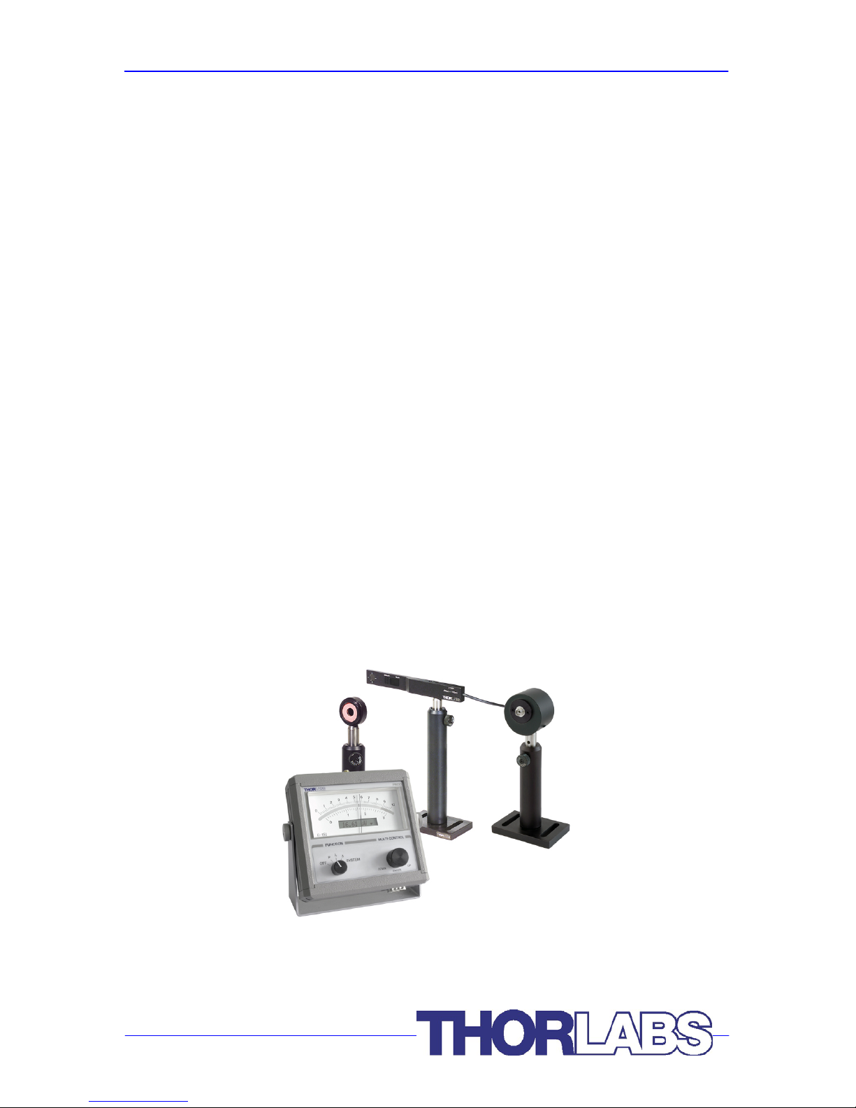
Optical Power Meter System
PM30-120, PM30-121, PM30-122
PM30-130, PM30-132
PM30-140, PM30-144
2006
Page 2

Version: 1.22 M0009-510-404
Date: 12.05.2006
Copyright© 2005, Thorlabs
Page 3

Contents Page
1 Safety 1
2 Description 3
2.1 Parts List – Accessories 3
2.2 Operating Elements 5
2.2.1 Front Panel 5
2.2.2 Top Panel 6
2.2.3 Bottom Panel 7
2.2.4 Rear Panel 7
2.2.5 Meter Stand 7
2.3 Operating Instruction 8
2.3.1 Battery Charging 8
2.3.2 Connecting the Optical Sensor 8
2.3.3 Switching on and off the PM30 8
2.3.4 Setting the Operating Wavelength 9
2.3.5 Measuring the Optical Power 9
2.3.6 Relative Measurement 10
2.3.7 System Menu 10
2.3.8 Photodiode adapter 10
2.4 Remote Control 11
2.5 Technical Data 19
2.5.1 PM30 Display Unit 19
2.5.2 S120B / S121B Silicon Sensor (PM30-120 / PM30-121) 20
2.5.3 S122B Germanium Sensor (PM30-122) 21
2.5.4 S130A / S132B Slim Sensor (PM30-130 / PM30-132) 22
2.5.5 S140A / S144A Integrating Sphere Sensor (PM30-140 / PM30-144) 23
3 Calibration and Warranty 24
3.1 Calibration 24
3.2 Warranty 24
4 Service and maintenance 26
4.1 General Care 26
4.2 Cleaning 27
4.3 Line Voltage 27
4.4 Repair 27
4.5 Certifications and Compliances 28
4.6 Thorlabs “End of Life” policy (WEEE) 29
4.6.1 Waste treatment on your own responsibility 29
4.6.2 Ecological background 30
4.7 Addresses 31
Page 4

We aim to develop and produce the best solution for your application in the
field of optical measurement technique. To help us to come up to your
expectations and develop our products permanently we need your ideas and
suggestions. Therefore, please let us know about possible criticism or ideas.
We and our international partners are looking forward to hearing from you.
Thorlabs
Attention
This manual contains “WARNINGS” and “ATTENTION” label in this
form, to indicate danger for persons or possible damage of equip-
ment.
Please read these advises carefully!
NOTE
This manual also contains “NOTES” and “HINTS” written in this form.
Page 5

2.1 Parts List – Accessories
PM30 / page 1
1 Safety
Attention
All statements regarding safety of operation and technical data in
this instruction manual will only apply when the unit is operated
correctly.
Use only the power cord specified for the unit.
Do not operate the power meter if its panels are removed or any of
the interior circuitry is exposed
Do not operate the power meter in wet or damp conditions, or in an
explosive atmosphere.
Operate the power meter only within the specified voltage range
Do not apply voltage outside the specified range of the input connec-
tions
Do not operate the power meter if there are suspected failures. Refer
damaged units to qualified Thorlabs service personnel
Page 6

2.1 Parts List – Accessories
PM30 / page 2
Attention
This equipment has been tested and found to comply with the limits
for a Class A digital device, pursuant to part 15 of the FCC Rules.
These limits are designed to provide reasonable protection against
harmful interference when the equipment is operated in a commer-
cial environment. This equipment generates, uses, and can radiate
radio frequency energy and, if not installed and used in accordance
with the instruction manual, may cause harmful interference to radio
communications. Operation of this equipment in a residential area is
likely to cause harmful interference in which case the user will be
required to correct the interference at his own expense.
Standard shielding and filtering measures have to be undertaken to
avoid interferences with other electronic equipment!
NOTE
Please check prior to operation, if the line voltage range, indicated on the
power supply agrees with your local supply
Page 7

2.1 Parts List – Accessories
PM30 / page 3
2 Description
The Thorlabs PM30 Power Meter system is an easy to use, flexible optical power
measurement system with optical sensor. Its mechanical analog needle display
features best readability and real time response for fast laser tuning. The additional
digital display allows accurate power readings and a convenient system setup.
The Thorlabs’ optical power meter sensors feature NIST traceable wavelength
calibration over the specified wavelength range. Please refer to www.thorlabs.com
for new sensors that will enhance the PM30 system.
The console is powered by a 6V, 150mAh nickel-metal-hybrid (NiMH) battery for long
life operation and fast recharging times. The included external power supply is
provided to recharge the battery pack as well as to operate the unit.
2.1 Parts List – Accessories
The power meter system consists of the following items:
• PM30 power meter console
• Operation manual
• PMPS12 Power supply (12V, 0.85A), 90 .. 264V line voltage,
line adaptors for US, EU, UK.
Depending on the order code the power meter system comes with one of the sensors
given below:
PM30-120: S120B – Silicon Sensor Power Head; 50nW – 50mW
400 – 1100nm
PM30-121: S121B – Silicon Sensor Power Head; 500nW – 500mW;
400 – 1100nm
PM30-122: S122B – Germanium Sensor Power Head; 35nW – 35mW;
700 – 1800nm
PM30-130: S130A – Slim, dual range Silicon Sensor Power Head;
5nW – 500mW; 400 – 1100nm
Page 8

2.1 Parts List – Accessories
PM30 / page 4
PM30-132: S130A – Slim, dual range Germanium Sensor Power Head;
5nW – 500mW; 400 – 1100nm
PM30-140: S140A – Integrating Sphere Silicon Sensor Power Head;
1µW – 1W; 400 – 1100nm
PM30-144: S144A – Integrating Sphere InGaAs Sensor Power Head;
1µW – 1W; 800 – 1700nm
When unpacking the PM30 system the first time, please check if all items are present
and in good condition. If any items are missing or damaged please advise Thorlabs
immediately for issuing a Returned Material Authorization (RMA) for this instrument.
Page 9
2.2 Operating Elements
PM30 / page 5
2.2 Operating Elements
2.2.1 Front Panel
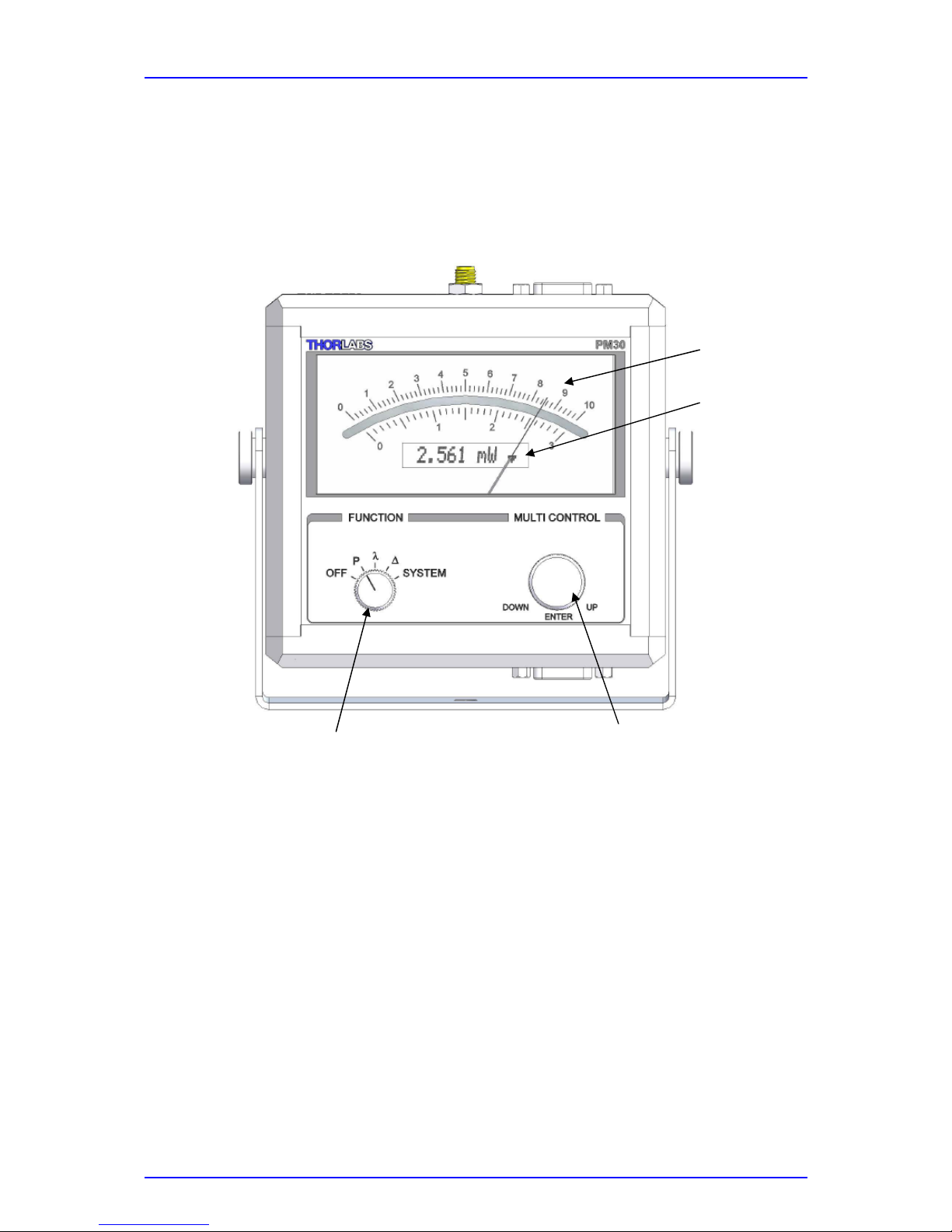
Figure 1 PM30 Front Panel
Analog Meter Shows the measured power level on the scale that
corresponds to the selected power range. An up showing
arrow in the digital display indicates that the 10-division
scale is used, a down-showing arrow indicates the 3division scale.
LC Display The 12 digit LCD allows precise power measurements
along with additional system information and input capabilities. The LCD can be backlit in two brightness settings in
the system menu.
Analog Meter
Control Switch
Main Switch
LC Display
The Arrow
indicates that the
3-division scale is
used
Page 10
2.2 Operating Elements
PM30 / page 6
Main Switch The main switch powers on and off the unit and selects the
power measurement, wavelength setting, zeroing and system menus.
Control Switch The control switch is used to set power range, correction
wavelength as well as controlling and viewing system settings. The switch has turning and push button functionality.
2.2.2 Top Panel
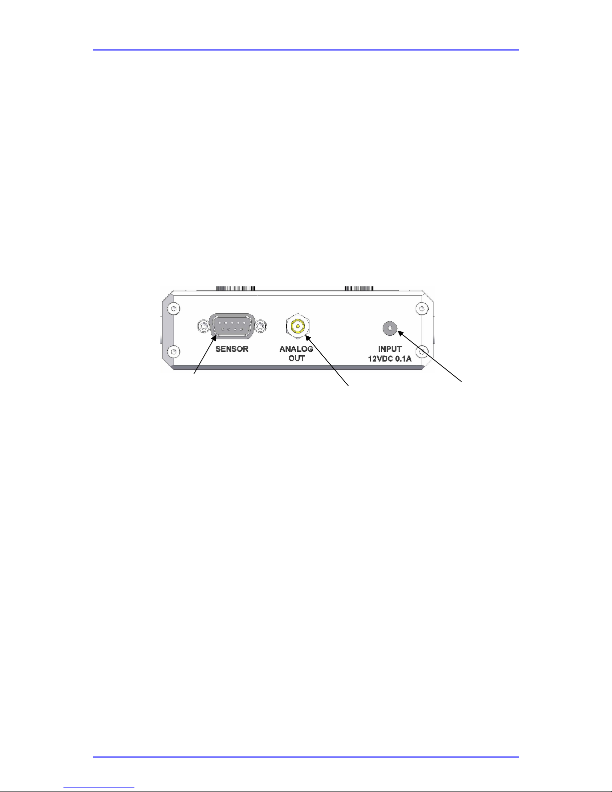
Figure 2 PM30 Top Panel
DB9 Sensor Jack All Thorlabs S1xxX series optical detectors and the PM30
photodiode adapter can be plugged to this connector.
Analog Output The SMA connector outputs a voltage from 0.0 to 1.0V
corresponding to the selected power range.
Charger Input To charge the battery plug-in the 12VDC power supply that
ships with the instrument. The batteries will recharge within
2.5 hours.
DB9 Sensor Jack
SMA Analog
Output Jack
Charger
Input Jack
Page 11
2.2 Operating Elements
PM30 / page 7
2.2.3 Bottom Panel
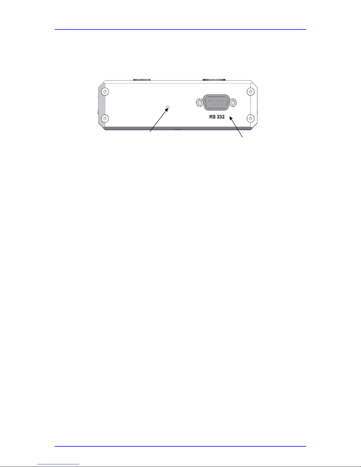
Figure 3 PM30 Bottom Panel
DB9 RS232 Interface Operates the meter in remote control via serial interface
with a fixed baudrate of 9600 bit/s
Program button Enables Software Updates via the serial interface
2.2.4 Rear Panel
Meter Zero Adjust Is used to adjust the mechanical offset of the meter to zero.
This value is factory set but may need readjustment after
mechanical shock.
The unit must be turned off and put in the standard viewing
position before zeroing the meter.
2.2.5 Meter Stand
The unit comes with a pivoting stand that allows to continuously adjust the meter to
the ideal viewing position.
Serial Interface Connector
Service Push Button
Page 12

2.3 Operating Instruction
PM30 / page 8
2.3 Operating Instruction
2.3.1 Battery Charging
The PM30 has a built in NiMH rechargeable battery for an operation up to 50hrs
(without backlight). When the batteries need recharging an empty battery sign
appears on the right side of the digital display.
The batteries are not fully charged when shipping. A battery that is new or has not
been used for a longer period does not develop its full capacity until after
approximately 2.5 hours of charging.
Plug the in the delivery included 12DC power supply to the input connector in the top
panel and the power supply into a suitable AC outlet. Attach the right adapter
depending on local power requirements to the power supply, adapters for US, Europe
and UK are provided with the instrument. If the adapter is lost, contact Thorlabs for
replacement.
When the charger is plugged a filled battery sign in the LC display indicates that the
charger works in “full-charge” mode, the charging circuit goes automatically in
“trickle-charge” mode when the batteries are fully charged. In this case the indicator
in the LCD changes to a wall-plug sign.
Do not exceed the line voltage that is stated on the power supply. The power supply
gets warm after longer time of use; this is normal and not dangerous.
The unit can be operated normally while the 12VDC adapter is plugged in.
2.3.2 Connecting the Optical Sensor
Plug the DB-9 connector of the optical head into the jack located on the top of the
console and secure the two screws. Thorlabs S1xxX Sensors can be plugged or
changed while the power meter is switched on. The display unit will automatically
recognize the sensor and work with the appropriate calibration data, that are
downloaded from the non-volatile memory in the sensor connector.
2.3.3 Switching on and off the PM30
If the unit is not already switched on, turn the main switch from the OFF position, the
PM30 will power up and show the connected sensor data and for approximately 3
seconds the set wavelength. The unit will stay on until the selected auto-shutdown
time that can be set in the system menu is reached. After this time the PM30 will
Page 13

2.3 Operating Instruction
PM30 / page 9
automatically switch of for battery saving. To power up the unit again the rotary
switch has to be put to the OFF position and then back to one operating position, the
unit will continue measuring with the set conditions prior to shut-off.
To manually shut down the PM30 turn the main switch to the OFF position. All
system and measurement settings will be present when turning the unit on again. To
keep set values the unit must be on for a minimum of 10 seconds after changing the
set value.
2.3.4 Setting the Operating Wavelength
Turn the left rotary switch into the λ-position, the digital display will show a
wavelength in nm. Click on the control button to enter the wavelength set menu, by
each click a digit of the set wavelength will get underlined. By turning the control
button each digit can be scrolled up and down in the sensor wavelength range. The
set values are immediately used for the power calculation. To leave the menu turn
the main switch back to the P-position. After 10s the wavelength set value will be
stored in the PM30 console and is present after shutting off and on the unit (when
using the same type of sensor!).
The minimum and maximum settable wavelength is sensor dependent and
downloaded to the instrument when connecting the sensor.
2.3.5 Measuring the Optical Power
Turn the unit into the P-position, place the sensor in the path of the laser beam,
conduct one-time auto-ranging by clicking the control button, or select a power range
manually by turning the control button, and read the optical power on the range
corresponding scale or in the digital display.
The PM30 usually works in manual-range mode. The power ranges can be set in x3,
x10 steps, after setting the current power range is indicated for approx. 1s in the LC
display. After this time the LCD switches back to the power reading, that includes the
power units and the corresponding scale of the analog meter.
The minimum and maximum settable power range is sensor dependent and
downloaded to the instrument when connecting the sensor.
Attention
Refer to the sensor data sheet and pay attention to the optical
damage threshold!
Exceeding these values will permanently destroy the sensor!
Page 14

2.3 Operating Instruction
PM30 / page 10
2.3.6 Relative Measurement
This feature can be used either for backlight subtraction or performing a relative
measurement.
Turn the unit into the ∆-position. Click the control button to subtract the current
reading. The digital display shows the subtracted power reading, the analog needle
goes to zero.
Turn the main switch back in the P position. The digital display now shows the
difference to the subtracted reading followed by a ∆ sign. Power ranges can be set
only in the Up position.
2.3.7 System Menu
To enter the system menu turn the main switch to the SYSTEM position. The system
menu allows the following settings / contains the following information:
The menu can be navigated by turning the control button. Submenus are entered by
clicking the control button.
Shutdown: Sets the time after that the unit automatically switches off.
5 minutes / 1 hour / never
Backlight: Turns the LCD backlight on and allows two brightness settings.
Powersaving / ON / OFF
System SN: Shows the serial number of the device.
Version: Displays the firmware version
Sensor Name: Displays the type of the connected sensor
Sensor SN: Shows the serial number of the connected sensor
2.3.8 Photodiode adapter
Instead of a calibrated power meter sensor the optional available photodiode adapter
PM30PDA allows to use the PM30 as a current and power display for any floating or
anode grounded photodiodes with a photo current up to 4mA.
Plug the adapter on the PM30 sensor connector input and tighten the fixing screws.
The photodiode cathode has to be connected to the center, the anode to the shield of
the adapter’s SMA input connector.
The operation is similar to the standard operation. Instead of the wavelength a
responsivity value can be set to perform a single point power calibration. The setting
Page 15
0
PM30 / page 11
range is 1mA/W to 99999 mA/W. The default responsivity value is 1000 mA/W, so
the power reading will correspond directly to a current reading in A.
Refer to www.thorlabs.com for directly connectable anode grounded photodiodes
from the type SM05PD and SM1PD and for suitable SMA connection cables.
2.4 Remote Control
The PM30 has a built in serial interface to operate the unit remotely or upload new
firmware.
It is not possible to change device settings locally while the device is in remote
operating mode. If the Interface is connected and active, the device will not shutdown
automatically regardless of the Shutdown setting.
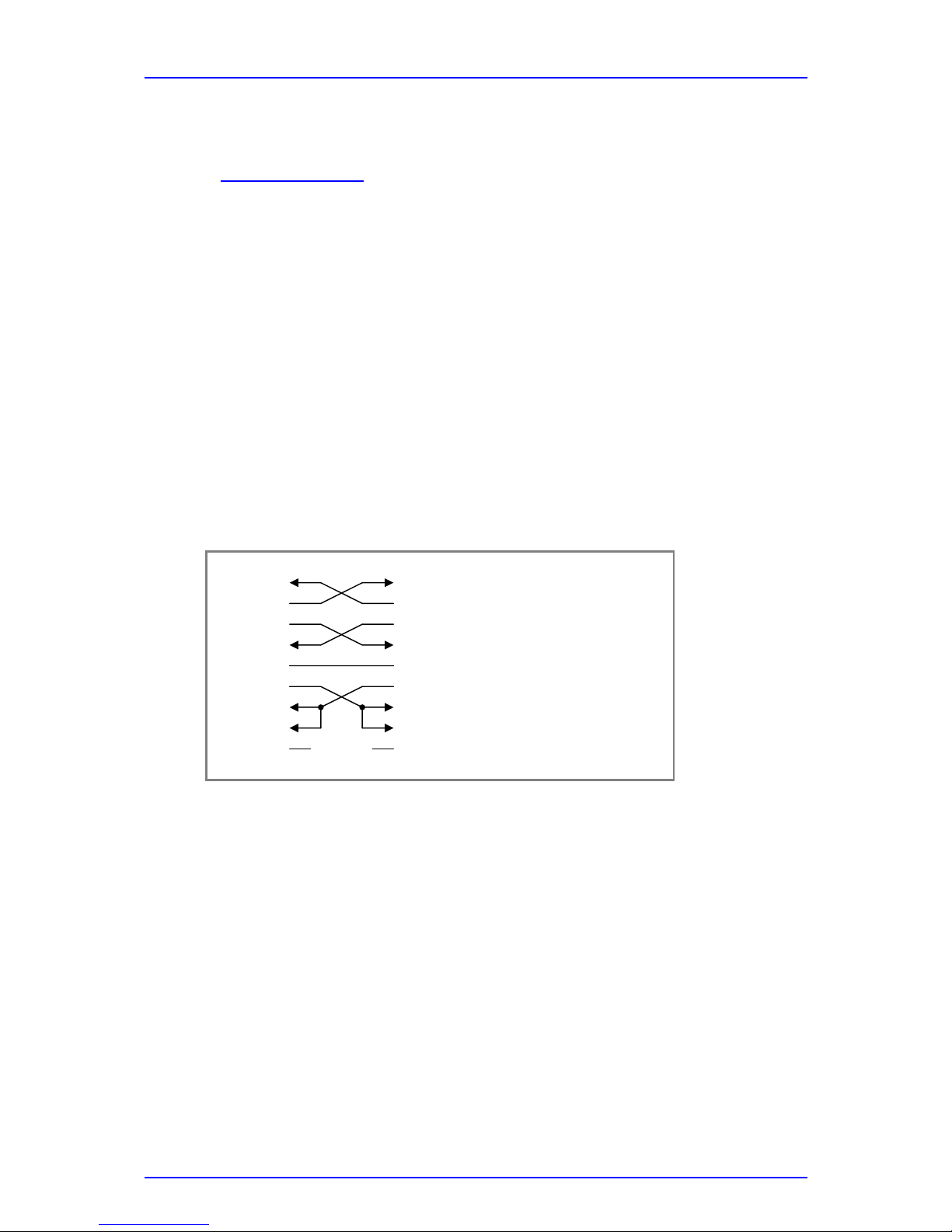
The device is considered to be a Data Terminal Equipment (DTE). To connect it with
a control PC use a 9 pole null-modem cable which is connected like shown in the
following figure.
Set up your control PC to meet the following communication setup:
Line setup: 9600-8N1-RFR/CTS
(8 data bits, 1 stop bit, no parity)
Program message end character: <LF>
(Line Feed, 0A
hex
)
Response message end characters: <CR><LF>
(Carriage Return, 0D
hex;
Line Feed, 0A
hex
)
The device will switch to remote operation mode after recognition of the first valid
command sent to the device. It will switch back to local operation mode by receiving
Receive Data
Ready for receiving
Clear to send
Signal Ground
Data terminal ready
Receiver Line Signal Detection
Data set ready
2 RXD
3 TXD
7 RFR
8 CTS
5 GND
4 DTR
1 RLSD
6 DSR
9 RI Ring Indicator
2 RXD
3 TXD
7 RFR
8 CTS
5 GND
4 DTR
1 RLSD
6 DSR
9 RI
Page 16
2.4 Remote Control
PM30 / page 12
the ‘>L’ emulation code (see below) or by disconnecting the cable connection
(DSR/DTR circuit).
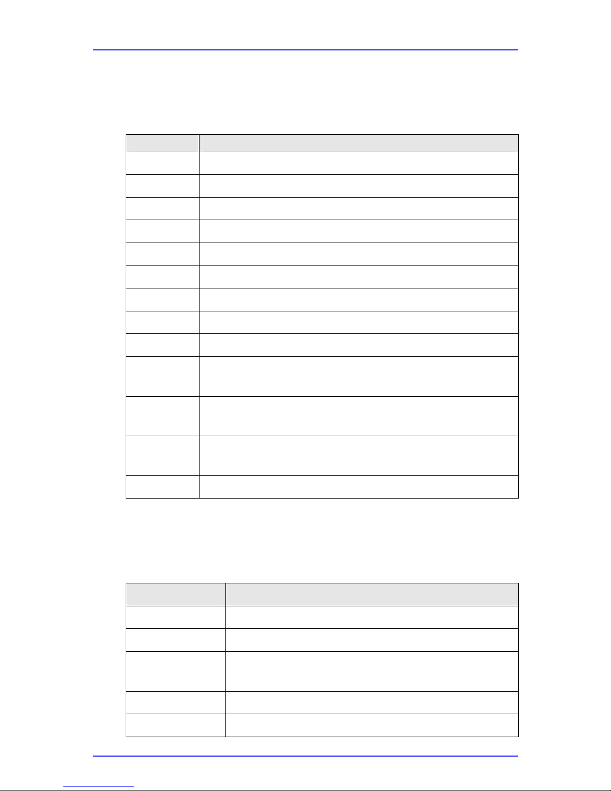
IEEE488.2 Common Commands:
Command Description
*IDN?
Identification query. (IEEE488.2-1992-§10.14)
*TST?
Self test query. (IEEE488.2-1992-§10.38)
*OPC
Operation complete command. (IEEE488.2-1992-§10.18)
*OPC?
Operation complete query. (IEEE488.2-1992-§10.19)
*WAI
Wait command. (IEEE488.2-1992-§10.39)
*RST
Reset command. (IEEE488.2-1992-§10.32)
*SRE
Service Request Enable command. (IEEE488.2-1992-§10.34)
*SRE?
Service Request Enable query. (IEEE488.2-1992-§10.35)
*STB?
Read Status Byte query. (IEEE488.2-1992-§10.36)
*ESE
Standard Event Status Enable command. (IEEE488.2-1992-
§10.10)
*ESE?
Standard Event Status Enable query. (IEEE488.2-1992-
§10.11)
*ESR?
Standard Event Status Register query. (IEEE488.2-1992-
§10.12)
*CLS
Clear Status command. (IEEE488.2-1992-§10.3)
Device Specific Commands:
Command Description
:POWER?
Query the last measured power value [Watt]
:WAVELENGTH?
Query the currently used wavelength [m]
:WAVELENGTH
Set the wavelength [m] to use for calculating the
sensitivity
:PDRESP?
Query the currently used responsivity [A/W]
:PDRESP
Set the responsivity [A/W]
Page 17

2.4 Remote Control
PM30 / page 13
:RANGE?
Query the measurement range.
:RANGE
Set the measurement range.
:OFFSET?
Query the currently used zero offset [W].
:OFFSET
Set the zero offset value [W].
:SENS:TYPE?
Query the optical sensor’s type.
:SENS:NAME?
Query the optical sensor’s name.
:SENS:SERNR?
Query the optical sensor’s serial number.
:SENS:RANGE?
Query the optical sensor’s range data.
:SYST:ERR?
Query the device’s error queue.
Power Query
Command syntax:
:POWER?
Response syntax:
last measured power <NR3 NUMERIC RESPONSE DATA>
Prerequisite: None
Description: Queries the last measured absolute power value [Watt].
Note: If a A/D converter overflow occurs the value 2.0e+6 is returned.
Note: There is the absolute Power value returned. A zero offset value
does not affect this value. (See also ‘Set Zero Offset’ command)
Wavelength Query
Command syntax:
:WAVELENGTH?
Response syntax:
Currently used wavelength <NR3 NUMERIC RESPONSE DATA>
Prerequisite: There must be a calibrated sensor connected.
Description: Queries the currently used wavelength [m].
Page 18

2.4 Remote Control
PM30 / page 14
Set Wavelength Command
Command syntax:
:WAVELENGTH <DECIMAL NUMERIC PROGRAM DATA>
Prerequisite: There must be a calibrated sensor connected.
Description: Set the wavelength [m] to use for calculating the sensitivity. The
resolution is 1.0nm.
Note: The wavelength range depends on the connected sensor.
Photo Diode Responsivity Query
Command syntax:
:PDRESP?
Response syntax:
currently used photo diode responsivity
<
NR3 NUMERIC RESPONSE
DATA>
Prerequisite: None
Description: Queries the currently used photo diode responsivity [A/W].
Set Photo Diode Responsivity Command
Command syntax:
:PDRESP <DECIMAL NUMERIC PROGRAM DATA>
Prerequisite: There must be a photo diode adaptor connected to the device.
Description: Set the photodiode responsivity [A/W]. The photo diode responsivity
must be in the range from 0.001A/W to 10.0A/W. The resolution is
0.001A/W.
Page 19

2.4 Remote Control
PM30 / page 15
Measurement Range Query
Command syntax:
:RANGE?
Response syntax:
currently used measurement range
<
NR1 NUMERIC RESPONSE
DATA>
Prerequisite: None
Description: Queries the measurement range. For details see ‘Set Measusement
Range’.
Set Measurement Range
Syntax:
:RANGE <DECIMAL NUMERIC PROGRAM DATA>
Prerequisite: There must be a sensor/adaptor connected.
Description: Sets the measurement range according to the following table:
Value Measurement Range Value Measurement Range
0 100nW 8 1mW
1 300nW 9 3mW
2 1µW 10 10mW
3 3µW 11 30mW
4 10µW 12 100mW
5 30µW 13 300mW
6 100µW 14 1W
7 300µW
Note: The minimum settable range value depends on the connected
sensor and the wavelength value (the selected responsivity). The
maximum settable range value depends on the connected sensor.
Zero Offset Query
Command syntax:
:OFFSET?
Response syntax:
currently used zero offset value [W]
<
NR3 NUMERIC RESPONSE
DATA>
Prerequisite: None
Description: Queries the currently used zero offset value [W].
Page 20

2.4 Remote Control
PM30 / page 16
Set Zero Offset Command
Command syntax:
:OFFSET <DECIMAL NUMERIC PROGRAM DATA>
Prerequisite: None
Description: Sets the zero offset value [W].
Note: The maximum settable value is the fullscale value of the selected
measurement range. Setting the zero offset value may also switch the
selected measurement range. The power value read by the power
query command will not be affected by the zero offset value.
Optical Sensor Type/ID Query
Command syntax:
:SENS:TYPE?
Response syntax:
Sensor-Type/ID <HEXADECIMAL NUMERIC RESPONSE DATA>
Prerequisite: None
Description: Queries the sensor type and ID.
Value
(hex)
Sensor
0000 Photo diode adaptor
0101 S120A Silicon Sensor
0201 S122A Germanium Sensor
NN11 Generic Sensor (NN = Sensor specific ID)
FFFF No Sensor connected
Note: If there is no sensor connected an error will be placed into the
device’s error queue.
Optical Sensor Name Query
Command syntax:
:SENS:NAME?
Response syntax:
Sensor name <STRING RESPONSE DATA>
Prerequisite: None
Description: Queries the name of the connected optical sensor.
Note: If there is no sensor connected an error will be placed into the
device’s error queue.
Page 21

2.4 Remote Control
PM30 / page 17
Optical Sensor Serial Number Query
Command syntax:
:SENS:SERNR?
Response syntax:
sensor’s serial number <STRING RESPONSE DATA>
Prerequisite: None
Description: Queries the serial number of the connected optical sensor.
Note: If there is no sensor connected an error will be placed into the
device’s error queue.
Page 22

2.4 Remote Control
PM30 / page 18
Optical Sensor Range Query
Command Syntax
:SENS:RANGE?
Response syntax:
Minimum wavelength [m] <NR3 NUMERIC RESPONSE DATA> ,
Maximum wavelength [m] <NR3 NUMERIC RESPONSE DATA> ,
Minimum power [W] <NR3 NUMERIC RESPONSE DATA> ,
Maximum power [W] <NR3 NUMERIC RESPONSE DATA>
Prerequisite: None
Description: Queries the optical sensor head wavelength and power ranges.
Note: If there is no sensor connected an error will be placed into the
device’s error queue.
Error Query
Command syntax:
:SYST:ERR?
Response
syntax:
Error number <NR1 NUMERIC RESPONSE DATA> ,
Error text <ARBITRARY ASCII RESPONSE DATA>
Prerequisite: None
Description: Queries the device’s error queue (see also: Chapter ‘Error Reporting’ in
this document).
Page 23

2.5 Technical Data
PM30 / page 19
2.5 Technical Data
(All technical data are valid at 23 ± 5°C and 45 ±15% humidity)
2.5.1 PM30 Display Unit
General
Dimensions (H x W x D) 120 x 112 x 45 mm³
(4.7” x 4.4” x 1.8”)
135 x 143 x 45 mm³ with stand
(5.3” x 5.6” x 1.8”)
Weight 0.6 kg 1.33 lbs
Operating Temperature 5°C – 40°C
Storage Temperature -20°C – 70°C
Meter Specifications
Measurement Range 1nW to 1W
Power Scales Up to 15 sensor-
dependent scales
100nW, 300nW, 1µW, 3µW,
10µW, 30µW, 100µW, 300µW,
1mW, 3mW, 10mW, 30mW,
100mW, 300mW, 1W
Power Resolution 0.1nW / 14 bit Digital Display
Power Units nW, µW, mW, W
Digital Display 12 digit alphanumerical With backlight
Accuracy Digital Display +/- 1%
Analog Meter 90 x 42 mm (3.54” x 1.65”)
Accuracy Analog Meter +/- 3%
Meter Scales 0 to 3 (30 divisions)
0 to 10 (50 divisions)
Mirrored Scale
Analog Output 0 to 1V Corresponding to Range
Setting
Accuracy Analog Output +/- 1%
Power Supply
Battery Operation 6V built-in
rechargeable battery
Battery charger included
Auto Shutdown (detachable)
Low Battery indicator Annunciation in LCD Battery voltage < 5.5V
Battery Life time 50 hrs / 15 hrs Without / With backlight
AC Operation 90 to 260V 50/60Hz
12VDC isolated adaptor
Included
Charging time 2.5 hrs to full charge
Safety
CE compliant
Page 24
2.5 Technical Data
PM30 / page 20
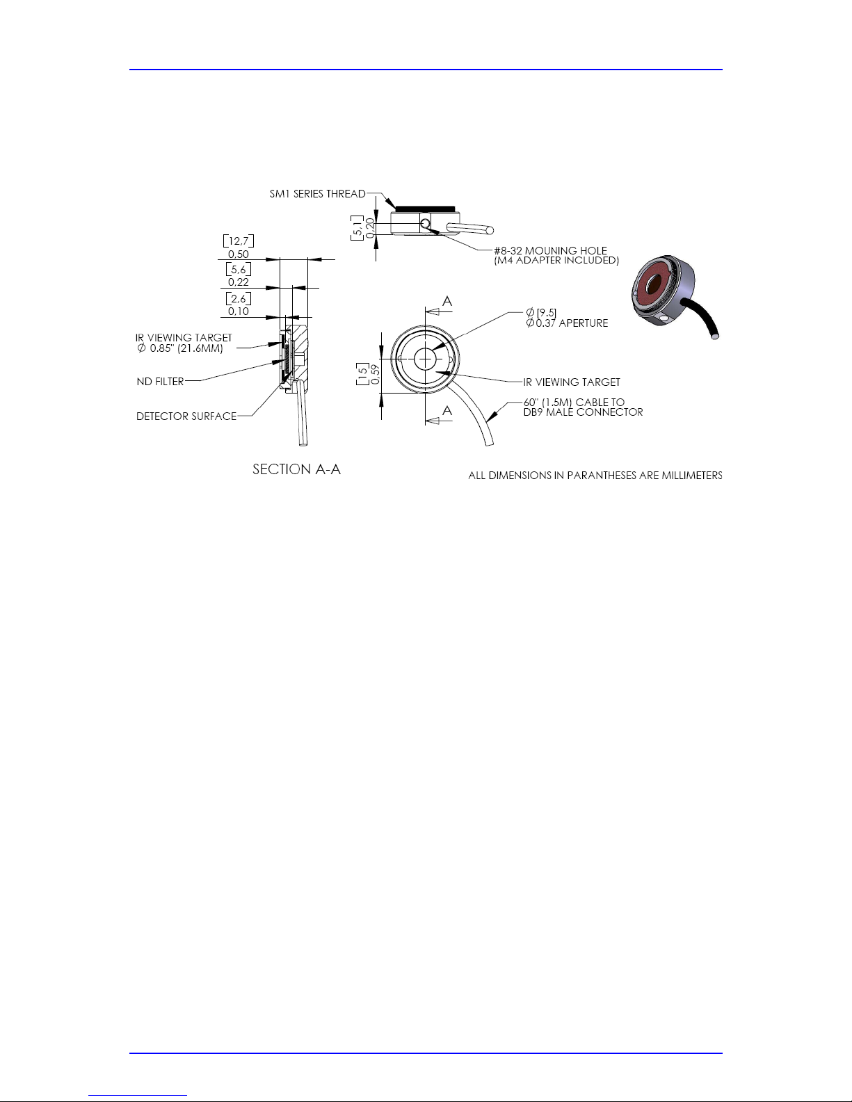
2.5.2 S120B / S121B Silicon Sensor (PM30-120 / PM30-121)
Mechanical Drawing:
Specifications:
Spectral range: 400 – 1100nm
Sensor: Silicon
Sensor size: 10mm x 10mm sq. (0.39” x 0.39”)
Input aperture: ∅ 9.5mm (0.374”)
Distance to ND filter: 2.6mm (0.1”)
Distance to detector: 5.6mm (0.22”)
Aperture thread 1.035-40 Outer Thread (SM1 compatible)
Optical power range: S120B: 50nW – 50mW (@ 980nm)
S121B: 500nW – 500mW (@ 980nm)
Resolution: 100pW (S120B)/ 1nW (S121B)
Optical Damage Threshold: 50W/cm²
Measurement Standard: NIST traceable
Measurement uncertainty: +/- 5%
Operating temperature: 5°C to 40°C
Weight: 0.07kg (0.155lbs)
Notes:
The sensor contains an IR viewing target with absorption bands from 400 to 640nm
and 800 to 1700nm that can be removed by carefully levering in the side hole with a
small screw driver.
The sensors can be equipped with fiber adapters from the S120 series.
(Order Codes: S120-FC, S120-SMA, S120-SC)
For use with metric posts insert the 8-32 to M4 adapter.
Page 25
2.5 Technical Data
PM30 / page 21
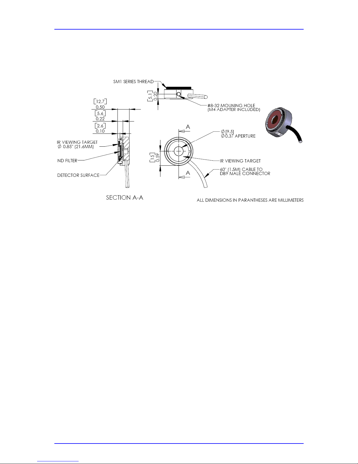
2.5.3 S122B Germanium Sensor (PM30-122)
Mechanical Drawing:
Specifications:
Spectral range: 700 – 1800nm
Sensor: Germanium
Sensor size: 10mm x 10mm sq. (0.39” x 0.39”)
Input aperture: ∅ 9.5mm (0.374”)
Distance to ND filter: 2.6mm (0.10”)
Distance to detector: 5.6mm (0.22”)
Aperture thread 1.035-40 Outer Thread (SM1 compatible)
Optica l power range: 35nW – 35mW (@ 1550nm)
Resolution: 100pW
Measurement Standard: NIST traceable
Measurement uncertainty: +/- 5%
Operating temperature: 5°C to 40°C
Weight: 0.07kg (0.155lbs)
Notes:
The sensor contains an IR viewing target with absorption bands from 400 to 640nm
and 800 to 1700nm that can be removed by carefully levering in the side hole with a
small screw driver.
The sensor can be equipped with fiber adapters from the S120 series.
(Order Codes: S120-FC, S120-SMA, S120-SC)
For use with metric posts insert the 8-32 to M4 adapter.
Page 26
2.5 Technical Data
PM30 / page 22
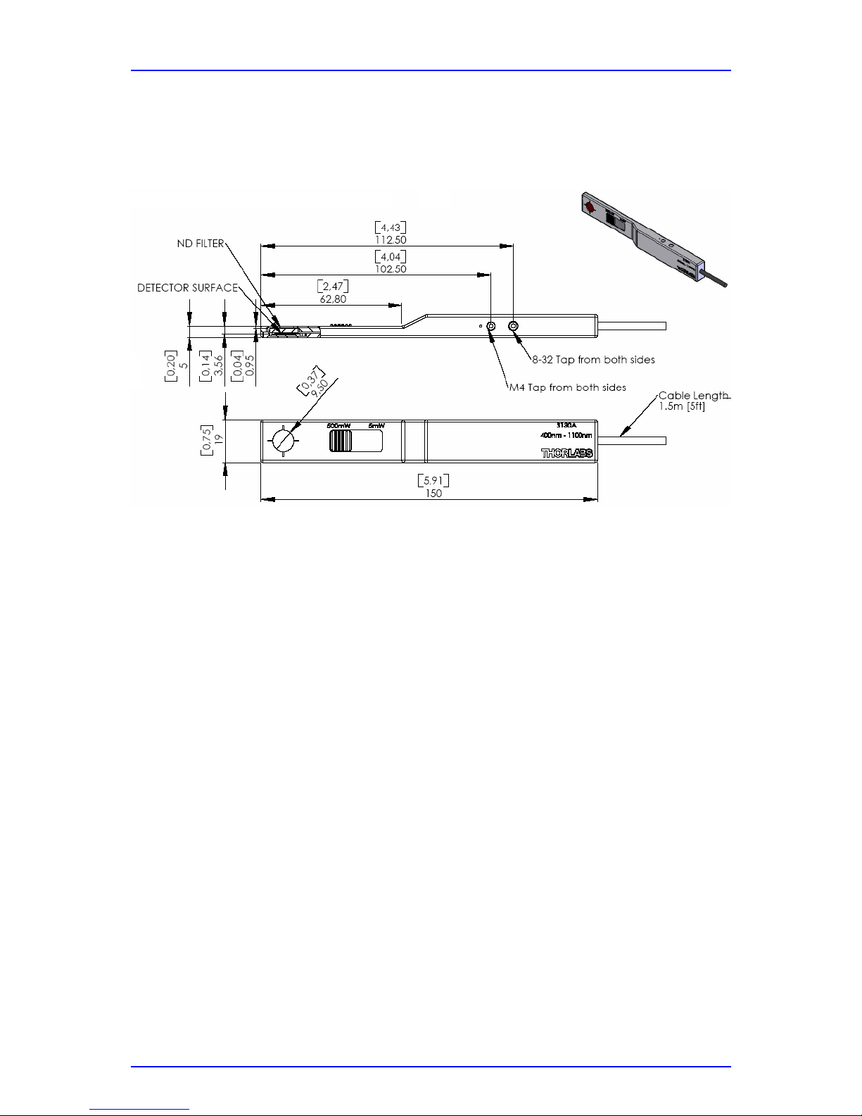
2.5.4 S130A / S132B Slim Sensor (PM30-130 / PM30-132)
Mechanical Drawing:
Specifications: S130A S132A
Spectral range: 400 – 1100nm | 700 – 1800nm
Sensor: Silicon | Germanium
Sensor size: 10mm x 10mm sq. (0.39” x 0.39”)
Input aperture: ∅ 9.5mm (0.374”)
Distance to ND filter: 3.3mm (0.12”)
Distance to detector: 5.8mm (0.23”)
Optical power range (@980nm): 5nW – 5mW
5µW – 500mW | (50mW @1550nm)
Resolution: 100pW
Optical Damage Threshold: 50W/cm²
Measurement Standard: NIST traceable
Measurement uncertainty: +/- 5%
Operating temperature: 5°C to 40°C
Weight: 0.125kg (0.155lbs)
Notes:
The sensor contains two sets of calibration data for both slider positions. The console
automatically uses the right calibration data a few seconds after the slider has been
moved. Please care that the slider is always in a “snapped” position.
Page 27
2.5 Technical Data
PM30 / page 23
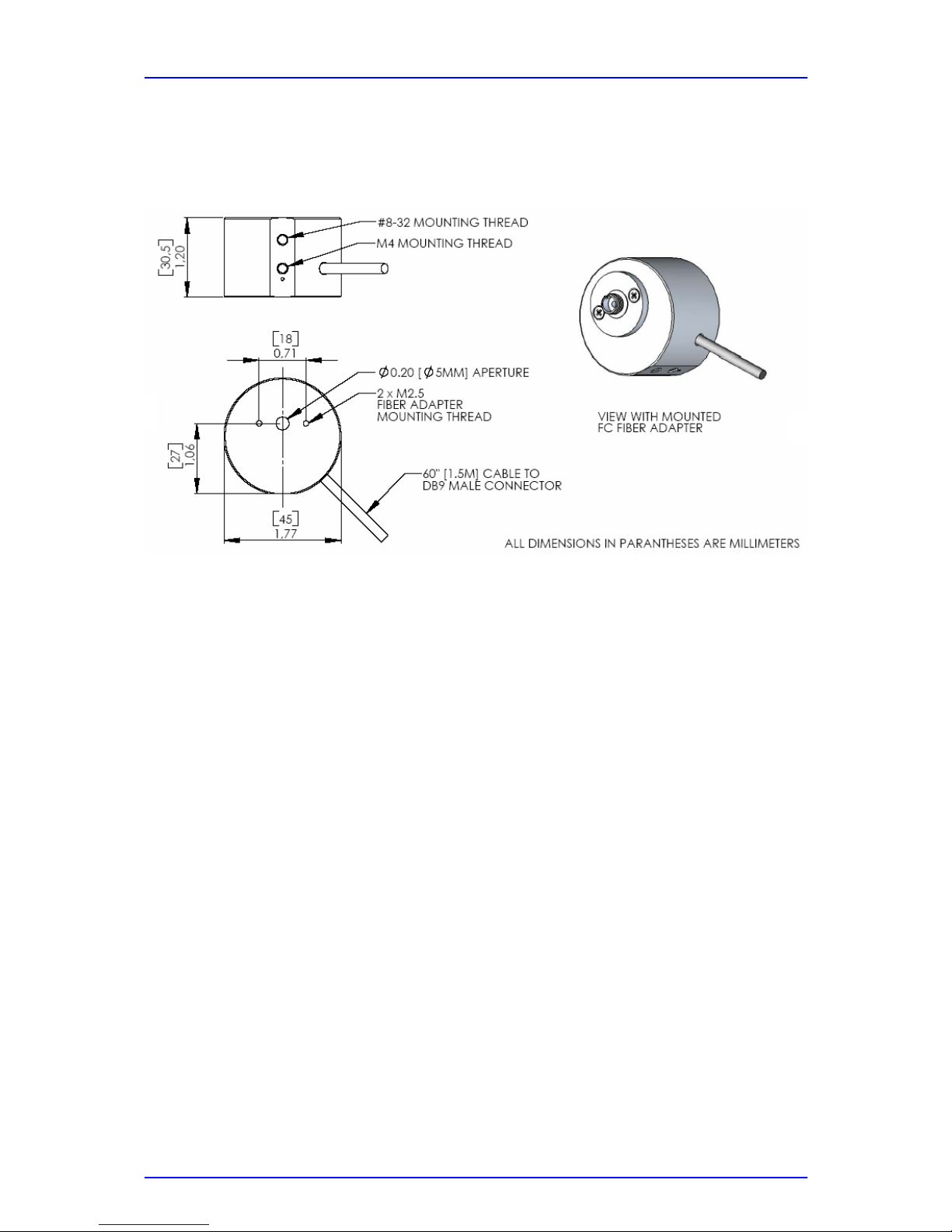
2.5.5 S140A / S144A Integrating Sphere Sensor (PM30-140 / PM30-144)
Mechanical Drawing:
Specifications: S140A S144A
Spectral range: 400 – 1100nm | 800 – 1700nm
Sensor: Silicon | InGaAs
Measurement Principle: Integrating Sphere
Sensor size: ∅ 1mm
Input aperture: ∅ 5mm (0.20”)
Optical power range 1µW – 1W
Resolution: 10nW
Optical Damage Threshold: 200W/cm²
Measurement Standard: NIST traceable
Measurement uncertainty: +/- 5%
Operating temperature: 5°C to 40°C
Weight: 0.125kg (0.155lbs)
Notes:
To remove or change the fiber adapter, loosen the two M2.5x4 screws and lift-off the
adapter. Fiber adapters are available for SMA connectors (S140-SMA) and SC
connectors (S140-SC).
Without fiber adapter the sensor can be used in free-space applications.
Page 28

3.1 Calibration
PM30 / page 24
3 Calibration and Warranty
3.1 Calibration
Thorlabs optical power meters and sensors are precise instruments that are designed
to deliver very accurate measurements and provide useful service over a long period
of time. For maintaining this high level of performance, Thorlabs recommends to
have the measurement system serviced and recalibrated once a year.
Thorlabs will service and recalibrate the power meter and sensor head for a nominal
fee. Please contact Thorlabs customer service to make the appropriate arrangements.
3.2 Warranty
Thorlabs warrants material and production of the PM30 power meter system for a
period of 24 months starting with the date of shipment. During this warranty period
Thorlabs will see to defaults by repair or by exchange if these are entitled to
warranty.
For warranty repairs or service the unit must be sent back to Thorlabs (Germany) or
to a place determined by Thorlabs . The customer will carry the shipping costs to
Thorlabs , in case of warranty repairs Thorlabs will carry the shipping costs back to
the customer.
If no warranty repair is applicable the customer also has to carry the costs for back
shipment.
In case of shipment from outside EU duties, taxes etc. which should arise have to be
carried by the customer.
Thorlabs warrants the hard- and software determined by Thorlabs for this unit to
operate fault-free provided that they are handled according to our requirements.
However, Thorlabs does not warrant a faulty free and uninterrupted operation of the
unit, of the soft- or firmware for special applications nor this instruction manual to be
error free. Thorlabs is not liable for consequential damages.
Page 29

3.2 Warranty
PM30 / page 25
Restriction of warranty
The warranty mentioned before does not cover errors and defects being the result of
improper treatment, software or interface not supplied by us, modification, misuse or
operation outside the defined ambient conditions stated by us or unauthorized
maintenance.
Further claims will not be consented to and will not be acknowledged. Thorlabs does
explicitly not warrant the usability or the economical use for certain cases of
application.
Thorlabs reserves the right to change this instruction manual or the technical data of
the described unit at any time.
Page 30

4.1 General Care
PM30 / page 26
4 Service and maintenance
Attention
Do not try to open the power supply! Dangerous or even lethal
voltages inside.
4.1 General Care
Protect the PM30 from adverse weather conditions. The PM30 is not water resistant.
Attention
To avoid damage to the PM30, do not expose it to spray, liquids or
solvents!
Page 31

4.2 Cleaning
PM30 / page 27
4.2 Cleaning
To clean the console, use a mild detergent and damp cloth. Do not soak the unit in
water or use solvent base cleaners.
The sensors on the thermal heads cannot be cleaned. Gently blow off any debris
using compressed air. If any scratches or other signs of damage remain on the
sensor area, contact Thorlabs service department for repair or replacement.
4.3 Line Voltage
The power supply of the PM30 operates at line voltages of 100 V … 240 V ± 10%
and line frequencies of 50 and 60Hz. Prior to starting operation check that your local
supply agrees with this line voltage range.
4.4 Repair
The power meter system does not contain any components to be repaired by the
user. If any disturbances in function should occur, please contact Thorlabs prior to
sending the respective unit to Thorlabs Germany for repair.
Page 32

4.5 Certifications and Compliances
PM30 / page 28
4.5 Certifications and Compliances
Category Standards or description
EC Declaration
of Conformity EMC
Meets intent of Directive 89/336/EEC for Electromagnetic Compatibility.
Compliance to the following specifications as listed in the Official Journal of the
European Communities is given:
EN 61326 EMC requirements for Class A electrical equipment
for measurement, control and laboratory use,
including Class A Radiated and Conducted
Emissions and Immunity.
1,2
IEC 61000-4-2 Electrostatic Discharge Immunity (Performance
criterion C)
1
IEC 61000-4-3 Radiated RF Electromagnetic Field Immunity
(Performance criterion A)
1
IEC 61000-4-4 Electrical Fast Transient / Burst Immunity
(Performance criterion C)
1
1 For full compliance with these standards this unit
must be operated in a grounded and shielded
housing. The power supply must be propperly
filtered!
2 Emissions which exceed the levels required by
these standards, may occur when this equipment is
connected to a test object.
Page 33

4.6 Thorlabs “End of Life” policy (WEEE)
PM30 / page 29
4.6 Thorlabs “End of Life” policy (WEEE)
As required by the WEEE (Waste Electrical and Electronic Equipment Directive) of
the European Community and the corresponding national laws, Thorlabs offers all
end users in the EC the possibility to return “end of life” units without incurring
disposal charges.
This offer is valid for Thorlabs electrical and electronic equipment
• sold after August 13
th
2005
• marked correspondingly with the crossed out “wheelie bin” logo (see fig. 1)
• sold to a company or institute within the EC
• currently owned by a company or institute within the EC
• still complete, not disassembled and not contaminated
As the WEEE directive applies to self contained operational electrical and electronic
products, this “end of life” take back service does not refer to other Thorlabs
products, such as
• pure OEM products, that means assemblies to be built into a unit by the user
(e. g. OEM laser driver cards)
• components
• mechanics and optics
• left over parts of units disassembled by the user (PCB’s, housings etc.).
If you wish to return a Thorlabs unit for waste recovery, please contact Thorlabs or
your nearest dealer for further information.
4.6.1 Waste treatment on your own responsibility
If you do not return an “end of life” unit to Thorlabs, you must hand it to a company
specialized in waste recovery. Do not dispose of the unit in a litter bin or at a public
waste disposal site.
Page 34

4.6 Thorlabs “End of Life” policy (WEEE)
PM30 / page 30
4.6.2 Ecological background
It is well known that WEEE pollutes the environment by releasing toxic products
during decomposition. The aim of the European RoHS directive is to reduce the
content of toxic substances in electronic products in the future.
The intent of the WEEE directive is to enforce the recycling of WEEE. A controlled
recycling of end of live products will thereby avoid negative impacts on the
environment.
Figure 4 Crossed out “wheelie bin” symbol
Page 35

4.7 Addresses
PM30 / page 31
4.7 Addresses
Thorlabs GmbH
Gauss-Strasse 11
D-85757 Karlsfeld
Fed. Rep. of Germany
Phone: +49 (0)81 31 / 5956-0
Fax: +49 (0)81 31 / 5956 99
Thorlabs Inc.
435 Route 206
Newton, NJ 07860
Phone: 973-579-7227
Fax: 973-383-8406
Thorlabs Japan Inc.
435 Route 206
Newton, NJ 07860
Phone: +81-3-5977-8401
Fax: +81-3-5977-8402
Our company is also represented by several distributors and sales offices throughout
the world.
Please call our hotline, send an E-mail to ask for your nearest distributor or just visit
our homepage http://www.thorlabs.com
 Loading...