

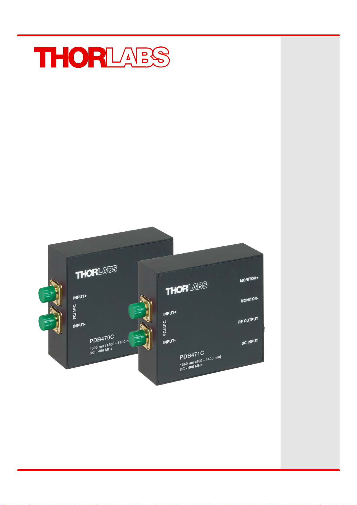
Balanced Amplified Photodetectors
PDB48xC-AC
Operation Manual
2019

Version:
Date:
1.6
14-Jan-2019
Item No.:
M-0009-510-666
Copyright © 2019 Thorlabs

Contents
Foreword
2
1 General Information 3
2 Installation 4
3 Operating Instruction 5
4 Maintenance and Service 10
5 Appendix 11
31.1 Safety
31.2 Ordering Codes and Accessories
42.1 Parts List
42.2 Getting Started
53.1 Operating Principle
63.2 Optical Inputs
63.3 Electrical Outputs
73.4 Mounting
83.5 CMRR and Frequency Response
93.6 Recommendations
125.1 Technical Data
135.1.1 Individual Diagrams PDB480C-AC
155.1.2 Individual Diagrams PDB481C-AC
175.2 Dimensions
185.3 Certifications and Compliances
195.4 Warranty
195.5 Copyright and Exclusion of Reliability
205.6 Thorlabs Worldwide Contacts and WEEE Policy

We aim to develop and produce the best solution for your application
in the field of optical measurement technique. To help us to live up to
your expectations and constantly improve our products we need
your ideas and suggestions. Therefore, please let us know about
possible criticism or ideas. We and our international partners are
looking forward to hearing from you.
Thorlabs GmbH
Warning
Sections marked by this symbol explain dangers that might result in
personal injury or death. Always read the associated information
carefully, before performing the indicated procedure.
Attention
Paragraphs preceded by this symbol explain hazards that could
damage the instrument and the connected equipment or may cause
loss of data.
Note
This manual also contains "NOTES" and "HINTS" written in this form.
Please read this advice carefully!
2
© 2019 Thorlabs

1 General Information
1 General Information
Thorlabs PDB48xC-AC Balanced Amplified Photodetectors consist of two well-matched, fiber
coupled photodiodes with length matched fibers and an ultra-low noise, ultra-low distortion
high-speed transimpedance amplifier that generates an output voltage (RF OUTPUT) proportional to the difference between the photo current in the two photodiodes, i.e. the two optical input signals. Additionally, the unit has two fast monitor outputs (MONITOR+ and MONITOR-) to
measure the individual optical input power level as well as low frequency (up to 3 MHz) modulated signals on each detector separately.
An adapter for post mounting can be attached to the bottom or side surface of the PDB48xC-
AC housing. This adapter supports #8-32 as well as M4 post mounts.
The PDB48xC-AC is supplied with an external linear power supply.
The “Getting Started” section gives an overview of how to set up the PDB48xC-AC Balanced
Amplified Photodetectors. Subsequent sections contain detailed information about principle of
operation, operating suggestions and technical specifications.
4
1.1 Safety
Attention
The safety of any system incorporating the equipment is the responsibility of the assembler of the system.
All statements regarding safety of operation and technical data in this instruction manual
will only apply when the unit is operated correctly as it was designed for.
Do not remove covers! Do not open the cabinet. There are no parts serviceable by the
operator inside!
This precision device is only serviceable if properly packed into the complete original
packaging including the plastic foam sleeves. If necessary, ask for replacement packaging.
Refer servicing to qualified personnel!
Only with written consent from Thorlabs may changes to single components be made or
components not supplied by Thorlabs be used.
1.2 Ordering Codes and Accessories
PDB480C-AC 1.6 GHz, fixed gain, ultra-low distortion Balanced Amplified Photodetector with
fiber length matched pigtailed InGaAs photo diodes, fiber SMF28
PDB481C-AC 1.0 GHz, fixed gain, ultra-low distortion Balanced Amplified Photodetector with
fiber length matched pigtailed InGaAs photo diodes, fiber HI1060
© 2019 Thorlabs
3

PDB48xC-AC
2 Installation
This section is intended to provide information how to set up quickly the PDB48xC-AC Balanced Amplified Photodetectors. More details and advanced features are described in further
sections.
2.1 Parts List
Inspect the shipping container for damage.
If the shipping container seems to be damaged, keep it until you have inspected the contents
and you have inspected the PDB48xC-AC mechanically and electrically.
Verify that you have received the following items within the package:
1. PDB48xC-AC Balanced Amplified Photodetector
2. Adapter Plate with four M2x8 screws and a hex key 1.5, for post-mounting the unit on a
optical table
3. LDS12B power supply (±12 V, 250 mA), switchable to 100 V, 120 V, or 230 V line
voltage
4. Operation manual
2.2 Getting Started
Note
Please check prior to operation, if the indicated line voltage range on the power supply matches
with your local mains voltage! If you want use your own power supply, Thorlabs offers an appropriate power connector cable.
· Carefully unpack the unit and accessories. If any damage is noticed, do not use the unit.
Contact Thorlabs and have us replace the defective unit.
· If required, mount the unit on your optical table or application. Therefore, mount the adapter
plate on bottom or side wall using the four M2x8 screws first. The adapter plate has two
mounting holes, M4 and #8-32. The M4 thread is marked. These threads can be used for
mounting onto Thorlabs posts.
· Set the power supply to your local mains voltage (100, 120, or 230 VAC):
· Connect the DC output cable of the power supply to the POWER IN jack.
· Connect the power supply to the AC outlet, turn power supply on
· Connect RF OUTPUT with coaxial cable to the data acquisition device. Please note, that a
50 W impedance device should be used for best RF performance.
· If necessary, connect monitor outputs (MONITOR+, MONITOR-) to measure the optical in-
put power for each channel individually.
© 2019 Thorlabs4

3 Operating Instruction
3 Operating Instruction
· Turn the power switch of the power supply to I. The green LED next to the DC input connector indicates correct power supply.
· Connect the optical source(s) to the optical input(s). Please note that the PDB48xC-AC is
designed for FC/APC connectors!
· MONITOR outputs can be used for convenient alignment of a coarse input power balance.
The maximum output voltage swing of the MONITOR outputs is 10V for high impedance
loads. Saturation of the MONITOR outputs will occur at optical input power greater than
1 mW.
· The RF output signal must not exceed the maximum RF OUTPUT power at 1 dB compression (see Technical Data ) to avoid saturation.
· For balanced operation illuminate both photodetectors simultaneously and use the
MONITOR outputs to fine-tune the optical power balance by observing voltage on a digital
voltmeter or other low-frequency measurement device.
· After finishing measurements, turn power off.
Attention
12
The damage threshold of the photo diodes is 10 mW (PDB480C-AC) resp. 5 mW (PDB481CAC)! Exceeding this value will permanently destroy the detector!
3.1 Operating Principle
Thorlabs PDB48xC-AC Balanced Amplified Photodetectors consist of two well-matched, pigtailed photodiodes and an ultra-low noise, ultra-low distortion high-speed transimpedance amplifier that generates an output voltage (RF OUTPUT) proportional to the difference between the
photo currents of the two photodiodes, i.e. the difference between the two optical input signals.
Additionally, the unit has two monitor outputs (MONITOR+ and MONITOR-) to observe the optical input power level on each photodiode separately. Due to their increased cut-off frequency,
these outputs can also be used to measure low frequency modulated signals on each detector
separately. This allows a signal normalization up to 3 MHz.
The PDB48xC-AC is powered by an external linear power supply (±12 V, 250 mA - included)
via a PICO M8 power connector.
© 2019 Thorlabs
5

PDB48xC-AC
Below is a functional block diagram of the PDB48xC-AC Balanced Amplified Photodetectors:
3.2 Optical Inputs
The PDB48xC-AC comes with fiber-coupled optical inputs. Both photo detectors are SMF28
(PDB480C-AC) resp. HI1060 (PDB481C-AC) pigtailed and FC/APC connectorized. For this
reason, a free space beam coupling directly to the PDB48xC-AC is not possible
The PDB48xC-AC can be used in balanced mode (both inputs are illuminated) as well as in
single detector mode.
In order to avoid saturation, the output signal level should not exceed the RF output power 1dB-compression point.
Attention
The damage threshold of the photo diodes is 10 mW (PDB480C-AC) resp. 5 mW (PDB481CAC)! Exceeding this value will permanently destroy the photo diode!
Note
Take care for clean fiber connectors prior to attach them to the PDB48xC-AC's optical inputs!
Clean and dust free connections are essential to minimize coupling loss and back reflections.
3.3 Electrical Outputs
The Thorlabs PDB48xC-AC has three SMA output connectors:
· MONITOR +
· MONITOR -
· RF OUTPUT
RF OUTPUT delivers an output voltage proportional to the difference between the photo currents of the two photodiodes This voltage can by calculated to:
with:
Â(l
) - responsivity of the photo diode at given wavelength
© 2019 Thorlabs6

3 Operating Instruction
P
opt,1
and P
- optical input power
opt,2
G - transimpedance gain of the RF output
The responsivity Â(l) for a given wavelength can be read from the individual curves in section
Technical Data to estimate the RF OUTPUT voltage. Please note that the given responsivity
curves represent typical values - individual responsivity may deviate.
The maximum RF OUTPUT power is typically + 18 dBm at 1 dB compression. To explain that:
An ideal amplifier would be a linear device - it's gain is constant at any input power level. In
reality, the output power of the amplifier is limited (e.g. by supply voltage). That means, with increased input power the amplifier becomes saturated. Before the saturation is reached, a reduction in gain takes place - the result is a compression effect. The 1 dB compression point is
defined as the output power where the gain is 1 dB less than the small signal gain.
In order to avoid saturation, the output signal level should not exceed this 1-dB-compression
point.
MONITOR Outputs
The signal monitor outputs (MONITOR+ and MONITOR-) allow observation of the input power
level and can be used as individual power indicators. These outputs can also be used to measure RF (up to 3 MHz) modulated signals on each detector separately. The maximum output
voltage swing of the MONITOR output is +10 V for high impedance loads (+1.5 V into 50 W).
Saturation of MONITOR outputs will occur at optical input power level greater than 1 mW, depending on the detector's wavelength response.
The amplifier offset voltage is factory set to zero at 23°C ambient temperature. A small drift during a short warm-up period (~5min) may occur. For exact DC light level measurements a constant temperature environment is recommended.
3.4 Mounting
The PDB48xC-AC is housed in a rugged shielded aluminum enclosure.
For post mounting an adapter can be attached to the bottom or side surface using four M2x8
screws (see below). This adapter supports #8-32 as well as M4 post mounts. The M4 tread is
marked.
© 2019 Thorlabs
7

PDB48xC-AC
3.5 CMRR and Frequency Response
An important specification for balanced amplifiers is it's ability to suppress common mode
noise, which is reflected in the Common Mode Rejection Ratio (CMRR). In the setup as described below, the Device under Test (DuT) - here a PDB48xC-AC - is tested for CMRR. A
common mode signal is generated, which is canceled out when the amplifier is in balanced
mode.
A network analyzer is used as signal generator (output A) and receiver (input B) The receiver is
synchronized with the signal generator and measures selectively at the same frequency. A
laser light source is modulated by the signal generator (port A) and acts as transmitter. To the
laser output a 3 dB fusion coupler is connected, splitting the modulated light signal into two
paths. Depending on the measurement task, one or both coupler outputs are connected to the
inputs of the DuT. The output of the DuT that should be measured is connected to the network
analyzers Port B.
Frequency response measurements
The frequency response of each signal path can be measured by connecting only one coupler
output to the appropriate input. This way, the frequency response curves of the RF OUTPUT
from INPUT + and INPUT- can be measured, as well as the frequency responses of the
MONITOR outputs, as shown in the individual technical data.
CMRR measurement
For Common Mode Rejection measurement, both outputs of the fusion coupler are connected
to both inputs of the DuT. The optical power level at both inputs must be well matched ("balanced") in order to achieve the optimal common mode suppression. Now the common mode rejection can be measured as a function of frequency. The frequency response of the RF
OUTPUT must be considered when calculating the CMRR - it is the difference between the RF
OUTPUT signal at a given frequency and the measured common mode or balanced output signal - at the same frequency. Typical measurement curves can be found in the individual technical data.
© 2019 Thorlabs8

3 Operating Instruction
3.6 Recommendations
Thorlabs PDB48xC-AC Balanced Amplified Photodetectors can eliminate noise sources to allow precise measurements. The PDB48xC-AC is designed to be used in a dual beam setup:
one optical path for measurement and one invariant reference path. If set up properly, the
PDB48xC-AC can reduce common mode noise for more than 25 dB over the specified frequency range. Below are given some recommendations to achieve an optimal common mode
suppression:
· To obtain the maximum possible common mode rejection (common mode noise suppres-
sion), equal power levels on each photodetector are essential. Any power imbalance will be
amplified and hence decrease the possible noise reduction.
· Equal optical path lengths are very important for common mode noise suppression especially
at higher frequencies. Any path length difference will introduce a phase difference between
the two signals, which will decrease the noise reduction capability of the balanced detector.
The figure below shows the maximum allowed path length difference in fiber to obtain a desired CMRR.
· Avoid etalon effects (interference fringes caused between two optical surfaces) in optical
paths. Using angle polished optical connectors will greatly reduce etalon effects in a fiber
based setup. Effects like residual frequency modulation, polarization noise, polarization
wiggle or spatial modulation can also degrade common mode noise suppression. For further
details contact Thorlabs. In general, reducing sources of differential losses in the optical
paths (other than the measurement itself) will improve the common mode noise reduction.
· Another critical point can be electrostatic coupling of electrical noise associated with ground
loops. In most cases an electrically isolated post (see Thorlabs parts TRE or TRE/M) will
suppress electrical noise coupling. Always try to identify the electrical noise sources and increase the distance to the PDB48xC-AC Balanced Detector. Different common ground points
can also be tested.
© 2019 Thorlabs
9

PDB48xC-AC
4 Maintenance and Service
Protect the PDB48xC-AC from adverse weather conditions. The PDB48xC-AC is not water resistant.
Attention
To avoid damage to the instrument, do not expose it to spray, liquids or solvents!
The unit does not need a regular maintenance by the user. It does not contain any modules
and/or components that could be repaired by the user himself. If a malfunction occurs, please
contact Thorlabs for return instructions.
Do not remove covers!
To clean the PDB48xC-AC series housing, use a mild detergent and damp cloth. Do not soak
the unit in water or use solvent based cleaners.
Cleaning of the fiber connectors
The photodiodes of the PDB48xC-AC
are pigtailed with single mode fiber
and connectorized by FC/APC connectors. Clean and dust-free surfaces
of the ferrule tips are essential to
minimize coupling losses. If the connectors are suspected to be soiled,
the ferrule tips can be cleaned this
way:
Remove the two screws (1), fixing the
front part (2) of the switchable adapter. Detach the front part (2) an
clean the ferrule tip using a lint-free
tissue damped with alcohol or propanol. The ferrule receptacle of the
front part (2) can be cleaned from
dust using compressed air (duster).
When mounting the front adapter, take care for it's correct orientation: The cylindrical key of the
front part must match with it's counterpart in the PDB48xC-AC's housing.
Warning
The screws (3), fixing the base of the switchable adapter to the housing, must not be removed!
© 2019 Thorlabs10

5 Appendix
5 Appendix
Comments and explanations to the individual specifications
- Typical responsivity is the responsivity Â(l) of the photo diode at the stated wavelength.
- Transimpedance [V/A] is the ratio of output voltage to photo current, it is wavelength inde-
pendent.
- Conversion gain [V/W] is the ratio of output voltage to input optical power, by other words
G
CONV
= G
TRANS
× Â(l)
This formula shows, that the conversion gain is dependent on the actual wavelength. In
specifications, it is given only for the indicated operating wavelength.
- NEP (Noise Equivalent Power) is stated for 30 kHz to 100 MHz frequency range.
- Overall output voltage noise [V
] is the value which can be measured across a 50 W
RMS
load at large bandwidth, e.g., if connect the RF output to a 50 W terminated scope input.
- Max. input power is the damage threshold of the photo diode.
- Typical noise spectra (diagrams): These spectra were measured using an electrical spec-
trum analyzer (resolution bandwidth 100 kHz, video bandwidth 10 kHz). The INPUTs of the
balanced detectors under test were blocked. The lower curve in the diagram was measured
with the same setup and the balanced detectors under test switched off, i.e., it represents
the measurement system’s noise floor.
- Monitor outputs are designed for use with high impedance loads (e.g., high-Z scope input
etc.), but can also drive 50 W loads. Monitor outputs conversion gain is given for the indicated operating wavelength and high impedance load.
- Typical frequency response curves are measured using the setup described in section
"CMRR and Frequency Response"
8
© 2019 Thorlabs
11

PDB48xC-AC
Item #
PDB480C-AC
PDB481C-AC
Detector
Detector Type
InGaAs / PIN
Optical Inputs
FC/APC (SMF28e+ inside)
FC/APC (HI1060 inside)
Coupling Loss
< 0.5 dB (typ. < 0.3 dB)
<1.0 dB (typ. < 0.4 dB)
Operating Wavelength
1300 nm
(1200 - 1700 nm)
1060 nm
(900 - 1400 nm)
Responsivity, typ.
0.85 A/W @ 1300 nm
0.72 A/W @ 1060 nm
Active Detector Diameter
0.075 mm
0.080 mm
Optical Back Reflection
< -40 dB
Photo Diode Damage Threshold
10 mW
5 mW
RF OUTPUT
RF OUTPUT Bandwidth (3dB)
30 kHz to 1.6 GHz
30 kHz to 1.0 GHz
Common Mode Rejection Ratio
>25 dB (typ. >30 dB)
RF OUTPUT Transimpedance Gain
50 W load
16 x 103 V/A
RF OUTPUT Conversion Gain
50 W load
14.4 x 10³ V/W @ 1300 nm
11.5 x 10³ V/W @ 1060 nm
RF OUTPUT Power at 1 dB compression
50 W load
min. +16.5 dBm
typ. +18 dBm
RF OUTPUT Coupling
AC coupling only
RF Output Impedance
50 W
Minimum NEP (30 kHz to 100 MHz)
Overall Output Voltage Noise
< 9 mV
RMS
< 6.5 mV
RMS
MONITOR Outputs
MONITOR Output Impedance
200 W
MONITOR Output Bandwidth (3 dB)
DC to 3 MHz
MONITOR Output Conversion Gain
High Z load
9 V/mW @ 1300 nm
7.2 V/mW @ 1060 nm
MONITOR Output Voltage Swing
High Z load
max. 10 V
Overall Output Voltage Noise
< 0.65 mV
RMS
DC Offset
< ± 2 mV
General
Electrical Outputs
SMA
DC Power Supply
± 12V @ 250mA
Operating Temperature Range 1)
0 - 40 °C
Storage Temperature Range
-40 to 70 °C
Dimensions (W x H x D)
85 mm x 80 mm x 30 mm
Weight
0.35
5.1 Technical Data
1
) non-condensing
Values for transimpedance and conversion gain are lossless gain values, i.e., losses introduced by FC/APC connectors (typically 0.15 to 0.35 dB) are not considered.
All technical data are valid at 23 ± 5°C and 45 ± 15% rel. humidity (non condensing)
© 2019 Thorlabs12

5.1.1 Individual Diagrams PDB480C-AC
PDB480C-AC - Typical Detector Responsivity
PDB480C-AC - Typical RF OUTPUT Frequency Response
5 Appendix
© 2019 Thorlabs
13

PDB48xC-AC
PDB480C-AC - Typical MONITOR Output Frequency Response
PDB480C-AC - Typical RF-OUTPUT Spectral Noise
© 2019 Thorlabs14

5.1.2 Individual Diagrams PDB481C-AC
PDB481C-AC - Typical Detector Responsivity
PDB481C-AC - Typical RF OUTPUT Frequency Response
5 Appendix
© 2019 Thorlabs
15

PDB48xC-AC
PDB481C-AC - Typical MONITOR OUTPUT Frequency Response
PDB481C-AC - Typical RF-OUTPUT Spectral Noise
© 2019 Thorlabs16

5.2 Dimensions
PDB48xC-AC Mechanical Drawing
5 Appendix
© 2019 Thorlabs
17

PDB48xC-AC
5.3 Certifications and Compliances
© 2019 Thorlabs18

5 Appendix
5.4 Warranty
Thorlabs warrants material and production of the PDB48xC-AC for a period of 24 months starting with the date of shipment. During this warranty period Thorlabs will see to defaults by repair
or by exchange if these are entitled to warranty.
For warranty repairs or service the unit must be sent back to Thorlabs. The customer will carry
the shipping costs to Thorlabs, in case of warranty repairs Thorlabs will carry the shipping costs
back to the customer.
If no warranty repair is applicable the customer also has to carry the costs for back shipment.
In case of shipment from outside EU duties, taxes etc. which should arise have to be carried by
the customer.
Thorlabs warrants the hard- and/or software determined by Thorlabs for this unit to operate
fault-free provided that they are handled according to our requirements. However, Thorlabs
does not warrant a fault free and uninterrupted operation of the unit, of the software or firmware
for special applications nor this instruction manual to be error free. Thorlabs is not liable for
consequential damages.
Restriction of Warranty
The warranty mentioned before does not cover errors and defects being the result of improper
treatment, software or interface not supplied by us, modification, misuse or operation outside
the defined ambient stated by us or unauthorized maintenance.
Further claims will not be consented to and will not be acknowledged. Thorlabs does explicitly
not warrant the usability or the economical use for certain cases of application.
Thorlabs reserves the right to change this instruction manual or the technical data of the described unit at any time.
5.5 Copyright and Exclusion of Reliability
Thorlabs has taken every possible care in preparing this document. We however assume no liability for the content, completeness or quality of the information contained therein. The content
of this document is regularly updated and adapted to reflect the current status of the hardware
and/or software. We furthermore do not guarantee that this product will function without errors,
even if the stated specifications are adhered to.
Under no circumstances can we guarantee that a particular objective can be achieved with the
purchase of this product.
Insofar as permitted under statutory regulations, we assume no liability for direct damage, indirect damage or damages suffered by third parties resulting from the purchase of this product. In
no event shall any liability exceed the purchase price of the product.
Please note that the content of this document is neither part of any previous or existing agreement, promise, representation or legal relationship, nor an alteration or amendment thereof. All
obligations of Thorlabs result from the respective contract of sale, which also includes the complete and exclusively applicable warranty regulations. These contractual warranty regulations
are neither extended nor limited by the information contained in this document. Should you require further information on this product, or encounter specific problems that are not discussed
in sufficient detail in the document, please contact your local Thorlabs dealer or system installer.
All rights reserved. This document may not be reproduced, transmitted or translated to another
language, either as a whole or in parts, without the prior written permission of Thorlabs.
Copyright © Thorlabs 2019. All rights reserved.
© 2019 Thorlabs
19

PDB48xC-AC
US
A, Canada, and South America
Thorlabs, Inc.
56 Sparta Avenue
Newton, NJ 07860
USA
Tel: 973-300-3000
Fax: 973-300-3600
www.thorlabs.com
www.thorlabs.us (West Coast)
Email: sales@thorlabs.com
Support: techsupport@thorlabs.com
UK and Ireland
Thorlabs Ltd.
1 Saint Thomas Place, Ely
Cambridgeshire CB7 4EX
United Kingdom
Tel: +44-1353-654440
Fax: +44-1353-654444
www.thorlabs.com
Email: sales.uk@thorlabs.com
Support: techsupport.uk@thorlabs.com
Europe
Thorlabs GmbH
Hans-Böckler-Str. 6
85221 Dachau
Germany
Tel: +49-8131-5956-0
Fax: +49-8131-5956-99
www.thorlabs.de
Email: europe@thorlabs.com
Scandinavia
Thorlabs Sweden AB
Bergfotsgatan 7
431 35 Mölndal
Sweden
Tel: +46-31-733-30-00
Fax: +46-31-703-40-45
www.thorlabs.com
Email: scandinavia@thorlabs.com
France
Thorlabs SAS
109, rue des Côtes
78600 Maisons-Laffitte
France
Tel: +33-970 444 844
Fax: +33-825 744 800
www.thorlabs.com
Email: sales.fr@thorlabs.com
Brazil
Thorlabs Vendas de Fotônicos Ltda.
Rua Riachuelo, 171
São Carlos, SP 13560-110
Brazil
Tel: +55-16-3413 7062
Fax: +55-16-3413 7064
www.thorlabs.com
Email: brasil@thorlabs.com
Japan
Thorlabs Japan, Inc.
3-6-3 Kitamachi
Nerima-ku, Tokyo 179-0081
Japan
Tel: +81-3-6915-7701
Fax: +81-3-6915-7716
www.thorlabs.co.jp
Email: sales@thorlabs.jp
China
Thorlabs China
Room A101, No. 100
Lane 2891, South Qilianshan Road
Putuo District
Shanghai 200331
China
Tel: +86-21-60561122
Fax: +86-21-32513480
www.thorlabs.com
Email: chinasales@thorlabs.com
5.6 Thorlabs Worldwide Contacts and WEEE Policy
Thorlabs verifies our compliance with the WEEE (Waste Electrical and Electronic Equipment) directive of the European Community and the corresponding national laws. Accordingly, all end users in the EC may return “end of life” Annex I category electrical and
electronic equipment sold after August 13, 2005 to Thorlabs, without incurring disposal
charges. Eligible units are marked with the crossed out “wheelie bin” logo (see right),
were sold to and are currently owned by a company or institute within the EC, and are
not dissembled or contaminated. Contact Thorlabs for more information. Waste treatment is your own responsibility. “End of life” units must be returned to Thorlabs or
handed to a company specializing in waste recovery. Do not dispose of the unit in a litter
bin or at a public waste disposal site.
© 2019 Thorlabs20

www.thorlabs.com
 Loading...