


PDA05CF2
InGaAs Amplified
Fixed Gain Detector
User Guide

InGaAs Amplified Fixed Gain Detector
Table of Contents
Chapter 1 Warning Symbol Definitions ........................................... 1
Chapter 2 Description ........................................................................ 2
Chapter 3 Setup .................................................................................. 3
Chapter 4 Operation........................................................................... 4
4.1. Theory of Operation ...................................................... 4
4.2. Responsivity ................................................................. 4
4.3. Dark Current ................................................................. 4
4.4. Bandwidth and Response .............................................. 5
4.5. Terminating Resistance ................................................. 5
Chapter 5 Troubleshooting ............................................................... 6
Chapter 6 Specifications ................................................................... 7
6.1. Response Curve ............................................................. 9
6.2. Mechanical Drawing ................................................... 10
Chapter 7 Certificate of Conformance ........................................... 11
Chapter 8 Regulatory ....................................................................... 12
Chapter 9 Thorlabs Worldwide Contacts....................................... 13

InGaAs Amplified Fixed Gain Detector Chapter 1: Warning Symbol Definitions
Rev B, January 3, 2018 Page 1
Chapter 1 Warning Symbol Definitions
Below is a list of warning symbols you may encounter in this manual or on your
device.
Symbol
Description
Direct Current
Alternating Current
Both Direct and Alternating Current
Earth Ground Terminal
Protective Conductor Terminal
Frame or chassis Terminal
Equipotentiality
On (Supply)
Off (Supply)
In Position of a Bi-Stable Push Control
Out Position of a Bi-Stable Push Control
Caution, Risk of Electric Shock
Caution, Hot Surface
Caution, Risk of Danger
Warning, Laser Radiation
Caution: ESD Sensitive Components

InGaAs Amplified Fixed Gain Detector Chapter 2: Description
Page 2 TTN134810-D02
Chapter 2 Description
The PDA05CF2 is an amplified, Indium Gallium Arsenide (InGaAs) detector
designed for detection of light signals ranging from 800 to 1700 nm. A buffered
output drives 50 Ω load impedances up to 5 V. The PDA05CF2 housing includes
a removable threaded coupler (SM1T1) and retainer ring (SM1RR) that is
compatible with any number of Thorlabs 1” threaded accessories. This allows
convenient mounting of external optics, light filters, apertures, as well as
providing an easy mounting mechanism using Thorlabs’ cage assembly
accessories.
ESD Caution
The components inside this instrument are ESD sensitive. Take all
appropriate precautions to discharge personnel and equipment before
making any electrical connections to the unit.

InGaAs Amplified Fixed Gain Detector Chapter 3: Setup
Rev B, January 3, 2018 Page 3
Chapter 3 Setup
The detector can be set up in many different ways using our extensive line of
adapters. However, the detector should always be mounted and secured for best
operation.
1. Unpack the optical head, install either an imperial or metric optical post
into one of the mounting holes located on the bottom and side of the
sensor, and mount using a post holder. Note that these detectors
feature tapped holes that accept both 8-32 and M4 threads, so using
either imperial or metric TR posts is possible.
2. Connect the power supply 3-pin plug into the power receptacle on the
PDA05CF2.
3. Plug the power supply into a 50 to 60Hz, 100 V / 120 V / 230 V power
outlet.
4. Attach a 50 Ω coax cable (i.e. RG-58U) to the output of the PDA. When
running cable lengths longer than 12" we recommend terminating the
opposite end of the coax with a 50 Ω resistor (Thorlabs p/n T4119) for
maximum performance. Connect the remaining end to a measurement
device such as an oscilloscope or high speed DAQ card. Caution: Many
high speed oscilloscopes have input impedances of 50 Ω. In this case,
do not install a 50 Ω terminator. The combined loads will equal 25 Ω
which could allow ~135 mA of output current. This will damage the
output driver of the PDA05CF2.
5. Power the PDA05CF2 on using the power switch located on the top side
of the unit.
Caution!
The PDA05CF2 was designed to allow maximum accessibility to the
photodetector by having the active area surface of the diode flush with the
outside of the PDA housing. When using fiber adapters, make sure that the
fiber ferrule does not crash into the detector. Failure to do so may cause
damage to the diode and/or the fiber.
6. Install any desired filters, optics, adapters, or fiber adapters to the input
aperture.
7. During alignment, take appropriate precautions, such as using reduced
radiation power, or other precautions, and use proper eye and/or skin
protection as recommended by the radiation source manufacturer.
8. Apply a light source to the detector.

InGaAs Amplified Fixed Gain Detector Chapter 4: Operation
Page 4 TTN134810-D02
Chapter 4 Operation
4.1. Theory of Operation
Thorlabs PDA series are ideal for measuring both pulsed and CW light sources.
The PDA05CF2 includes a reverse-biased PIN photo diode, mated to a fixed
gain transimpedance amplifier, and packaged in a rugged housing.
4.2. Responsivity
The responsivity of a photodiode can be defined as a ratio of generated
photocurrent (IPD) to the incident light power (P) at a given wavelength:
4.3. Dark Current
Dark current is leakage current which flows when a bias voltage is applied to a
photodiode. The PDA with Transimpedance Amplifier does control the dark
current flowing out. Looking at the figure above, it can be noted that Point B is
held at ground and the amplifier will try to hold point A to “Virtual Ground”. This
minimizes the effects of dark current present in the system.
The dark current present is also affected by the photodiode material and the size
of the active area. Silicon devices generally produce low dark current compared
to germanium devices which have high dark currents. The table below lists
several photodiode materials and their relative dark currents, speeds, sensitivity,
and costs. Please note that sensitivity values in the table are typical values;
Thorlabs offers photodetectors with sensitivity ranges that vary from those shown
below.

InGaAs Amplified Fixed Gain Detector Chapter 4: Operation
Rev B, January 3, 2018 Page 5
Material
Dark
Current
Speed
Sensitivity1
(nm)
Cost
Silicon (Si)
Low
High
400 – 1000
Low
Germanium (Ge)
High
Low
900 – 1600
Low
Gallium Phosphide (GaP)
Low
High
150 – 550
Med
Indium Gallium Arsenide
(InGaAs)
Low
High
800 – 1800
Med
Extended Range: Indium
Gallium Arsenide (InGaAs)
High
High
1200 – 2600
High
4.4. Bandwidth and Response
For the PDA detectors, the gain of the detector is dependent on the feedback
element (Rf). The bandwidth of the detector can be calculated using the
following:
Where GBP is the amplifier gain bandwidth product and CD is the sum of the
photodiode junction capacitance and the amplifier capacitance.
4.5. Terminating Resistance
The maximum output of the PDA05CF2 is 10 V for high impedance loads (i.e.
R
Load
> 5 kΩ) and 5 V for 50 Ω loads. Adjust the gain so that the measured signal
level out of the PDA05CF2 is below 10 V (5 V with a 50 Ω load) to avoid
saturation.
For low terminating resistors, <5 kΩ or 1% error, an additional factor needs to be
considered. The output of the PDA includes a 50 Ω series resistor (Rs). The
output load creates a voltage divider with the 50 Ω series resistor as follows:
Note that we already include the scale factor in our specification for the gain at
50 Ω. Refer to the table in Chapter 6 for additional performance specifications.
1
Approximate values; actual wavelength values will vary.

InGaAs Amplified Fixed Gain Detector Chapter 5: Troubleshooting
Page 6 TTN134810-D02
Chapter 5 Troubleshooting
Problem
Suggested Solutions
There is no signal response.
Verify that the power is switched on and all
connections are secure.
Verify the proper terminating resistor is installed if
using a Voltage measurement device.
Verify that the optical signal wavelength is within
the specified wavelength range.
Verify that the optical signal is illuminating the
detector active area.
Output Voltage will not increase.
Detector Output is skewed.
Check to make sure the detector is not saturated.
Refer to the Output Voltage spec. in the
Specifications table.
Install a 1" Lens Tube (SM1L10) to the thread
coulpler (SM1T1) to baffle any external light
sources to see if this improves the response.

InGaAs Amplified Fixed Gain Detector Chapter 6: Specifications
Rev B, January 3, 2018 Page 7
Chapter 6 Specifications
All performance specifications are typical, performed at 25 °C ambient
temperature, and assume a 50 Ω load, unless stated otherwise.
Electrical Specifications2
Detector
-
InGaAs
Active Area
-
Ø0.5 mm (0.2 mm2)
Wavelength Range
λ
800 to 1700 nm
Peak Wavelength
λ
p
1590 nm (Typ.)
Peak Response
( λ
p
)
1.04 A/W (Typ.)
Small Signal Bandwidth
-
150 MHz
NEP (λ p)
W/√Hz
1.26 x 10
-11
Noise (RMS)
-
2 mV
rms
Max Ouput Current
I
OUT
100 mA
Dark Offset
-
±20 mV
Load Impedance
-
50 Ω to Hi-Z
Transimpedance Gain
-
5 x 10³ V/A (50 Ω)
1 x 10⁴ V/A (Hi-Z)
Output Voltage
V
OUT
0 to 5 V (50 Ω)
0 to 10 V (Hi-Z)
2
The PDA05CF2 has a 50 Ω series terminator resistor (i.e. in series with amplifier output). This
forms a voltage divider with any load impedance (e.g. 50 Ω load divides signal in half).
InGaAs Amplified Fixed Gain Detector Chapter 6: Specifications
Page 8 TTN134810-D02
3
Measured from the active area to the start of the threads on the housing body. The detector
active area surface is flush with the front of the housing body.
4
Although the power supply is rated for 6 W, the detector’s actual usage is <5 W over the full
operating range.
General
On/Off Switch
Slide
Output
BNC (DC Coupled)
Package Size
2.79" x 1.96" x 0.89"
(70.9 mm x 49.8 mm x 22.5 mm)
PD Surface Depth3
0.09" (2.2 mm)
Weight, Detector Only
0.10 kg
Accessories
SM1T1 Coupler
SM1RR Retainer Ring
Operating Temp
10 to 50 °C
Storage Temp
-25 to 70 °C
AC Power Supply
AC – DC Converter
Input Power4
6 W
100 V / 120 V / 230 V, 50 – 60 Hz

InGaAs Amplified Fixed Gain Detector Chapter 6: Specifications
Rev B, January 3, 2018 Page 9
6.1. Response Curve
900 1000 1100 1200 1300 1400 1500 1600800 1700
0.0
0.2
0.4
0.6
0.8
1.0
1.2
1.4
PDA05CF2 Responsivity
Responsivity (A/W)
Wavelength (nm)
InGaAs Amplified Fixed Gain Detector Chapter 6: Specifications
Page 10 TTN134810-D02
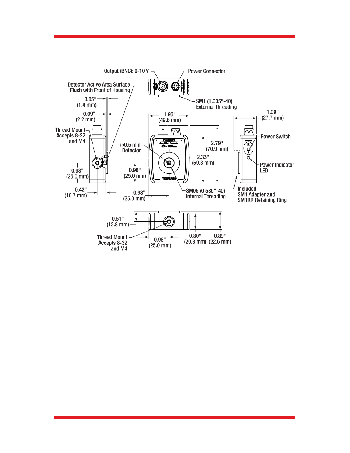
6.2. Mechanical Drawing

InGaAs Amplified Fixed Gain Detector Chapter 7: Certificate of Conformance
Rev B, January 3, 2018 Page 11
Chapter 7 Certificate of Conformance

InGaAs Amplified Fixed Gain Detector Chapter 8: Regulatory
Page 12 TTN134810-D02
Chapter 8 Regulatory
As required by the WEEE (Waste Electrical and Electronic Equipment Directive)
of the European Community and the corresponding national laws, Thorlabs offers
all end users in the EC the possibility to return “end of life” units without incurring
disposal charges.
This offer is valid for Thorlabs electrical and electronic equipment:
Sold after August 13, 2005
Marked correspondingly with the crossed out
“wheelie bin” logo (see right)
Sold to a company or institute within the EC
Currently owned by a company or institute within
the EC
Still complete, not disassembled and not
contaminated
As the WEEE directive applies to self contained operational electrical and
electronic products, this end of life take back service does not refer to other
Thorlabs products, such as:
Pure OEM products, that means assemblies to be built into a unit by the
user (e.g. OEM laser driver cards)
Components
Mechanics and optics
Left over parts of units disassembled by the user (PCB’s, housings etc.).
If you wish to return a Thorlabs unit for waste recovery, please contact Thorlabs
or your nearest dealer for further information.
Waste Treatment is Your Own Responsibility
If you do not return an “end of life” unit to Thorlabs, you must hand it to a
company specialized in waste recovery. Do not dispose of the unit in a litter bin
or at a public waste disposal site.
Ecological Background
It is well known that WEEE pollutes the environment by releasing toxic products
during decomposition. The aim of the European RoHS directive is to reduce the
content of toxic substances in electronic products in the future.
The intent of the WEEE directive is to enforce the recycling of WEEE. A
controlled recycling of end of life products will thereby avoid negative impacts on
the environment.
Wheelie Bin Logo

InGaAs Amplified Fixed Gain Detector Chapter 9: Thorlabs Worldwide Contacts
Rev B, January 3, 2018 Page 13
Chapter 9 Thorlabs Worldwide Contacts
USA, Canada, and South America
Thorlabs, Inc.
56 Sparta Avenue
Newton, NJ 07860
USA
Tel: 973-300-3000
Fax: 973-300-3600
www.thorlabs.com
www.thorlabs.us (West Coast)
Email: sales@thorlabs.com
Support: techsupport@thorlabs.com
UK and Ireland
Thorlabs Ltd.
1 Saint Thomas Place
Ely CB7 4EX
Great Britain
Tel: +44 (0) 1353-654440
Fax: +44 (0) 1353-654444
www.thorlabs.com
Email: sales.uk@thorlabs.com
Support: techsupport.uk@thorlabs.com
Europe
Thorlabs GmbH
Hans-Böckler-Str. 6
85221 Dachau / Munich
Germany
Tel: +49-(0) 8131-5956-0
Fax: +49-(0) 8131-5956-99
www.thorlabs.de
Email: europe@thorlabs.com
Scandinavia
Thorlabs Sweden AB
Bergfotsgatan 7
431 35 Mölndal
Sweden
Tel: +46-31-733-30-00
Fax: +46-31-703-40-45
www.thorlabs.com
Email: scandinavia@thorlabs.com
France
Thorlabs SAS
109, rue des Côtes
78600 Maisons-Laffitte
France
Tel: +33 (0) 970 444 844
Fax: +33 (0) 825 744 800
www.thorlabs.com
Email: sales.fr@thorlabs.com
Brazil
Thorlabs Vendas de Fotônicos Ltda.
Rua Riachuelo, 171
São Carlos, SP 13560-110
Brazil
Tel: +55-16-3413 7062
Fax: +55-16-3413 7064
www.thorlabs.com
Email: brasil@thorlabs.com
Japan
Thorlabs Japan, Inc.
3-6-3, Kitamachi,
Nerima-ku, Tokyo 179-0081
Japan
Tel: +81-3-6915-7701
Fax: +81-3-6915-7716
www.thorlabs.co.jp
Email: sales@thorlabs.jp
China
Thorlabs China
Room A101, No. 100, Lane 2891,
South Qilianshan Road
Putuo District
Shanghai 200331
China
Tel: +86 (0) 21-60561122
Fax: +86 (0) 21-32513480
www.thorlabschina.cn
Email: chinasales@thorlabs.com

www.thorlabs.com
 Loading...