

OCTG Series,
OCT-LKx, and OCT-RAx
OCT Standard Scanner,
Scan Lens Kit,
and Standard Scanner
Reference Arm Adapter
User Manual

Original User Manual – not translated

Table of Contents
Chapter 1 Warning Symbol Definitions ....................................................................................... 1
Chapter 2 Introduction .................................................................................................................. 2
2.1. Safety ........................................................................................................................ 2
2.2. Care and Maintenance ............................................................................................. 3
2.2.1. Optical Cleaning .............................................................................................................. 3
2.2.2. Service ............................................................................................................................ 3
2.2.3. Accessories and Customization ...................................................................................... 3
Chapter 3 Scanner Compatibility ................................................................................................. 4
Chapter 4 Installation .................................................................................................................... 5
4.1. OCTG Mounting ....................................................................................................... 5
4.2. OCTG Connections .................................................................................................. 6
4.2.1. Connecting the Electrical Control Interface ..................................................................... 6
4.2.2. Connecting the Optical Fiber........................................................................................... 7
4.3. Integration ................................................................................................ ................ 8
Chapter 5 Description ................................................................................................................... 9
5.1. Theory ...................................................................................................................... 9
5.1.1. Signal Generation ........................................................................................................... 9
5.1.2. Limitations ....................................................................................................................... 9
5.2. Optical Design ....................................................................................................... 10
5.2.1. Common Path Setup ..................................................................................................... 10
5.2.2. Dual Path Setup (OCTG-NR) ........................................................................................ 10
5.2.3. Realization..................................................................................................................... 11
5.3. Components ........................................................................................................... 12
5.3.1. OCTG Base Module ...................................................................................................... 13
5.3.2. OCTG Reference Module ............................................................................................. 15
5.3.3. OCT Scan Lens Kit (Accessory) ................................................................................... 16
5.3.4. Reference Arm Adapter (Accessory) ............................................................................ 17
5.3.5. Dove Tail Mount ............................................................................................................ 18
5.4. Dimensions ............................................................................................................ 19
Chapter 6 Troubleshooting ......................................................................................................... 20
Chapter 7 Certifications and Compliance ................................................................................. 21
Chapter 8 Specifications ............................................................................................................. 22
8.1. Reflectivity Scanning Mirror ................................................................................. 23
Chapter 9 Warranty ...................................................................................................................... 24
9.1. Imaging Systems ................................................................................................... 24
9.2. Non-Warranty Repairs ........................................................................................... 24
9.3. Warranty Exclusions ............................................................................................. 24
Chapter 10 Regulatory .................................................................................................................. 25
10.1. Waste Treatment is Your Own Responsibility ..................................................... 25
10.2. Ecological Background ......................................................................................... 25
Chapter 11 Thorlabs OCT Support Contact ................................................................................ 26

Chapter 12 Thorlabs Worldwide Contacts .................................................................................. 27

OCTG Series Scanner Chapter 1: Warning Symbol Definitions
Rev C, April 06, 2016 Page 1
Chapter 1 Warning Symbol Definitions
Below is a list of warning symbols you may encounter in this manual or on your device.
Symbol
Description
Direct Current
Alternating Current
Both Direct and Alternating Current
Earth Ground Terminal
Protective Conductor Terminal
Frame or Chassis Terminal
Equipotentiality
On (Supply)
Off (Supply)
In Position of a Bi-Stable Push Control
Out Position of a Bi-Stable Push Control
Caution: Risk of Electric Shock
Caution: Hot Surface
Caution: Risk of Danger
Warning: Laser Radiation
Caution: Spinning Blades May Cause Harm

OCTG Series Scanner Chapter 2: Introduction
Page 2 MTN004419-D02
Chapter 2 Introduction
2.1. Safety
Please read this manual carefully before operating the OCTG standard scanner. Please also read any
manuals for the systems being connected to the OCTG.
All statements regarding safety and technical specifications will only apply when the unit is operated correctly.
ATTENTION
This equipment is intended for laboratory use only and is not certified for medical
applications, including, but not limited to, life support situations.
WARRANTY WARNING
There are sensitive electronic and optical parts in the OCTG.
Any modification or servicing of this system by unqualified personnel renders Thorlabs free of
any liability.
Any modification or the galvanometer scanners or the camera may cause loss of the factory
optical alignment.
This device can only be returned for service when it is packed into the complete original
packaging, including all foam packing inserts. Please contact Thorlabs’ OCT support
(see Chapter 11) for replacement packaging if the original packaging has been lost.
LASER RADIATION WARNING
When a light source (e.g. SLD, laser) is being coupled into the OCTG, please observe the
appropriate laser safety precautions for your own protection. The appropriate laser safety
precautions depend on the light source coupled into the OCTG.
During normal operations, laser light will be present within the scanner and will also be
emitted from the scanner. Also laser light may be emitted from unexpected locations, such as
if the fiber has been disconnected from the body or if the reference arm has been
disconnected.
In addition, the OCTG is an optical system that can influence the divergence of the beam. This
can cause a change of laser class of the light source, especially if the OCTG is used without
an objective.
Always turn off the light source before changing or adjusting the OCTG configuration or
accessories as the objective, lens kit, reference arm adapter, or sample z-spacer. For Thorlabs
OCT base units, turn off the OCT base unit main power to turn off the light source.

OCTG Series Scanner Chapter 2: Introduction
Rev C, April 06, 2016 Page 3
2.2. Care and Maintenance
The system should be treated with care, particularly during transportation and unpacking. Hitting or dropping
the system can damage the unit and lower system performance. If mishandling occurs, misalignment of the
optical components may occur, leading to a decrease in image quality. In this situation, the system should be
realigned by qualified personnel. Do not store or operate in a damp, closed environment.
Do not store or operate on surfaces that are susceptible to vibrations.0
Do not expose to direct sunlight.
Do not use solvents on or near the equipment.
Keep the unit away from dust, dirt, and airborne contaminants, such as cigarette smoke. The system
is not designed for outdoor use. Protect the equipment from rain, snow, and humidity.
Do not subject the equipment to mechanical and thermal extremes. Protect the equipment from rapid
variations in temperature.
Handle all electrical and fiber connectors with care. Use of excessive force to form electrical or fiber
connections may damage the connectors.
2.2.1. Optical Cleaning
The most common cause of low signal intensity is dirtying of the fiber due to airborne contaminants. To
minimize the fiber’s exposure to air, avoid unnecessary disconnections of the optical fiber patch cable. Ensure
that the connection is tight, and keep the fiber as straight as possible without placing it under tension. It is
also advisable to check the fiber when making other adjustments to the optical system, such as changing the
objective.
Thorlabs’ Fiber Inspection Scope (Item # FS200) can help determine when the fiber needs cleaning. We
recommend our Fiber Connector Cleaner (Item # FCC-7020) for quickly cleaning the fiber tips.
2.2.2. Service
Only trained and approved Thorlabs personnel are allowed to service the system. Please contact Thorlabs’
OCT support (see Chapter 11) for more information.
2.2.3. Accessories and Customization
The OCTG series standard scanners are Thorlabs-qualified accessories for Thorlabs’ OCT Systems (i.e., our
CALLISTO, GANYMEDE, VEGA and TELESTO). We strongly suggest using Thorlabs’ OCT-LKx scan lens
kits as well as OCT-RA reference arm adapter kits with the OCTG as they were specifically designed to work
together.
In order to achieve the intended performance, this scanner should only be used with qualified parts. Please
hold a conversation with Thorlabs’ OCT support (see Chapter 11) to determine if other parts you wish to use
are compatible. Any modification or servicing of this system by unqualified personnel renders the warranty
null and void, leaving Thorlabs free of any liability.

OCTG Series Scanner Chapter 3: Scanner Compatibility
Page 4 MTN004419-D02
Chapter 3 Scanner Compatibility
The OCTG standard scanner is a standalone, preassembled, integrated scanner intended for the use together
with a Thorlabs OCT base unit such as the CALLISTO, VEGA, GANYMEDE or TELESTO series.
This scanner is available in two different setups
The OCTG-xxxNR standard scanner is designed for dual path setups using a dedicated external
reference to create the interferometric signal.
These scanners does NOT comprise an interferometer.
The other OCTG-xxx scanner is designed for common path setups and comprise an interferometer
consisting of a beam splitter and a reference arm creating the interferometric signal. The OCTG-xxx
is available in two versions for different wavelength ranges.
o The OCTG-900 for OCT systems working in the 900 nm regime.
o The OCTG-1300 for OCT systems working in the 1300 nm regime.
In this manual we will use abbreviation for the OCTG scanner as follows:
OCTG OCTG-900; or OCTG-1300
For common statements the abbreviation “OCTG” is used for both setups.
The OCTG scanners are fully compatible with all Thorlabs OCT base units of the CALLISTO, VEGA,
GANYMEDE, and TELESTO series.
The table below gives a short overview of the different standard scanners, their usable wavelength range and
lists preferred OCT base units.
Standard Scanner
Wavelength Range
OCT Base Unit
OCTG-900
850 nm – 1000 nm
CALxxx
GANxxx
OCTG-1300
1200 nm – 1400 nm
TELxxx
OCTG-1300NR
1200 nm – 1400 nm
VEGxxx
Table 1 Usable Wavelength Range of OCT Scanner
The most selective optical component is a mirror mounted on the Y galvanometric scanner of the scanner
set.
A reflectivity graph of the scanning mirror is given in Figure 21.
Detailed information about the spectral performance of the different mirrors are available upon request.
Please contact Thorlabs’ OCT support (see Chapter 11) for details
OCTG Series Scanner Chapter 4: Installation
Rev C, April 06, 2016 Page 5
Chapter 4 Installation
The OCTG standard scanner is a standalone, preassembled, integrated accessory to an OCT base unit. It
should be securely mounted to an optical table or breadboard with minimal vibrations. We recommend
mounting the OCTG to a Thorlabs OCT-Stand.
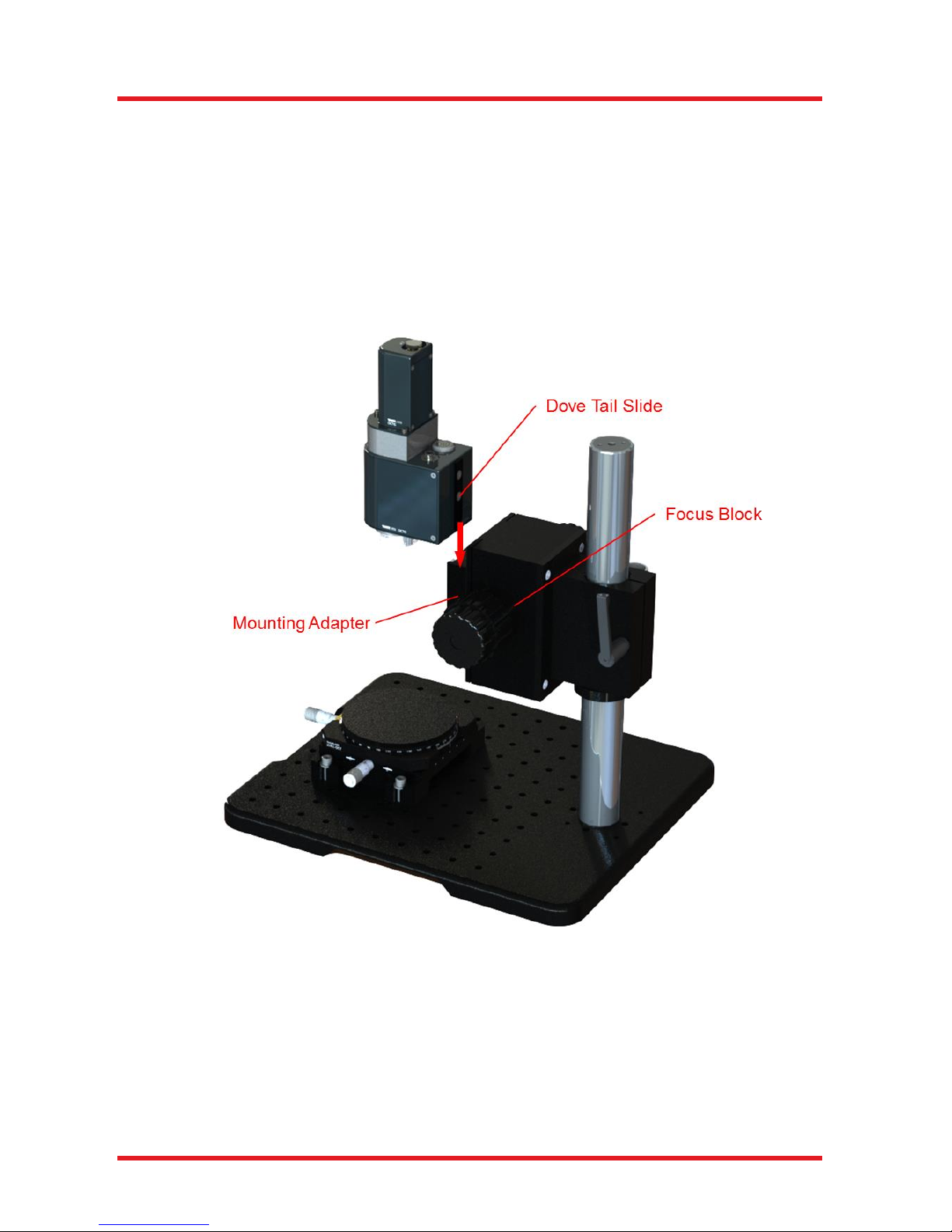
4.1. OCTG Mounting
To mount the OCTG in the OCT-Stand, gently slide the dovetail of the OCTG into the slide of the OCT-Stand.
Figure 1 Mounting the OCTG in the OCT-Stand

OCTG Series Scanner Chapter 4: Installation
Page 6 MTN004419-D02
4.2. OCTG Connections
4.2.1. Connecting the Electrical Control Interface
Attach the included electrical control cable to the OCTG. You may use either side of the cable since the plugs
are identical. The OCT scanner’s electrical control interface is located at the top of the OCTG base module.
Align the red dot of the plug to the alignment mark of the port.
Push the connector into the receptacle until a “click” sound is heard. This click indicates that the connector is
locked.
Figure 2 Installation of the Control Cable Connector at the OCTG
The remaining plug of the electrical control cable will be attached to the OCT base unit. Make sure that the
base unit is switched off.
The connection is located at the rear of the base unit. For installation, align the red dot, facing the alignment
mark in the base unit. Push the connector into the receptacle marked “Control” until a “click” sound is heard.
This click indicates that the connector is locked.

OCTG Series Scanner Chapter 4: Installation
Rev C, April 06, 2016 Page 7
4.2.2. Connecting the Optical Fiber
ATTENTION
When installing the fiber, make sure that the fiber tip does not get contaminated by dust.
Thorlabs’ Fiber Inspection Scope (Item # FS200) and Fiber Connector Cleaner (Item # FBC1)
are useful for keeping the optical path clean.
Do not touch the fiber tip!
Attach the optical fiber to the OCTG, as illustrated in Figure 3 below. Either end of the fiber patch cable may
be used to connect to the OCTG. Remove the dust cap from each fiber end and store them with the system
packaging. The FC/APC fiber connection is located at the top of the OCTG base module side by side with the
electric interface. Insert the fiber tip into the center bore of the fiber connection, than secure the tip by gently
rotating the locking cap clockwise.
The fiber connector needs to be oriented such that alignment key slides into the key slot of the fiber
connector (as shown in Figure 3 below). If the key is NOT properly aligned with respect to the key slot, you
will still be able to screw in the fiber connector, but significant light intensity loss and focal shift will result from
this incorrect connection.
Figure 3 Installation of the Fiber at the OCTG Standard Scanner

OCTG Series Scanner Chapter 4: Installation
Page 8 MTN004419-D02
4.3. Integration
For the full integration into such a system, please refer to the user manual of the OCT base unit.
Figure 4 Fully integrated Callisto System with 900 nm Standard Scanner (Item # OCTG-900) Mounted on a
Stand (Item # OCT-Stand) with Translation Stage (Item # OCT-XYR1) operated by a Base Unit (Item # CAL110)

OCTG Series Scanner Chapter 5: Description
Rev C, April 06, 2016 Page 9
Chapter 5 Description
5.1. Theory
5.1.1. Signal Generation
Spectral domain optical coherence tomography (SD-OCT) generates cross-sectional images up to several
millimeters deep into tissue. The images are assembled by performing a series of scans at adjacent,
increasing depths, allowing 2D and 3D reconstruction of the specimen.
Therefore the interference between the light coming back from the specimen and from a reference is sampled
for a broad range of different wavelengths. This is performed either by using a broadband light source divided
into separate wavelength using a spectrometer or by a laser with small bandwidth quickly tuned over a broad
wavelength range.
The phase delay of the back-reflected and back-scattered light (with respect to the stationary reference) is
recorded as a function of wavenumber, and a Fast Fourier Transform (FFT) yields the cross-sectional images
as a function of sample depth.
5.1.2. Limitations
The spatial resolution and sensitivity of the OCTG scanner depends on several parameters, including the
following:
Wavelength Range: The optical components within the OCTG are optimized for a specific
wavelength range, depending upon the model. For the usable wavelength range please refer to Table
1.
Optical Power: The sensitivity of the OCTG is directly related to the intensity of the light returning
from the sample. Factors that can reduce the collected light intensity from the sample fiber include:
dirty fibers, blocked/cropped beams, and condensed water in the environment.
Physical Movements: OCT systems use a camera to detect the phase relation of the light returning
from the sample. Even small movements of the specimen in relation to the optical reference arm can
”wash out” the wavenumber-resolved phase contrast, affecting the image.
Imaging: In a fiber-based OCT setup, the light returning from the sample is focused into the core of
an optical fiber. Hence, the fiber can be thought of as a spatial filter for the light. This filter has an
effective diameter, referred to as the “mode field diameter. For single mode propagation, mode field
diameter is larger than the fiber core diameter. Poor focusing, caused by optical aberration or
misalignment, therefore leads to loss of contrast and sensitivity.

OCTG Series Scanner Chapter 5: Description
Page 10 MTN004419-D02
5.2. Optical Design
5.2.1. Common Path Setup
As shown below in Figure 1, in this configuration, the scanner is factory-configured such that the sample
beam and reference beam are generated after the beam leaves the fiber. This allows you to use single-mode
optical fiber to transport the beam into the scanner while minimizing the use of free-space propagation.
This approach avoids problems that can degrade image quality, related to optical phenomena like polarization
mode dispersion (PMD) and birefringence, and makes the performance of the system independent from the
length of the single-mode fiber.
Figure 5 Diagram of the Common Path Setup
5.2.2. Dual Path Setup (OCTG-NR)
Shown below in Figure 6 is the beam geometry when the scanner is ordered in a special configuration without
reference. The sample beam and reference beam are generated within different fibers, before the beam exits
into free space. In this configuration, the scanner becomes the sample arm of the interferometer. By using
two different fibers, the beamsplitter cube used in the Common Path Setup is no longer needed.
This configuration allows single mode optical fiber to be used to a greater extent within the setup. While this
approach is able to provide greater sensitivity due to the absence of the beamsplitter cube (which reduces
the intensity of the light that returns to the fiber), it is significantly more sensitive to the optical phenomena
mentioned before. Please contact Thorlabs’ OCT support (see Chapter 11) for details.
Figure 6 Diagram of the Dual Path Setup

OCTG Series Scanner Chapter 5: Description
Rev C, April 06, 2016 Page 11
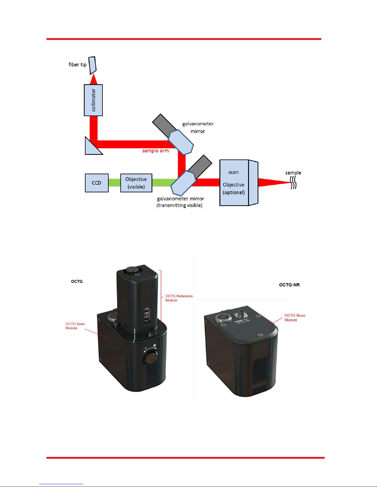
5.2.3. Realization
The basic optical layout of the OCTG scanner in common path layout is illustrated below in Figure 7.
Figure 7 Optical Layout OCTG
The output of an FC/APC fiber is collimated and routed to a beam splitter cube. Here the beam is divided
into a sample beam and a reference beam, similar to a Michelson interferometer. The sample beam is
routed over two galvanometer actuated mirrors to allow for scanning in two axes. The scan objective then
focuses the beam in the sample. Back-scattered and back-reflected light is collected by the scan objective
again and travels back to the fiber. The light reflected into the reference arm is retro-reflected back into the
fiber. There is an optimum intensity for the reference light that can be adjusted using the reference intensity
adjustment knob which will open or close the variable aperture inside the OCTG.
OCTG Series Scanner Chapter 5: Description
Page 12 MTN004419-D02
In the dual path configuration of the OCTG-NR, the reference path components are not included.
Figure 8 Optical Layout OCTG Common Path
5.3. Components
The OCTG Standard Scanner are to be used in combination with Thorlabs’ OCT base units.
Figure 9 OCT Modules OCTG and OCTG-NR
OCTG Series Scanner Chapter 5: Description
Rev C, April 06, 2016 Page 13
The major components of the OCTG Standard Scanner are an OCTG base module and a
Reference Arm Module if applicable. We recommend also considering other accessories like the OCT-LKx
scan lens kit and the OCT-RAx reference arm adapter.
The following sections describe the two modules and possible accessories in detail.
ATTENTION
Always turn off the light source before changing or adjusting OCTG configuration or
accessories such as the objective, scan lens kit, reference arm adapter, or sample z-spacer.
For Thorlabs OCT base units, turn off the OCT base unit main power to turn off the light
source.
Please contact a member of the Thorlabs’ OCT support team to determine if other parts you wish to use are
compatible (see Chapter 11). Any modification or servicing of this system by unqualified personnel renders
the warranty null and void, leaving Thorlabs free of any liability.
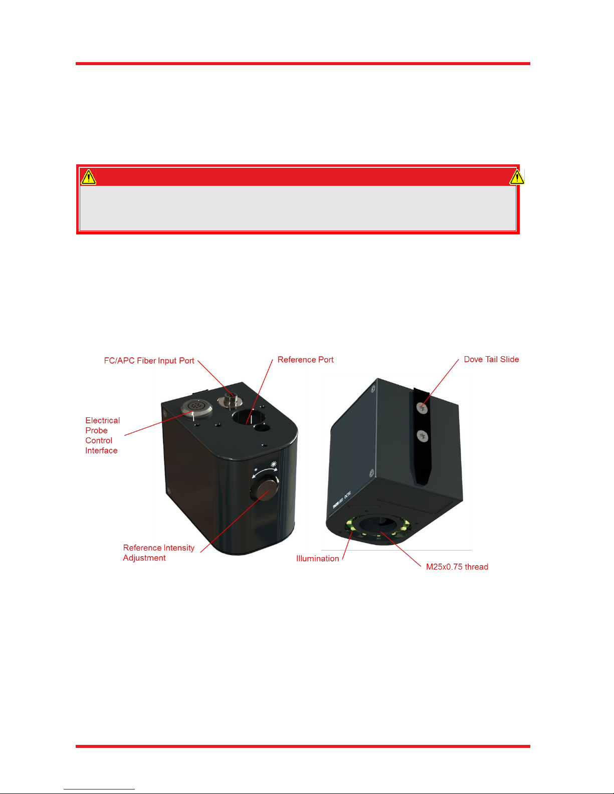
5.3.1. OCTG Base Module
The OCTG base module provides high-speed, two-dimensional (X and Y) raster scans of the specimen. The
clear aperture of the scan mirrors used within is Ø 6 mm. The module also contains a high-resolution video
camera for recording the sample during the measurement.
Figure 10 OCT Base Module
The electrical control interface hosts the included Thorlabs electric control cable to connect the scanner with
a Thorlabs OCT base unit. Please contact Thorlabs’ OCT support (see Chapter 11) for information regarding
the pin configuration.
The optical fiber port is a FC/APC receptacle.
The optical output to the reference arm is equipped with a circular iris aperture which is manipulated using
the reference adjustment knob. In order to adjust the reference intensity, it may be necessary to rotate the
reference length adjustment knob. Rotating clock-wise increases the reference intensity, rotating counter
clock-wise decreases it.

OCTG Series Scanner Chapter 5: Description
Page 14 MTN004419-D02
ATTENTION
The iris aperture might be damaged by inadequate torque. In positions “open” and “closed”
an enlarged mechanical resistance indicates the limit of the travel range.
In order to adjust the reference intensity adjustment knob, pull the knob approximately 5 mm outwards until
you feel the knob coming to a rest.
Figure 11 Reference Intensity Adjustment
As a qualitative indication, observe the reference intensity bar in the OCT software. Please refer to the
Software Manual for additional guidance.
OCTG Series Scanner Chapter 5: Description
Rev C, April 06, 2016 Page 15
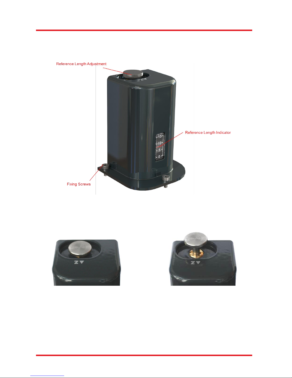
5.3.2. OCTG Reference Module
The reference module contains a mounted mirror (i.e., retro reflector) that reflects the beam from the light
source back into the OCT interferometer.
Figure 12 OCTG Reference Module
In order to match the optical path length in this reference arm to the optical path length of the light from the
sample, it may be necessary to translate the mirror along the axis of the optical system. Length adjustments
can be performed by rotating the reference length adjustment knob.
Figure 13 Reference Length Adjustment
Rotating clock-wise increases the reference path length, rotating counter clockwise reduces it.
The position of the mirror can be monitored using the reference length indicator on the front side of the module.
The full adjustment range of the reference module is >12 mm while the intended standard position is around
3 mm giving an adjustment range of -2 mm / +10 mm.
locked
unlocked
OCTG Series Scanner Chapter 5: Description
Page 16 MTN004419-D02
5.3.3. OCT Scan Lens Kit (Accessory)
The OCT scan lens kit from Thorlabs are specially designed accessories to support telecentric scanning over
a wide range and to compensate the dispersion mismatch of the scanner. The OCT-LKx are fully compatible
with the OCTG.
If you ordered a scan lens kit and reference adapter with the OCTG, these items are pre-installed.
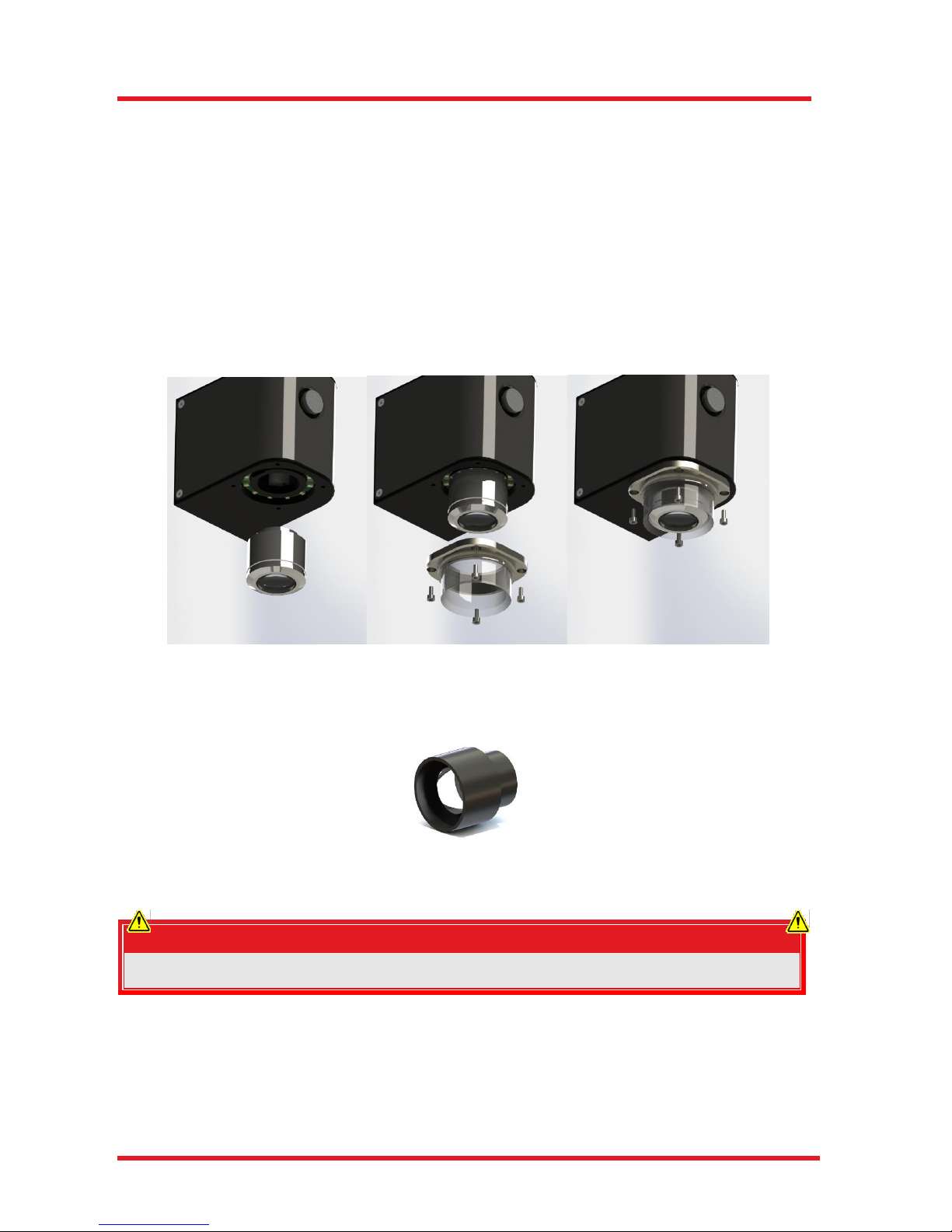
If not already installed the installation procedure follows these three steps.
Insert the included OCT scan lens by screwing it in,
Inserting the illumination module
Secure the illumination module using the four included M2.5x6 cap screws
Figure 14 Installation of Scan Objective and Illumination
Another part of the lens kit is the dispersion compensation set. This has to be inserted into the
reference adapter OCT-RAx
Figure 15 Dispersion Compensation Set
ATTENTION
Optics are sensitive components!
When handling the objective lens take care to avoid touching or harming the optical surfaces.
Changing the objective of the OCTG requires changing the probe configuration data in the software package
ThorImage OCT as well.
This is performed automatically using the calibration procedure built-in the ThorImage OCT Software package
version 4.1.4 and higher. A detailed description of this procedure is given in the ThorImage OCT Operating
Manual.
OCTG Series Scanner Chapter 5: Description
Rev C, April 06, 2016 Page 17
5.3.4. Reference Arm Adapter (Accessory)
The match the required optical path length and the dispersion for the used OCT scan lens kit the installation
of the reference arm adapter OCT-RAx is strongly suggested.
If you ordered a reference arm adapter with the OCTG, this item is pre-installed.
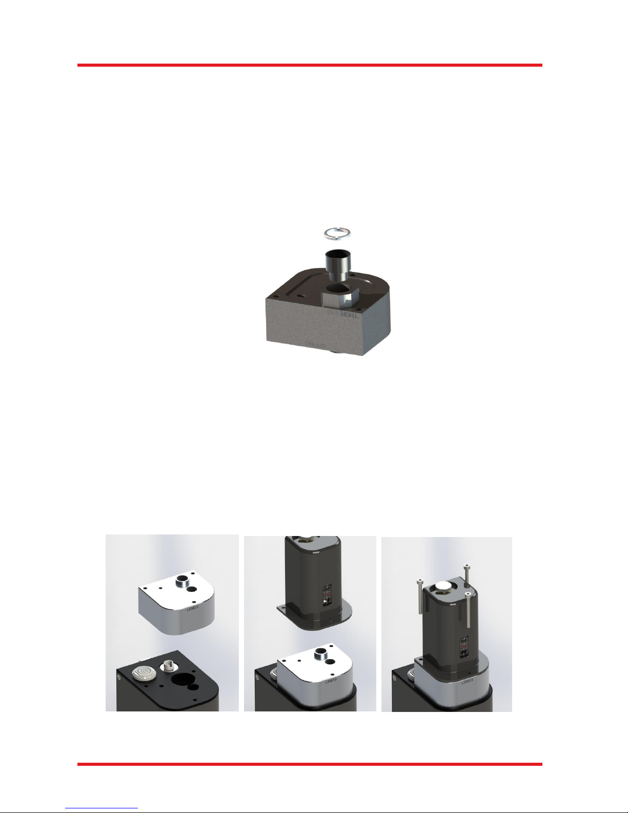
If not already installed the dispersion compensation kit provided with the lens kit and must be installed
Insert the dispersion compensation kit, which is part of the lens kit, into the reference adapter
Fix it using the SM05 retaining ring
Figure 16 Installation of Dispersion Compensation Set
For the installation procedure of the OCT-RAx follow these steps.
Remove the OCT reference module by loosen the three fixed M3x6 cap screws
Insert the reference arm adapter onto the OCT base module
Inserting the OCT reference module onto the reference arm adapter
Secure the assembly using the three included M3 cap screws
Figure 17 Installation of Reference Arm Adapter
OCTG Series Scanner Chapter 5: Description
Page 18 MTN004419-D02
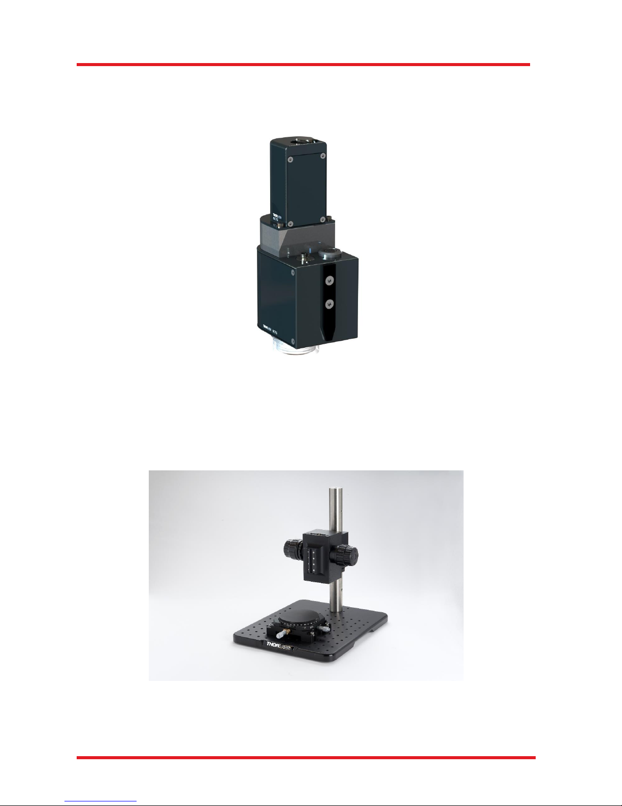
5.3.5. Dove Tail Mount
The OCTG ships with a dovetail mount at the back side (as seen in Figure 18 below). This accessory allow
the scanner to be mounted in standard Thorlabs OCT-Stand.
Figure 18 OCTG-1300 with Dove Tail Mount
The OCT-Stand is a dedicated stand for OCTG scanners.
The OCTG scanners are attached to the focus block of the OCT-Stand using a spring loaded mount accepting
the dove tail mount of the OCTG. The focus block can be rotated 360° around the Ø1.5” rod, and features
30 mm of travel with fine and coarse adjustment knobs.
Figure 19 OCT Stand with OCT-XYR1
OCTG Series Scanner Chapter 5: Description
Rev C, April 06, 2016 Page 19
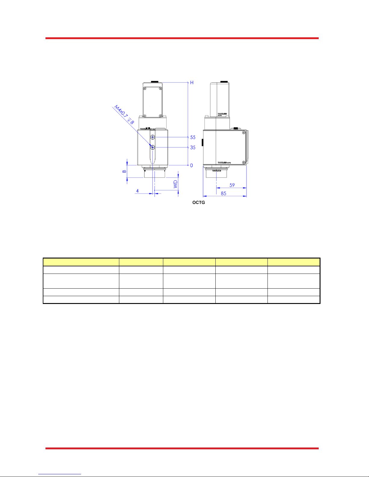
5.4. Dimensions
The dimensions of the OCTG series standard scanners are given in the following drawing. All dimensions are
in mm.
Figure 20 Drawing showing Dimensions,
Mounting Options, and Focal Plane
The opto-mechanical specifications of the OCT scan lens kits are listed in the table below.
Scan Lens Kit #
No OCT-LK
OCT-LK2 (-BB)
OCT-LK3 (-BB)
OCT-LK4 (-BB)
Field of View
-
6 mm x 6 mm
10 mm x 10 mm
16 mm x 16 mm
Mechanical Height (H)
OCTG
139 mm /
71.5 mm
142.5 mm /
71.5 mm
162 mm /
71.5 mm
189 mm /
71.5 mm
Barrel Height (B)
-
25.5 mm
24.0 mm
37.0 mm
Working Distance (WD)
-
3.4 mm
24.9 mm
41.6 mm
Table 2 Data for OCT Scan Lens Kits
Changing the objective of the OCTG requires changing the probe configuration data in the software package
ThorImage OCT as well.
This is performed automatically using the calibration procedure built-in the ThorImage OCT software package
version 4.1.4 and higher. A detailed description of this procedure is given in the ThorImage OCT operating
manual.

OCTG Series Scanner Chapter 6: Troubleshooting
Page 20 MTN004419-D02
Chapter 6 Troubleshooting
Problem
Possible Cause
Recommended Solution
Poor Reference
Light Intensity
Fiber Not Connected
Remove and Reconnect Fiber, Ensuring that
Alignment Key is Inserted into Key Slot
Aperture is Too Small
Open Aperture
Fiber Tip is Dirty
Clean Fiber Tip (Thorlabs’ MCC-7020 Fiber
Connector Cleaner Recommended)
Other Reason
Contact OCT Service (See Chapter 11)
No Image is Obtained
Optical Path Length of Reference and
Sample Arms is Not Matched
Adjust Reference Arm Length
Beam is Blocked
Check for Obstructions in Optical Path
USB Cable is Loose
Reconnect USB Cable
PC Crashed
Restart PC
Other Reason
Contact OCT Service (See Chapter 11)
Low Scan Resolution
Dispersion in Reference and Sample
Arms is Not Matched
Check if Dispersion compensation is installed
Bad Image Quality
Image Obtained is Being Mirrored
Adjust the Distance Between the Objective and
the Sample. The Image Should Move Towards
the Top of the Computer Window
Optical Path Length of Sample Arm
is Too Short
Move Sample Away From Objective
Reference Intensity is Too High
or Too Low
Close or Open Aperture Iris to Adjust Intensity
Other Reason
Contact OCT Service (See Chapter 11)
Flipped Image
Optical Path Length of Reference Arm
is Incorrect
Adjust Reference Arm Length
Table 3 Troubleshooting
OCTG Series Scanner Chapter 7: Certifications and Compliance
Rev C, April 06, 2016 Page 21
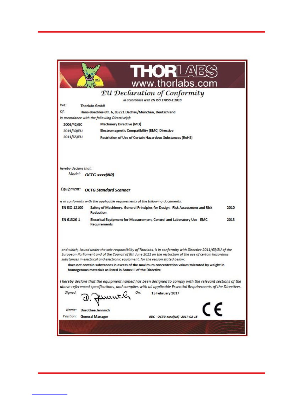
Chapter 7 Certifications and Compliance

OCTG Series Scanner Chapter 8: Specifications
Page 22 MTN004419-D02
Chapter 8 Specifications
OCTG
Optical Specifications
Center Wavelength
900 nm, or 1300 nm
Clear Aperture
Ø6 mm (Max)
Reference Length Fine Adjustment
-2 mm / +10 mm
Scan Distance (Objective Shoulder)
15.0 mm / 28 mm
General Specifications
Video Camera
Color CMOS
Weight of Scanner
1 kg (2.2 lbs)
Storage / Operating Temperature
10 °C to 35 °C
Dimensions of OCTG (L x W x H)
85 mm x 60 mm x 139 mm
Dimensions of OCTG-NR (L x W x H)
85 mm x 60 mm x 71 mm
Airborne Noise Emission
< 70 dBA
Table 4 Specifications OCTG
OCT Scan Lens Kits
Objective Item #
OCT-LK2(-BB)
OCT-LK3(-BB)
OCT-LK4(-BB)
Field of View
6 mm x 6 mm
10 mm x 10 mm
16 mm x 16 mm
Barrel Height (B)
25.5 mm
24.0 mm
37.0 mm
Working Distance
3.4 mm
24.9 mm
41.6 mm
Table 5 Specifications Scan Lens Kits

OCTG Series Scanner Chapter 8: Specifications
Rev C, April 06, 2016 Page 23
8.1. Reflectivity Scanning Mirror
The OCTG series standard scanners are equipped with a semitransparent galvo mirror to enable video
camera imaging.*
Figure 21 Reflectivity of Scanning Mirroor
* In systems delivered prior to February 2017 a coating with different characteristics was used. For further
information about their performance, please contact Thorlabs’ OCT support (see Chapter 11).
90
95
100
800 900 1000 1100 1200 1300 1400 1500
Reflectivity(%)
Wavelength (nm)
OCTG Mirror 45°
S-Pol.
Unpolarized
P-Pol.

OCTG Series Scanner Chapter 9: Warranty
Page 24 MTN004419-D02
Chapter 9 Warranty
9.1. Imaging Systems
Thorlabs offers a one-year warranty on the OCTG standard scanner.
9.2. Non-Warranty Repairs
Products returned for repair that are not covered under warranty will incur a standard repair charge in addition
to all shipping expenses. This repair charge will be quoted to the customer before the work is performed.
9.3. Warranty Exclusions
The stated warranty does not apply to products which are (a) specials, modifications, or customized items
(including custom patch cables) meeting the specifications you provide; (b) ESD sensitive items whose static
protection packaging has been opened; (c) items repaired, modified, or altered by any party other than
Thorlabs; (d) items used in conjunction with equipment not provided by or acknowledged as compatible by
Thorlabs; (e) subjected to unusual physical, thermal, or electrical stress; (f) damaged due to improper
installation, misuse, abuse, or storage; (g) damaged due to accident or negligence in use, storage,
transportation, or handling.

OCTG Series Scanner Chapter 10: Regulatory
Rev C, April 06, 2016 Page 25
Chapter 10 Regulatory
As required by the WEEE (Waste Electrical and Electronic Equipment Directive) of the European Community
and the corresponding national laws, Thorlabs offers all end users in the EC the possibility to return “end of
life” units without incurring disposal charges.
This offer is valid for Thorlabs electrical and electronic equipment:
Sold after August 13, 2005
Marked correspondingly with the crossed out “wheelie bin” logo (see right)
Sold to a company or institute within the EC
Currently owned by a company or institute within the EC
Still complete, not disassembled and not contaminated
As the WEEE directive applies to self-contained operational electrical and electronic products, this end of life
take back service does not refer to other Thorlabs products, such as:
Pure OEM products, that means assemblies to be built into a unit by the user (e. g. OEM laser driver
cards)
Components
Mechanics and optics
Left over parts of units disassembled by the user (PCB’s, housings etc.).
If you wish to return a Thorlabs unit for waste recovery, please contact Thorlabs or your nearest dealer for
further information.
10.1. Waste Treatment is Your Own Responsibility
If you do not return an “end of life” unit to Thorlabs, you must hand it to a company specialized in waste
recovery. Do not dispose of the unit in a litter bin or at a public waste disposal site.
10.2. Ecological Background
It is well known that WEEE pollutes the environment by releasing toxic products during decomposition. The
aim of the European RoHS directive is to reduce the content of toxic substances in electronic products in the
future.
The intent of the WEEE directive is to enforce the recycling of WEEE. A controlled recycling of end of life
products will thereby avoid negative impacts on the environment.
Wheelie Bin Logo

OCTG Series Scanner Chapter 11: Thorlabs OCT Support Contact
Page 26 MTN004419-D02
Chapter 11 Thorlabs OCT Support Contact
If you have a technical question or issue on Thorlabs OCT products, please refer directly to the OCT Support
team located in Luebeck, Germany.
OCT Support
Thorlabs GmbH
Maria-Goeppert-Straße 9
23562 Lübeck
Germany
Tel: +49-(0)8131-5956-0
Fax: +49-(0)8131-5956-99
www.thorlabs.de
Email: oct-support@thorlabs.com

OCTG Series Scanner Chapter 12: Thorlabs Worldwide Contacts
Rev C, April 06, 2016 Page 27
Chapter 12 Thorlabs Worldwide Contacts
USA, Canada, and South America
Thorlabs, Inc.
56 Sparta Avenue
Newton, NJ 07860
USA
Tel: 973-300-3000
Fax: 973-300-3600
www.thorlabs.com
www.thorlabs.us (West Coast)
Email: sales@thorlabs.com
Support: techsupport@thorlabs.com
UK and Ireland
Thorlabs Ltd.
1 Saint Thomas Place
Ely CB7 4EX
Great Britain
Te
l: +44
(0) 1353-654440
Fax: +44 (0) 1353-654444
www.thorlabs.com
Email: sales.uk@thorlabs.com
Support: techsupport.uk@thorlabs.com
Europe
Thorlabs GmbH
Hans-Böckler-Str. 6
85221 Dachau
Germany
Tel: +49-(0) 8131-5956-0
Fax: +49-(0) 8131-5956-99
www.thorlabs.de
Email: europe@thorlabs.com
Scandinavia
Thorlabs Sweden AB
Bergfotsgatan 7
431 35 Mölndal
Sweden
Tel: +46-31-733-30-00
Fax: +46-31-703-40-45
www.thorlabs.com
Email: scandinavia@thorlabs.com
France
Thorlabs SAS
109, rue des Côtes
78600 Maisons-Laffitte
France
Tel: +33 (0) 970 444 844
Fax: +33 (0) 825 744 800
www.thorlabs.com
Email: sales.fr@thorlabs.com
Brazil
Thorlabs Vendas de Fotônicos Ltda.
Rua Riachuelo, 171
São Carlos, SP 13560-110
Brazil
Tel: +55-16-3413 7062
Fax: +55-16-3413 7064
www.thorlabs.com
Email: brasil@thorlabs.com
Japan
Thorlabs Japan, Inc.
3-6-3 Kitamachi,
Nerima-ku, Tokyo 179-0081
Japan
Tel: +81-3-6915-7701
Fax: +81-3-6915-7716
www.thorlabs.co.jp
Email: sales@thorlabs.jp
China
Thorlabs China
Room A101, No. 100, Lane 2891
South Qilianshan Road
Putuo District
Shanghai
China
Tel: +86 (0) 21-60561122
Fax: +86 (0) 21-32513480
www.thorlabschina.cn
Email: chinasales@thorlabs.com

M0009-510-885-D
www.thorlabs.com
 Loading...