

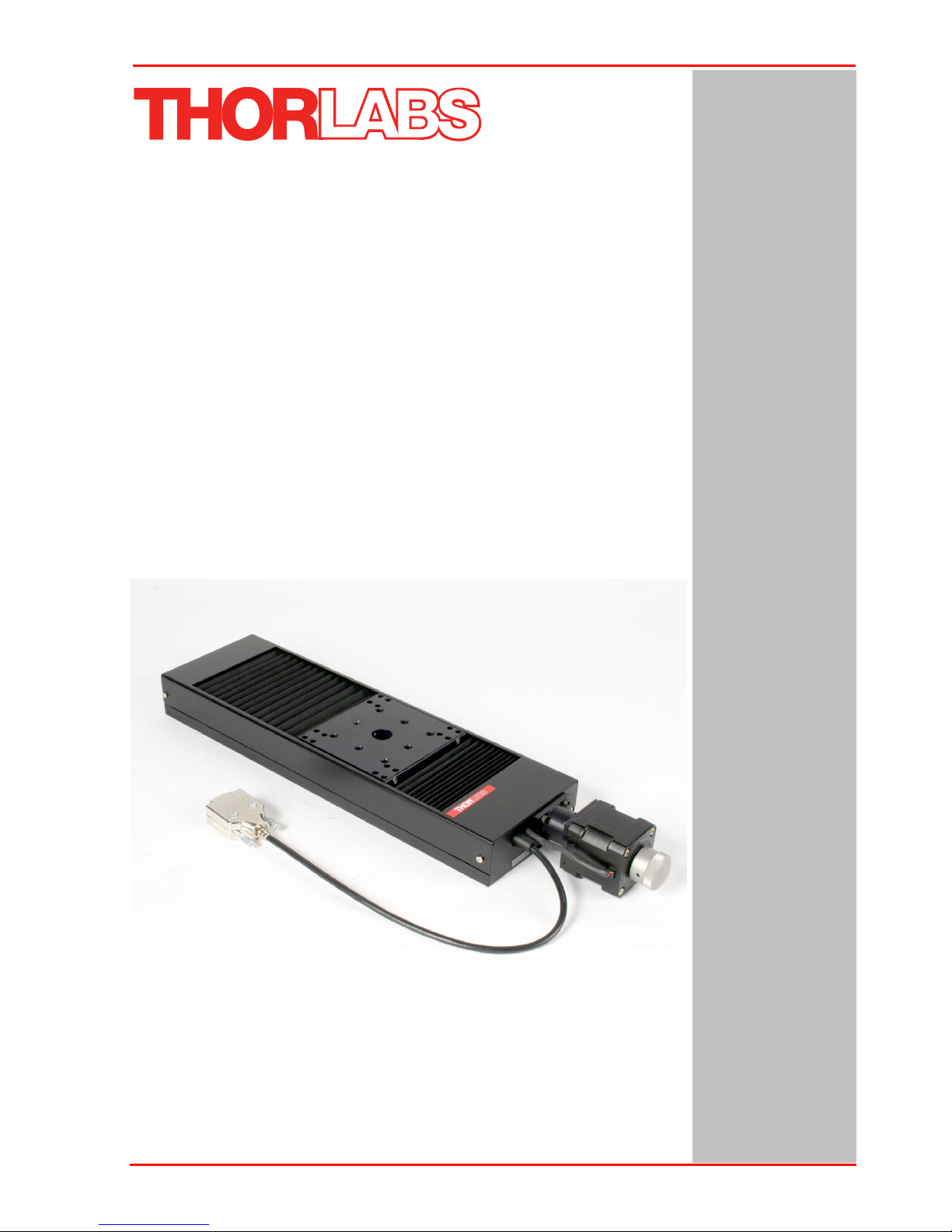
NRT Series
Motorized Translation Stage
User Guide
Original Instructions
HA0136T

NRT Series Motorized Translation Stages
Contents
Chaper 1 Introduction .................................................................................................1
Chaper 2 Safety ...........................................................................................................2
2.1 Safety Information ..............................................................................2
2.2 General Warnings and Cautions .......................................................2
Chaper 3 Installation and Operation .........................................................................3
3.1 Mounting to a Work Surface ..............................................................3
3.1.1 General ................................................................................................... 3
3.2 Environmental Conditions .................................................................3
3.2.1 Mounting a Single Stage to a Work Surface ........................................... 4
3.2.2 Mounting stages in X-Y configurations ................................................... 5
3.2.3 Mounting stages in X-Y-Z configurations ................................................ 6
3.3 Operation .............................................................................................8
3.3.1 System Setup ......................................................................................... 8
3.3.2 Selecting the Stage Type ....................................................................... 8
3.4 Calibration of Motor Drives ..............................................................11
3.5 Maintenance ......................................................................................11
Chaper 4 Specification .............................................................................................12
4.1 Specification .....................................................................................12
4.2 Pin Out ...............................................................................................13
4.3 Parts List ...........................................................................................13
Chaper 5 Regulatory .................................................................................................14
5.1 Declarations Of Conformity .............................................................14
5.1.1 For Customers in Europe ...................................................................... 14
5.1.2 For Customers In The USA .................................................................. 14
Chaper 6 CE Certificate .............................................................................................15
Chaper 7 Thorlabs Worldwide Contacts .................................................................17
Page 0
Chapter 1 Overview
Chapter 1 Overview
1.1 Introduction
The NRT series stages are performance positioning stages which are ideally suited
for measurement and inspection applications. The main platform is supported by 4
recirculating ball carrier bearings mounted to precisely aligned linear guide rails. A
backlash free precision lead screw produces smooth translation, directly driven with
a hybrid 2-phase stepper motor capable of 409,600 micro steps per revolution, and
positioning resolutions of less than 100nm when driven by the BSC series of benchtop
controllers. The highly repeatable, Hall effect (magnetic) home detection limit switch
also provides overdriving protection in both forward and reverse directions.
The high quality stepper motor offers excellent dynamic and static torque
performance and the design provides the detailed features required of any true
nanopositioning product.
Rev 12 Oct 2018
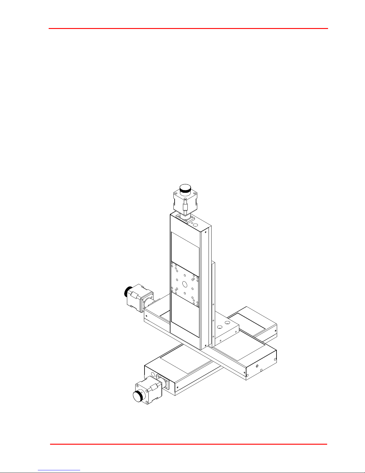
Fig. 1.1 Typical XYZ Configuration
Page 1
NRT Series Motorized Translation Stages
Chapter 2 Safety
2.1 Safety Information
For the continuing safety of the operators of this equipment, and the protection of the
equipment itself, the operator should take note of the Warnings, Cautions and Notes
throughout this handbook and, where visible, on the product itself.
The following safety symbols may be used throughout the handbook and on the
equipment itself.
Warning: Risk of Electrical Shock
Given when there is a risk of injury from electrical shock.
Warning
Given when there is a risk of injury to users.
Caution
Given when there is a risk of damage to the product.
Note
Clarification of an instruction or additional information.
2.2 General Warnings and Cautions
Warning
If this equipment is used in a manner not specified in the handbook, the
protection provided by the equipment may be impaired. In particular, excessive
moisture may impair operation.
Spillage of fluid, such as sample solutions, should be avoided. If spillage does
occur, clean up immediately using absorbant tissue. Do not allow spilled fluid to
enter the internal mechanism.
The equipment is for indoor use only.
When running custom move sequences, or under fault conditions, the stage
may move unexpectedly. Operators should take care when working inside the
moving envelope of the stage.
Page 2
Chapter 3 Installation and Operation
Chapter 3 Installation and Operation
Note
Retain the packing in which the unit was shipped, for use in future transportation.
3.1 Mounting to a Work Surface
3.1.1 General
When mounting the NRT stage close to other equipment, ensure that the travel of the
moving platform is not obstructed. If equipment mounted on the moving platform is
driven against a solid object, damage to the internal mechanism could occur. The
range of travel for each model is as follows:
NRT100 - 100mm, NRT150 - 150mm.
3.2 Environmental Conditions
Warning
Operation outside the following environmental limits may adversely affect
operator safety.
Location Indoor use only
Maximum altitude 2000 m
Temperature range 5
Maximum Humidity Less than 80% RH (non-condensing) at 31°C
To ensure reliable operation the unit should not be exposed to corrosive agents or
excessive moisture, heat or dust.
If the unit has been stored at a low temperature or in an environment of high humidity,
it must be allowed to reach ambient conditions before being powered up.
The unit must not be used in an explosive environment.
o
C to 40oC
Rev 12 Oct 2018
Page 3
NRT Series Motorized Translation Stages
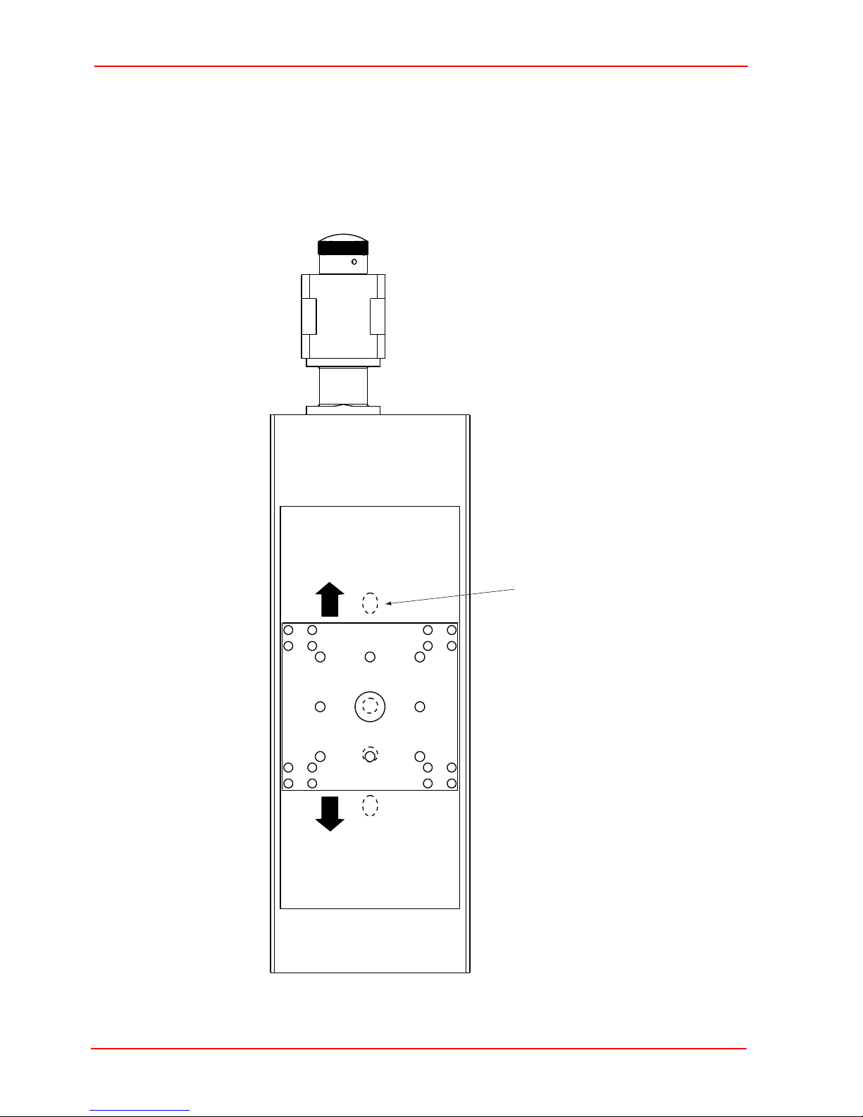
mounting holes thru base
qty 4 NRT100
qty 5 NRT150
3.2.1 Mounting a Single Stage to a Work Surface
The NRT stage is mounted to the working surface by M6 screws through the base. To
access these mounting holes, turn the motor knob to move the carriage until the holes
are visible through the center hole - see Fig. 3.1. The stage can also be mounted in
other orientations - see Section 3.2.2. and 3.2.4
Page 4 14098-D01
Fig. 3.1 Mounting Holes
Chapter 3 Installation and Operation
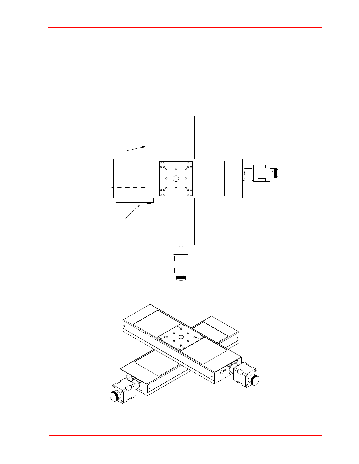
(square)
(flat plate)
3.2.2 Mounting stages in X-Y configurations
Tools required:
5mm hexagon key,
Qty 2, M6 x 12 (1/4-20 UNC x 1/2”) cap head bolts,
Engineers square and a flat plate.
Rev 12 Oct 2018
Fig. 3.2 X-Y configuration
Page 5

NRT Series Motorized Translation Stages
1) Fix the X axis stage to the worksurface, as detailed in Section 3.2.1.
2) Turn the motor knob of the Y axis stage to move the top platform sufficiently to
gain access to the fixing holes in the base plate.
3) Position the stages as shown in Fig. 3.2.
4) Fit and tighten the securing bolts then loosen 1/4 to 1/2 turn.
Caution
Ensure that the screws do not foul the carriage as it moves backwards and
forwards.
5) If all fixing holes cannot be accessed, move the top platform as necessary to gain
access, then repeat items 2) to 5).
6) Position the engineers square and flat plate as shown in Fig. 3.2.
7) Align the stages squarely then tighten the securing bolts.
8) Recheck that the stages are square and readjust as necessary.
3.2.3 Mounting stages in X-Y-Z configurations
1) Fix the X axis stage to the worksurface as detailed in Section 3.2.1.
2) Assemble two stages in an XY configuration as detailed in Section 3.2.2.
3) Fit the Z-bracket assembly (NRT150P1) to the Y axis stage and attach the Z axis
stage as shown in Fig. 3.3.
If accurately square z-axis travel is required, use an engineering square to align the
orthgonality of the z-axis travel by noting the size of the gap between the moving plate
and the square at either end of vertical travel. It there is a noticable difference in the
size of this gap then adjustments should be made through loosening/tightening of the
mounting bracket to the stage:
Page 6 14098-D01

Z bracket assembly
(NRT150P1)
bracket may be turned
through 90° on Y stage
X
Y
Z
Side View
Plan View
Chapter 3 Installation and Operation
Rev 12 Oct 2018
Fig. 3.3 X-Y-Z configuration
Page 7

NRT Series Motorized Translation Stages
3.3 Operation
The NRT stage should be driven by the Thorlabs stepper motor BSC series
controllers - see www.thorlabs.com for further details. The flying lead of the stage is
terminated in a D-type connector - see Chapter 4 for pin out details, and should be
connected to the controller via the extension cable supplied.
Caution
Do not attempt to control this stage using the KST101 or TST101 K-Cube or T-Cube
controllers. There is no software configuration for use with these devices.
The stepper motor controller must be switched OFF before the stages are
plugged in or unplugged. Failure to switch the controller off may result in
damage to either the controller, the stage, or both.
Because it can be software controlled it should be noted that this device could
begin to move unexpectedly for a person within its envelope of operation, who
had not programmed the move. However, max speed and load are such that
risks are minimal.
3.3.1 System Setup
1) Install the electronic hardware and connect the controller to the relevent axes of
the associated stage(s) (see the handbooks supplied with the APT Controllers).
2) For each Stepper Motor Controller in your system, fit the interlock plug (supplied)
to the MOTOR CONTROL connector on the rear panel.
3.3.2 Selecting the Stage Type
To ensure that a particular stage is driven properly by the system, a number of parameters
must first be set. These parameters relate to the physical characteristics of the stage being
driven (e.g. min and max positions, leadscrew pitch, homing direction etc.).
To assist in setting these parameters correctly, it is possible to associate a specific stage
type and axis with the motor controller channel. Once this association has been made, the
server applies automatically, suitable default parameter values on boot up of the software.
Page 8 14098-D01
Chapter 3 Installation and Operation
Using APT Software
3) Shut down all applications using the APT server (e.g. APT User or your own
custom application).
4) Run the APT Config utility - Start/All Programs/Thorlabs/APT Config/APT Config.
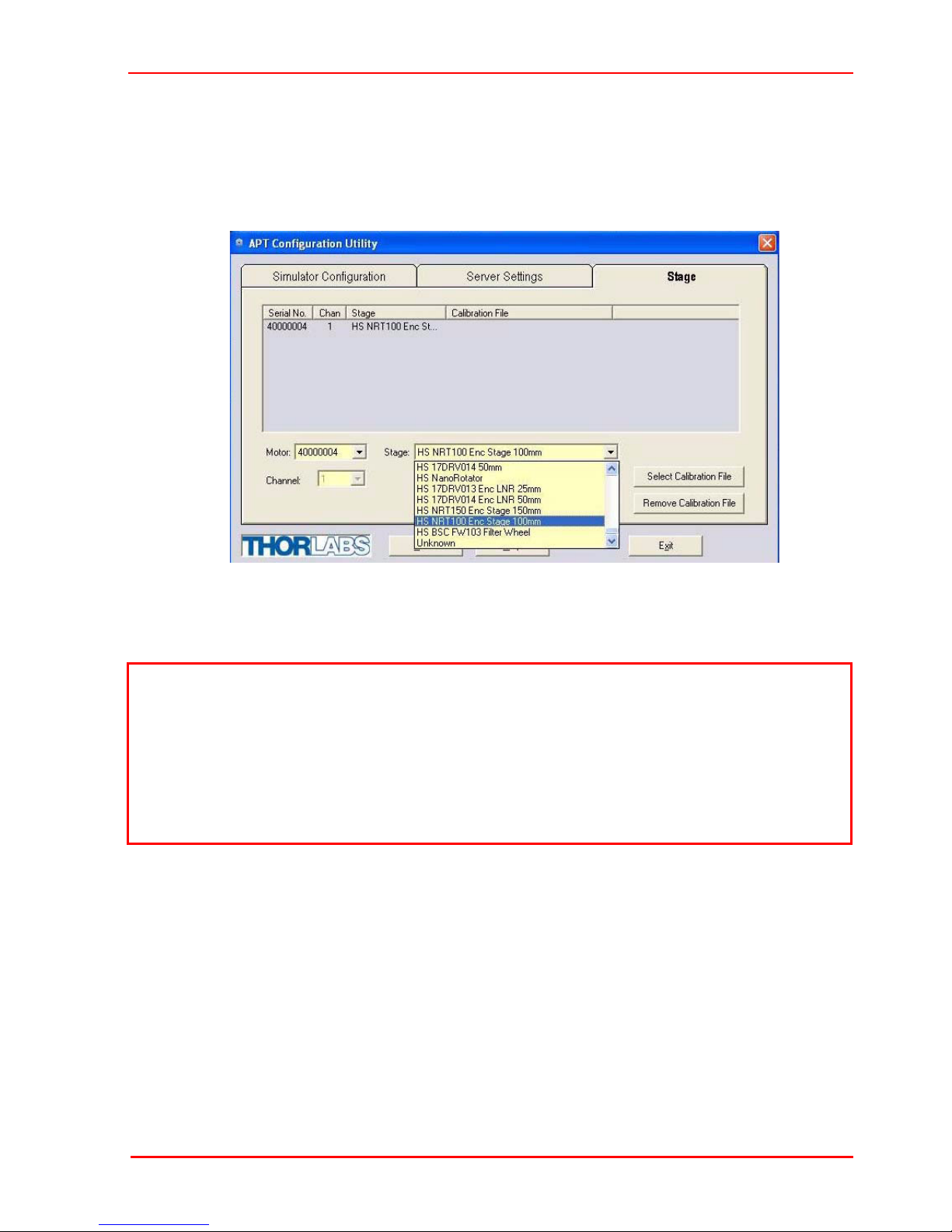
5) From the 'APT Configuration Utility' window, click the 'Stage' tab.
Fig. 3.4 APT Configuration Utility - Stage Tab
6) In the ‘Motor’ field, select the serial number of the stepper motor controller to be
configured (this number can be found on the rear panel of the controller unit).
Note
To ensure correct operation, it is important to select the correct stage type for your
controller. If using a MST602 or BSC20x series controller, select the appropriate ‘HS
NRT xxx Enc’ option. If using a legacy BSC0xx or BSC10x controller, choose an
option without the ‘HS’ prefix.
Selecting an incompatible stage type could result in reduced velocity and resolution
or, when using a joystick, the joystick may be inoperable.
7) In the ‘Stage’ field, select the stage (e.g. ‘HS NRT100 Enc’) from the list displayed.
8) Click the 'Add Stage Association' button.
9) A default configuration is set at the factory and stored in the non-volatile memory
of the motor controller. The server reads in the stage and controller information on
start up.
See the handbook for the associated stepper motor controller for more information
on driving the actuator/stage.
Rev 12 Oct 2018
Page 9

NRT Series Motorized Translation Stages
Using Kinesis Software
1) Ensure that the device is connected to the PC and powered up.
2) Run the Kinesis software - Start/All Programs/Thorlabs/Kinesis/Kinesis.
3) On start-up, the 'Actuator/Startup Settings’ window is displayed. This window
allows the correct actuator to be selected.
4) From the drop down menu, select your NRT stage type (e.g. HS NRT100 Enc
Stage 100mm).
5) Click OK.
6) The server reads in the stage and controller information automatically.
See the handbook for the associated stepper motor controller for more information
on driving the actuator/stage.
Page 10 14098-D01
Fig. 3.5 Stage Configuration Window

Chapter 3 Installation and Operation
3.4 Calibration of Motor Drives
Calibration enables the server to correct for any mechanical errors inherent in the
system. Mechanical components, such as the leadscrew and linkages, can be machined
only within a certain tolerance, e.g. the leadscrew may be nominally 1mm but actually
1.0005mm, giving a 0.5 micron error. In practice, these errors accumulate from a number
of sources, however they are repeatable and therefore, can be compensated.
During calibration, the total positional error is measured at a large number of points
and these errors are stored as a look up table (LUT). The LUT is saved as a
calibration file, one file for each axis on a particular stage. These files are then linked
to the appropriate axis as part of the Stage association process performed using the
APT Config utility. Whenever the stage is moved, the LUT is consulted to ascertain
the precise movement required to achieve the demanded position.
The use of a calibration file is optional. Without it, the repeatability and resolution of
the stage are unaffected, but no compensations are made to enhance the accuracy.
Calibration files can be downloaded from the support documents section on the
product web page, one file for each serial number. Details on assigning a calibration
file are contained in the APTConfig On Line Helpfile.
3.5 Maintenance
The unit contains no user servicable parts and must be returned to the manufacturer
for service and/or repair.
Caution
When packing the unit for shipping, use the original packing. If this is not
available, use a strong box and surround the unit with at least 100 mm of shock
absorbent material.
Rev 12 Oct 2018
Page 11

NRT Series Motorized Translation Stages
Chapter 4 Specification
4.1 Specification
Specification NRT100 NRT150
Travel Range 100 mm 150 mm
Load Capacity 20 kg Horizontal
5.0 kg Vertical
Bidirectional Repeatability 1.0 µm
Max Load Capacity 21.8 kg (48 lbs)
Velocity Range* 40.0 µm/s to 30 mm/s
Acceleration 30 mm/s/s
Min Achievable Incremental Movement 0.1 µm
Absolute On-Axis Accuracy 15.29 µm 19.29 µm
Calibrated On-Axis Accuracy 2.0 µm 2.0 µm
Pitch 0.008° (140 µrad)
Yaw 0.05° 873 µrad
Operating Temperature -20µ to +40 µ C
Weight 2.2 kg (4.8 lb) 2.5 kg (5.5 lb)
Construction Aluminum with precision, recirculating linear
bearings
Full Step Angle 1.8°
Step Angle Accuracy 5%
Rated Phase Current 1 A
Phase Resistance 4.6 Ω
Phase Inductance 10.6 mH
Holding Torque 23.1 N•cm
Detent Torque 1.7 N•cm
Rotor Inertia 32 g•cm2
Insulation Class B
Limit Switches Ceramic-Tipped Mechanical
Microsteps per Revolution of Leadscrew 409,600
Motor Type 2-Phase Stepper
Compatible Controllers BSC201, MST602
* The velocity quoted above is only achievable with light loads. When using heavy
loads, the velocity should be reduced accordingly.
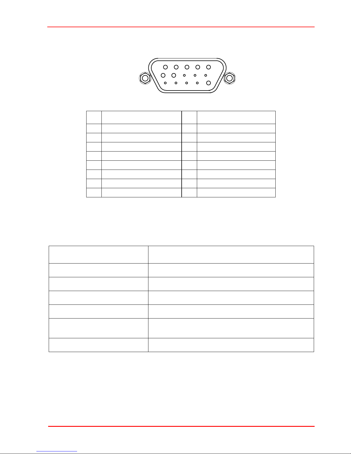
4.2 Pin Out
Page 12
Chapter 4 Specification
5
10
11
15
6
1
The ‘Motor’ connector provides connection to the stepper motor controller. The pin
functions are detailed in Fig. 4.1.
Pin Description Pin Description
1 Limit Switch Ground 9
2 Forward Limit Switch 10
3 Reverse Limit Switch 11
4 Phase B -ve 12
5 Phase B +ve 13 Limit Switch 5V
6 Phase A -ve 14
7 Phase A +ve 15 Ground
8
Fig. 4.1 Motor Connector Pin Descriptions
4.3 Parts List
Part Number Description
PAA612 Connection Cable 1 m (3.3’)
PAA613 Connection Cable 3 m (9.8’)
NRT100 and NRT100/M NanoStep NRT stage with 100mm travel
NRT150 and NRT150/M NanoStep NRT stage with 150mm travel
NRT150P1 ‘Z’ bracket for fixing stages in X-Z, Y-Z and X-Y-Z
configurations
ha0136T Handbook
Rev 12 Oct 2018
Page 13

NRT Series Motorized Translation Stages
Chapter 5 Regulatory
5.1 Declarations Of Conformity
5.1.1 For Customers in Europe
See Section 5.2.
5.1.2 For Customers In The USA
This equipment has been tested and found to comply with the limits for a Class A
digital device, persuant to part 15 of the FCC rules. These limits are designed to
provide reasonable protection against harmful interference when the equipment is
operated in a commercial environment. This equipment generates, uses and can
radiate radio frequency energy and, if not installed and used in accordance with the
instruction manual, may cause harmful interference to radio communications.
Operation of this equipment in a residential area is likely to cause harmful interference
in which case the user will be required to correct the interference at his own expense.
Changes or modifications not expressly approved by the company could void the
user’s authority to operate the equipment.
Page 14
5.2 CE Certificate
Chapter 5 Regulatory
Rev 12 Oct 2018
Page 15
NRT Series Motorized Translation Stages
Page 16 14098-D01

Chapter 6 Thorlabs Worldwide Contacts
USA, Canada, and South America
Thorlabs, Inc.
56 Sparta Avenue
Newton, NJ 07860
USA
Tel: 973-300-3000
Fax: 973-300-3600
www.thorlabs.com
www.thorlabs.us (West Coast)
Email: sales@thorlabs.com
Support: techsupport@thorlabs.com
Europe
Thorlabs GmbH
Hans-Böckler-Str. 6
85221 Dachau
Germany
Tel: +49-(0)8131-5956-0
Fax: +49-(0)8131-5956-99
www.thorlabs.de
Email: europe@thorlabs.com
France
Thorlabs SAS
109, rue des Côtes
78600 Maisons-Laffitte
France
Tel: +33 (0) 970 444 844
Fax: +33 (0) 825 744 800
www.thorlabs.com
Email: sales.fr@thorlabs.com
Japan
Thorlabs Japan, Inc.
3-6-3 Kitamachi,
Nerima-ku, Tokyo 179-0081
Japan
Tel: +81-3-6915-7701
Fax: +81-3-6915-7716
www.thorlabs.co.jp
Email: sales@thorlabs.jp
UK and Ireland
Thorlabs Ltd.
1 Saint Thomas Place, Ely
Cambridgeshire CB7 4EX
Great Britain
Tel: +44 (0)1353-654440
Fax: +44 (0)1353-654444
www.thorlabs.de
email: sales@uk.thorlabs.com
Support: techsupport.uk@thorlabs.com
Scandinavia
Thorlabs Sweden AB
Bergfotsgatan 7
431 35 Mölndal
Sweden
Tel: +46-31-733-30-00
Fax: +46-31-703-40-45
www.thorlabs.com
Email: scandinavia@thorlabs.com
Brazil
Thorlabs Vendas de Fotônicos Ltda.
Rua Riachuelo, 171
São Carlos, SP 13560-110
Brazil
Tel: +55-16-3413 7062
Fax: +55-16-3413 7064
www.thorlabs.com
Email: brasil@thorlabs.com
China
Thorlabs China
Room A101, No. 100
Lane 2891, South Qilianshan Road
Putuo District
Shanghai
China
Tel: +86 (0) 21-60561122
Fax: +86 (0)21-32513480
www.thorlabschina.cn
Email: chinasales@thorlabs.com
Chapter 6 Thorlabs Worldwide Contacts
Thorlabs verifies our compliance with the WEEE (Waste Electrical and Electronic
Equipment) directive of the European Community and the corresponding national
laws. Accordingly, all end users in the EC may return "end of life" Annex I category
electrical and electronic equipment sold after August 13, 2005 to Thorlabs, without
incurring disposal charges. Eligible units are marked with the crossed out "wheelie
bin" logo (see right), were sold to and are currently owned by a company or institute
within the EC, and are not dissembled or contaminated. Contact Thorlabs for more
information. Waste treatment is your own responsibility. "End of life" units must be
returned to Thorlabs or handed to a company specializing in waste recovery. Do not
dispose of the unit in a litter bin or at a public waste disposal site.
Rev 12 Oct 2018
Page 17

www.thorlabs.com
 Loading...