

Page 1
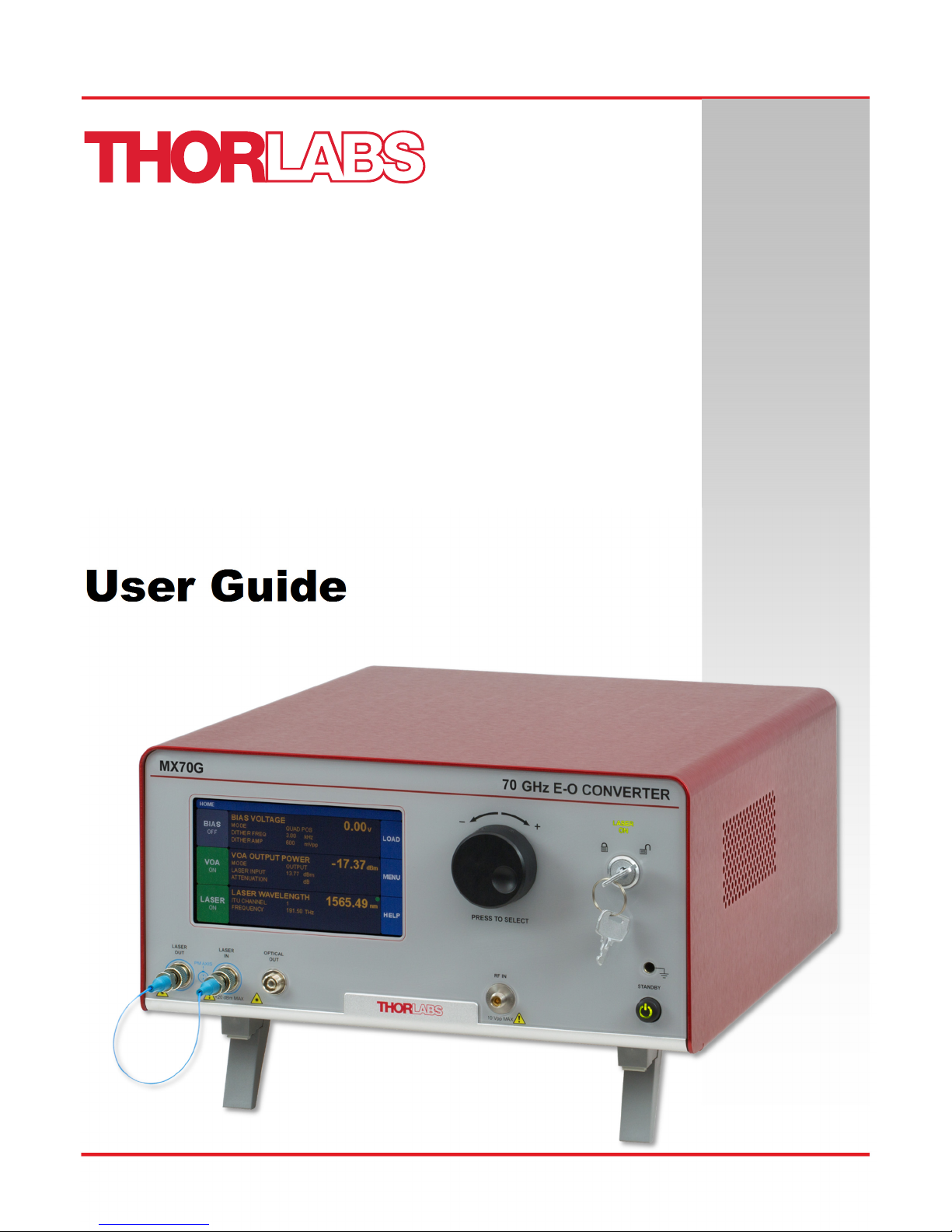
MX40G Series
40 GHz E-O Converters
MX70G Series
70 GHz E-O Converters
User Guide
Page 2

Page 3

MX40G, MX70G Series of E-O Converters
Table of Contents
Chapter 1Introduction .............................................................................................................................................................. 1
1.1 Description ..................................................................................................................................................... 1
1.2 Parts List ........................................................................................................................................................ 1
1.3 Block Diagram................................................................................................................................................ 2
1.4 Front and Back Panel Overview ................................................................................................................... 3
Chapter 2Safety......................................................................................................................................................................... 5
Chapter 3Quick Start Guide ..................................................................................................................................................... 7
3.1 Hardware Set Up ............................................................................................................................................ 7
3.2 Controls on the Home Page .......................................................................................................................... 8
3.3 System Wavelength Setting .......................................................................................................................... 9
3.4 Controls on the Settings Pages .................................................................................................................. 10
3.5 Quick Start ................................................................................................................................................... 11
Chapter 4Operating Instructions ........................................................................................................................................... 12
4.1 The Modulator Transmission Function ...................................................................................................... 12
4.2 De-Embedding Procedures ......................................................................................................................... 12
4.3 Control Loop Diagram ................................................................................................................................. 13
4.4 Bias Settings Page ...................................................................................................................................... 14
4.4.1 Quadrature Mode .............................................................................................................................. 15
4.4.2 Peak Mode ........................................................................................................................................ 17
4.4.3 Null Mode .......................................................................................................................................... 17
4.4.4 Manual Mode .................................................................................................................................... 18
4.5 Variable Optical Attenuator Settings Page ................................................................................................ 20
4.6 Laser Settings Page .................................................................................................................................... 22
4.7 Load Page .................................................................................................................................................... 24
4.8 Menu Page .................................................................................................................................................... 25
4.8.1 System Wavelength .......................................................................................................................... 25
4.8.2 Display and Sound Settings Page ..................................................................................................... 26
4.8.3 System Information Page .................................................................................................................. 26
4.8.4 Accent LED Settings Page ................................................................................................................ 27
4.8.5 Thorlabs Help Page .......................................................................................................................... 27
Chapter 5Specifications ......................................................................................................................................................... 28
5.1 General System Specifications .................................................................................................................. 28
5.2 Power and Environmental Specifications ................................................................................................. 29
5.3 Internal Control Specifications ................................................................................................................... 29
5.4 Internal Modulator Specifications .............................................................................................................. 29
5.5 Laser Specifications .................................................................................................................................... 30
Chapter 6Control and PC Connections ................................................................................................................................. 31
6.1 General Purpose I/O, RS-232, and USB Connections ............................................................................... 31
6.2 The Laser Safety Interlock .......................................................................................................................... 32
Chapter 7Mechanical Drawings ............................................................................................................................................. 33
Chapter 8Maintenance, Repair, and Fuses ........................................................................................................................... 34
8.1 Maintenance and Repair ............................................................................................................................. 34
Page 4

MX40G, MX70G Series of E-O Converters
8.2 Replacement Parts ...................................................................................................................................... 34
8.3 Replacing the Main Fuse ............................................................................................................................. 35
Chapter 9Troubleshooting ..................................................................................................................................................... 36
Chapter 10 Declaration of Conformity ........................................................................................................................... 37
Chapter 11 Thorlabs Worldwide Contacts .................................................................................................................... 38
Page 5

MX40G, MX70G Series of E-O Converters Chapter 1: Introduction
Chapter 1 Introduction
1.1 Description
Thorlabs' MX40G series (MX40G, MX40G-LB, and MX40G-1310) and MX70G series (MX70G, MX70G-LB, and MX70G-1310)
of Electrical to Optical (E-O) Converters offer frequency response to 40 GHz and 70 GHz, respectively. Each converter
incorporates a telecommunication grade lithium niobate (LiNbO3) modulator that is stabilized by a fully automatic bias controller.
Select an internal tunable laser source or fixed-wavelength laser source or couple an external laser operating from 1250 nm to
1610 nm to the PM FC/PC fiber optic connector on the input panel. The instrument is fully driven using the intuitive graphical
user interface (GUI) touchscreen, and the RS-232 connection on the back panel enables remote control of many instrument
functions. Please contact Thorlabs technical support for up-to-date information on the firmware revisions and control functions
available.
These converters are particularly well suited for use as accessories that provide optical test capability for an all-electrical vector
network analyzer (VNA). This pairing enables an optical to electrical (O-E) device under test (DUT) to be accurately measured.
To support this use, each E-O converter ships with an *.s2p file characterizing its frequency response. This frequency response
can be used to de-embed the response of the O-E DUT by separating its response from the overall measurement response.
Please see Section 4.2 for more information.
These instruments can be controlled in two ways. The simplest method is directly via the built-in graphical user interface (GUI)
and touchscreen. The instrument can also be operated remotely via the RS-232 or USB ports on the back panel. Remote
control is enabled using simple SCPI-type serial commands from a PC. See the remote control user guide (RCUG), which can
be downloaded from https://www.thorlabs.com/manuals.cfm, for details.
The most recent firmware and remote control software tool can be downloaded by visiting
https://www.thorlabs.com/software_pages/viewsoftwarepage.cfm?code=MXG. Thorlabs’ technical support can provide up-todate information on available firmware revisions and control functions.
1.2 Parts List
Inspect the shipping container for damage. If the shipping container seems to be damaged, keep it until you have inspected the
contents and tested the unit mechanically and electrically. Verify that you have received the following items within the package:
1. E-O Converter Main Unit
2. Power Cord According to Local Power Supply
3. PM Loopback Fiber Optic Cable
4. Interlock Keys
5. 2.5 mm Interlock Pin (in Back Panel)
6. 1.25 A 250 VAC Fuse
7. USB Type A to Type B Cable, 6' Long
8. USB Storage Device with *.s2p File Characterizing Instrument
Rev. E, March 19, 2019 Page 1
Page 6
MX40G, MX70G Series of E-O Converters Chapter 1: Introduction
1.3 Block Diagram
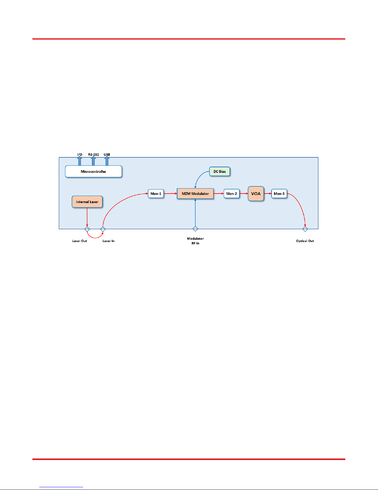
Each E-O converter is fully integrated and contains the laser source, lithium niobate (LiNbO3) Mach-Zehnder intensity modulator
(MZM), and automatic bias controller; the only required external input is the signal source to the Modulator RF In port.
The MX40G/MX70G, MX40G-LB/MX70G-LB, and MX40G-1310/MX70G-1310 include a C-band tunable laser, an L-band
tunable laser, and a 1310 nm fixed-wavelength laser, respectively. Both the C- and L-band laser sources are tunable on the ITU
50 GHz grid and include a dither feature for wavelength stabilization. An external laser source, operating from 1250 nm to
1610 nm, can also be used to provide the optical input.
Either the internal laser or an external laser source may be coupled to the Laser In port, which uses PM fiber with light linearly
polarized along the slow axis, as shown on the front panel. The maximum input power to the Laser In port is 20 dBm (100 mW).
Optical power is monitored in three places (Mon-1,-2,-3) for the purpose of enabling bias and power control. These power values
are also available at the I/O port. Mon-1 is at the Laser Input, Mon-2 is at the MZM Output, and Mon-3 is at the final Optical
Output.
Figure 1 Key Components of the E-O Converter
Page 2 TTN116413-D02
Page 7
MX40G, MX70G Series of E-O Converters Chapter 1: Introduction
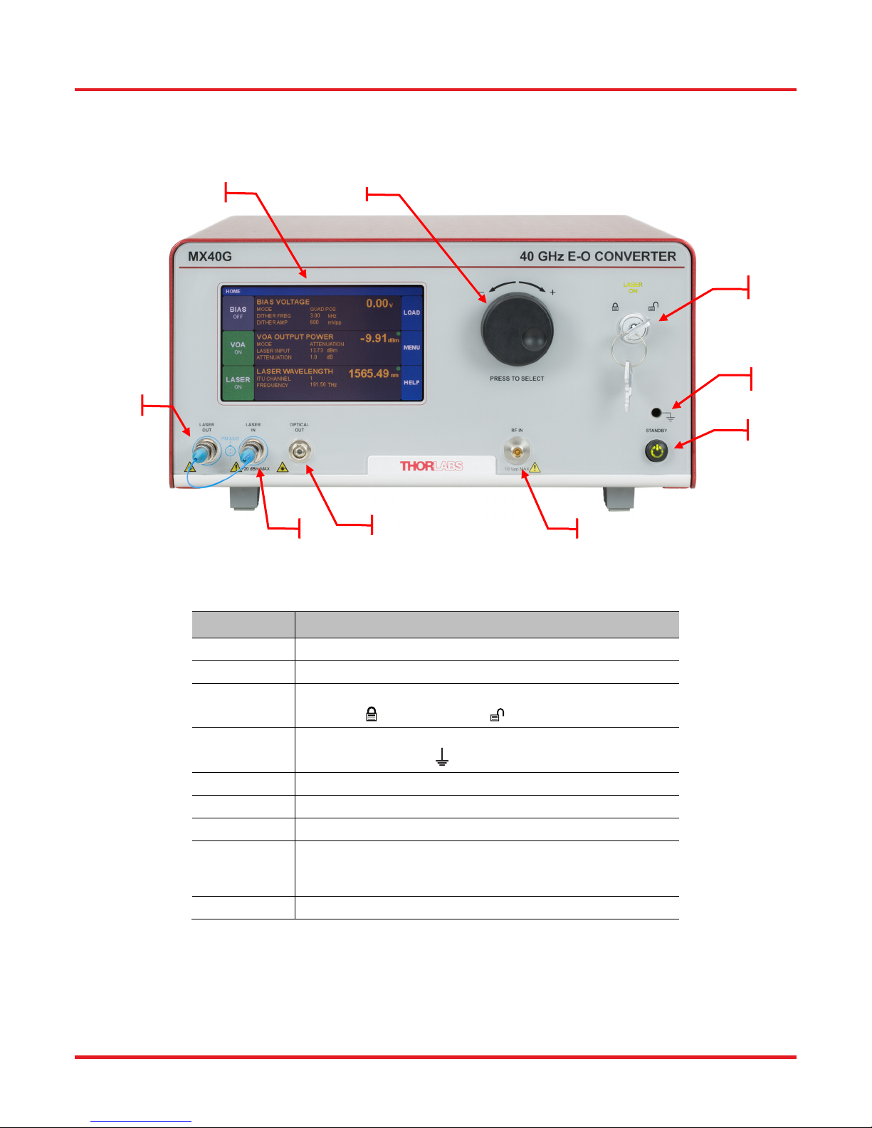
1.4 Front and Back Panel Overview
F1
F5
F2
F3
F4
F9
Callout Description
F1
F2
F3
F4
F5
F6
F7
F8
F9
F6
F7
F8
Figure 2 Front Panel
Touchscreen Display
Adjustment Knob
Key Switch and Status Indicator
Lasing Disabled; Lasing Enabled
Grounding Jack (Banana Connector)
Earth Ground
Laser Output (PM FC/PC Connector)
Laser Input (PM FC/PC Connector)
Optical Output (FC/PC Connector)
Modulator RF Input
(MX40G Series: 2.92 mm Connector;
MX70G Series: 1.85 mm Connector)
Standby Button
Rev. E, March 19, 2019 Page 3
Page 8
MX40G, MX70G Series of E-O Converters Chapter 1: Introduction
B1
B2
B6
B3
B4
B7
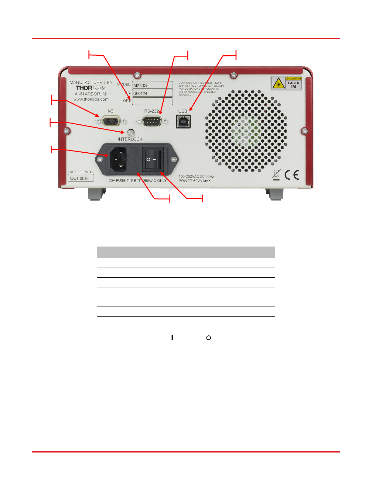
Figure 3 Back Panel
B8
B5
Callout Description
B1
B2
B3
B4
B5
B6
B7
B8
I/O Port (DB15 Connector)
Laser Interlock (2.5 mm Connector)
Option Label
RS-232 Port (DB9 Connector)
USB Port (USB Type B Connector)
Power Connector
Fuse Tray
Power Switch
Supply On; Supply Off
Page 4 TTN116413-D02
Page 9
MX40G, MX70G Series of E-O Converters Chapter 2: Safety
Chapter 2 Safety
All statements regarding safety of operation and technical data in this instruction manual will only apply when the unit is operated
correctly. If equipment is used in a manner not specified by the manufacturer, the protection provided by the equipment may be
impaired. Only with written consent from Thorlabs may changes to single components be carried out or components not supplied
by Thorlabs be used.
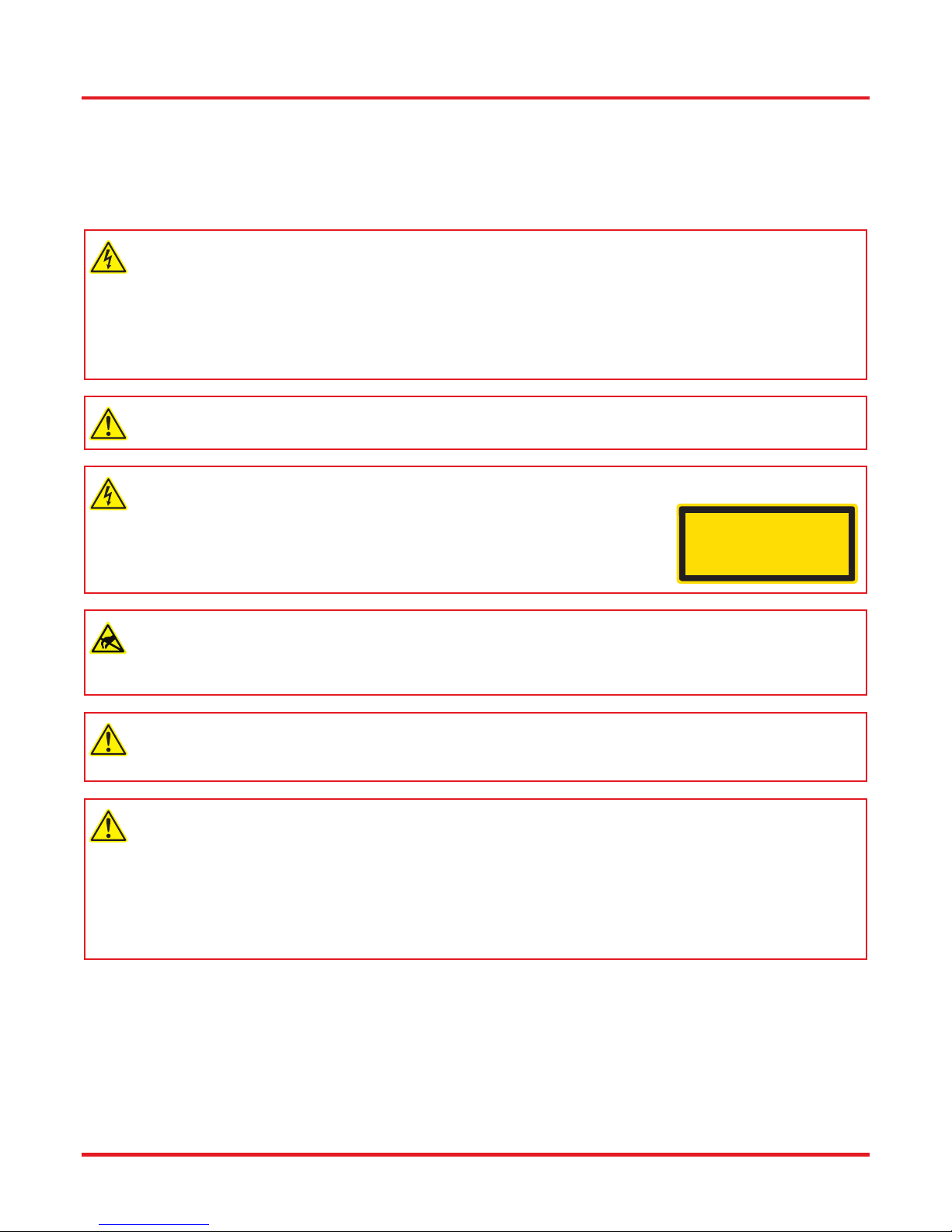
Warning: Risk of Electrical Shock
Before applying power to the instrument, make sure that the protective conductor of the 3 conductor mains power
cord is correctly connected to the protective earth contact of the socket outlet. Improper grounding can cause electric
shock with damage to your health or even death. Only use mains cable with sufficient current and voltage ratings for
this instrument. The local supply voltage must be in the range specified on the rear panel, and the correct fuse must
be installed in the fuse holder. If not, please replace the main fuse (see Section 8.3). Do not position equipment in a
way that makes it difficult for the user to operate the disconnecting device. Do not remove covers. Refer servicing to
qualified personnel.
Warning: Risk of Explosion
The instrument must not be operated in explosion endangered environments.
Warning: Laser Radiation
Avoid Exposure – Radiation emitted from apertures. Do not look into the laser
aperture while the laser is on. Injury to the eye may result. Laser should not be turned
on unless there is an optical fiber connected to the laser output port.
Caution – Use of controls or adjustments or performance of procedures other than
those specified herein may result in hazardous radiation exposure.
LASER RADIATION
DO NOT VIEW DIRECTLY WITH
OPTICAL INSTRUMENTS
CLASS 1M LASER PRODUCT
Caution: ESD Sensitive Component
The components inside this instrument are ESD sensitive. Take all appropriate precautions to discharge personnel
and equipment before making any connections to the unit. A front panel grounding jack is provided for connection to
a wrist strap.
Caution: Components not Water Resistant
This instrument should be kept clear of environments where liquid spills or condensing moisture are likely. It is not
water resistant. To avoid damage to the instrument, do not expose it to spray, liquids, or solvents.
Caution: Follow Intended Usage Guidelines
This product is not suitable for household room illumination.
Inputs and outputs must only be connected with shielded connection cables.
Do not obstruct the air ventilation slots in housing.
Mobile telephones, cellular phones or other radio transmitters are not to be used within the range of three meters of
this unit since the electromagnetic field intensity may then exceed the maximum allowed disturbance values according
to IEC 61326-1.
Rev. E, March 19, 2019 Page 5
Page 10

MX40G, MX70G Series of E-O Converters Chapter 2: Safety
The following statement applies to the products covered in this manual, unless otherwise specified herein. The statement for
other products will appear in the accompanying documentation.
Note: This equipment has been tested and found to comply with the limits for a Class B digital device, pursuant to Part 15 of the
FCC Rules and meets all requirements of the Canadian Interference Causing Equipment Standard ICES-003 for digital
apparatus. These limits are designed to provide reasonable protection against harmful interference in a residential installation.
This equipment generates, uses, and can radiate radio frequency energy and, if not installed and used in accordance with the
instructions, may cause harmful interference to radio communications. However, there is no guarantee that interference will not
occur in a particular installation.
This product has been tested and found to comply with the limits according to IEC 61326-1 for using connection cables shorter
than 3 meters (9.8 feet).
Thorlabs is not responsible for any radio television interference caused by modifications of this equipment or the substitution or
attachment of connecting cables and equipment other than those specified by Thorlabs. The correction of interference caused
by such unauthorized modification, substitution or attachment will be the responsibility of the user. The use of shielded I/O cables
is required when connecting this equipment to any and all optional peripheral or host devices. Failure to do so may violate FCC
and ICES rules.
This precision device should only be shipped if packed into the complete original packaging including the custom cut foam
padding. If necessary, ask for replacement packing material.
Page 6 TTN116413-D02
Page 11
MX40G, MX70G Series of E-O Converters Chapter 3: Quick Start Guide
Chapter 3 Quick Start Guide
3.1 Hardware Set Up
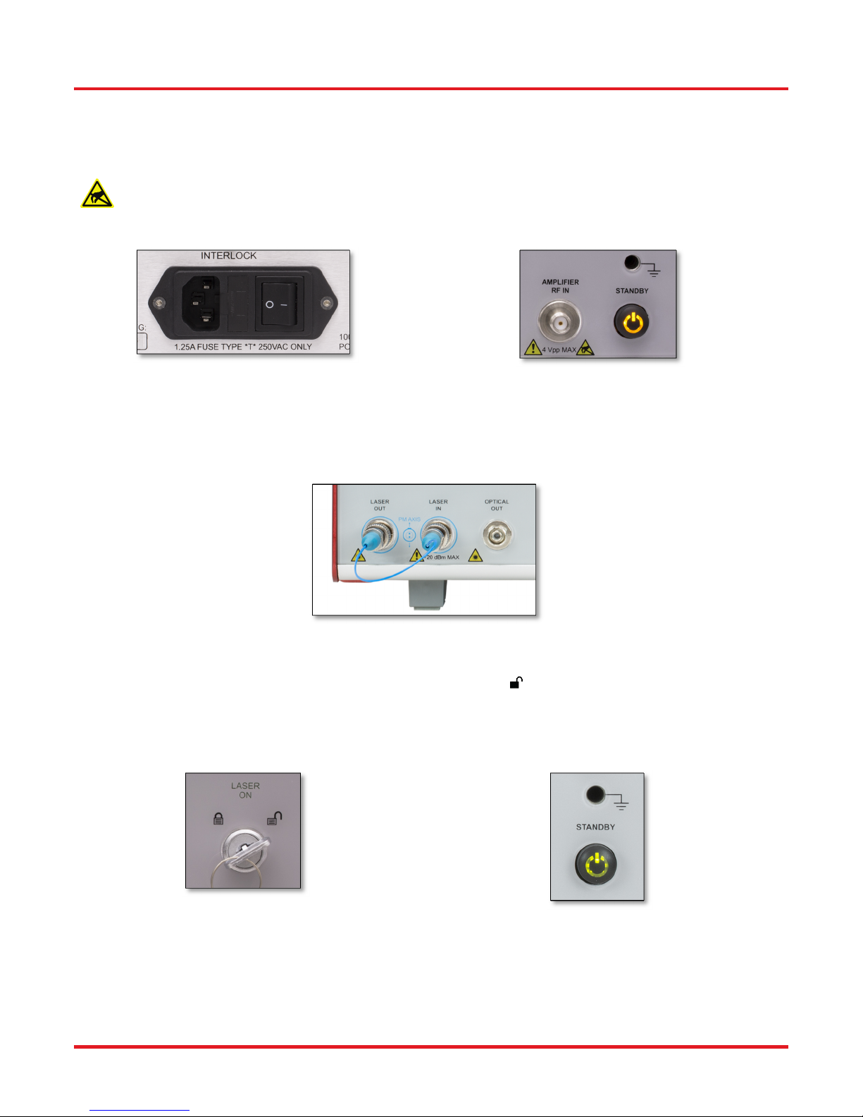
For first use, plug the main power cable into the rear panel connector, and then plug the other end into an AC wall
receptacle. Flip the power switch on the rear panel to the ON (I) position. The unit will now be in the “Standby” mode,
and the front panel standby button should glow amber.
Figure 4 Power Cable Port, Fuse, and Power
Switch
Attach the PM loop-back fiber optic cable between the Laser Out and Laser In FC connectors on the front panel. Be sure to
clean both ends of the fiber as described in the Maintenance Section of this manual.
Figure 6 PM Loopback Fiber Cable Installed
Insert the key into the interlock switch and turn it towards the unlock symbol ( ). This allows the laser to be turned on, but the
LASER ON indicator will not glow green until the laser is actually turned on by the touchscreen button. Turn on the unit by
pressing the amber standby button on the front panel which will then turn green to indicate the unit is fully on. The touchscreen
display will come up with a boot screen for about 5 seconds and then go to the home page. The unit will initialize in the factory
default state with all functions OFF.
Figure 5 Indicator Glows Amber when Converter is
In Standby
Figure 7 Interlock Key Switch
Rev. E, March 19, 2019 Page 7
Figure 8 Indicator Glows Green when Converter is
Fully Enabled
Page 12
MX40G, MX70G Series of E-O Converters Chapter 3: Quick Start Guide
3.2 Controls on the Home Page
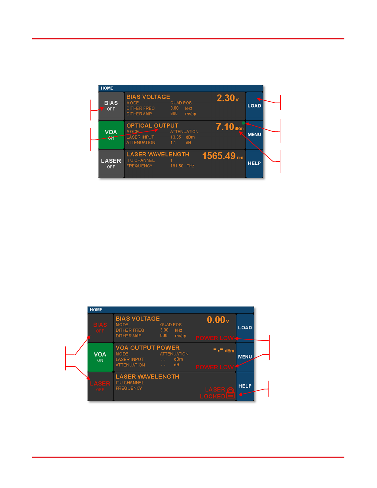
Full access to all of the converter's controls and functions is available using the resistive touchscreen display, which is sensitive
to finger pressure or the tap of a plastic stylus. In addition, the knob on the front panel can be used in place of the on-screen
arrow buttons for quickly changing set-point values. Pressing (clicking) the knob will confirm a new set-point value.
Tap these buttons
to turn functions
ON or OFF.
Tap in these areas
to go to the related
Settings pages.
Figure 9 Home Screen Features
The Home screen (or dashboard) is organized into three main sections.
The left side contains the ON/OFF buttons for each of the main instrument functions. Tapping any of these buttons will toggle
the function on and off. The same ON/OFF functionality is also available on the individual Settings pages. The power buttons
turn green to indicate the function is ON, and they turn red to indicate the function is disabled.
The central section is the main dashboard for reporting operational values of each section. Tapping the screen in this middle
area will take the user to the corresponding Settings page for each section. Note that the green dot in each of these sections
glows steadily to indicate the function is stable, and it blinks to indicate the function is still stabilizing.
The right side of the screen provides access to the main utility functions of the box.
Blue Button:
Utility Functions
Green dot flashes or is
steady to indicate
stability state.
Power units (dBm or
mW) are set in the
VOA Settings page.
The screen shot below shows some of the common warning indicators on the Home page. Some functions can be disabled
when the laser power is low. In this case, buttons may be disabled and warnings indicators may appear.
Low Power
Disabled
Functions
Figure 10 Home Screen Warnings and Indicators
Warnings
Interlock
Warning
Page 8 TTN116413-D02
Page 13
MX40G, MX70G Series of E-O Converters Chapter 3: Quick Start Guide
3.3 System Wavelength Setting
The operational wavelength range of each converter extends from 1250 nm to 1610 nm. The three calibration wavelengths of
the power monitors, 1310 nm, 1550 nm, and 1590 nm, represent the centers of the O-band, C-band, and L-band and provide
the user with accurate power readings at or near those wavelengths.
The system wavelength should always be set to the wavelength closest to that of the laser source coupled to the Laser In
bulkhead. The converter's system wavelength is factory-preset to correspond to the wavelength band of the integrated laser
source. If an external laser is to be used with the converter, the system wavelength may need to be changed. This function exists
in the Utility Menu.
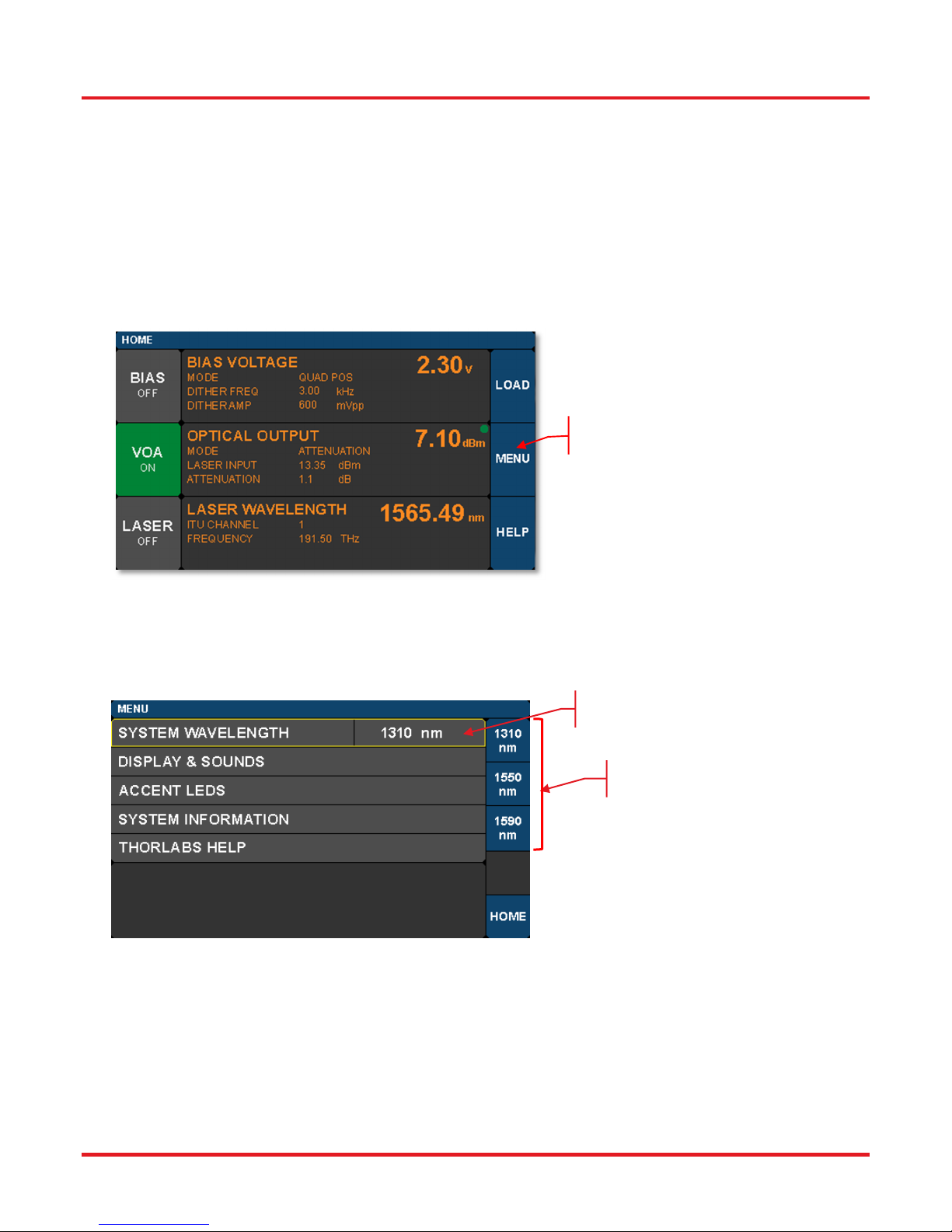
From the Home screen, tap the MENU button to bring up the Utility Menu as shown.
Tap the MENU button to
access the Utility Menu.
Figure 11 Accessing the Utility Menu from the Home Screen
Then tap the System Wavelength bar as shown below to bring up the three wavelength choices. Tap the desired wavelength to
set the System Wavelength.
Tap here to activate
wavelength selection.
Choose one of these
wavelengths.
Figure 12 System Wavelength is Selected from the Utility Menu
Rev. E, March 19, 2019 Page 9
Page 14
MX40G, MX70G Series of E-O Converters Chapter 3: Quick Start Guide
3.4 Controls on the Settings Pages
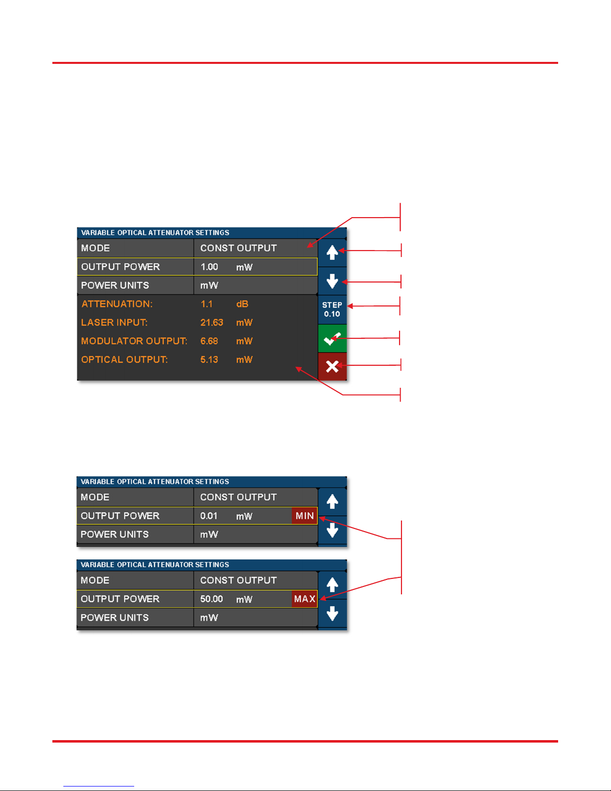
The Settings pages all possess the same general design and functionality as shown in the example screen shot below. The
upper section with white letters displays the parameters that can be changed. Simply tap on the parameter of interest. A yellow
border highlights the choice and controls for that parameter are presented.
The lower section with amber letters displays selected related values convenient to monitor from the page.
The right-hand column provides the controls for changing the values for the selected parameters. The main control knob on the
front panel can also be used to adjust and confirm selected values. The screen shots below show examples of the touch-screen
controls.
Tap parameter to select it.
Yellow border highlights choice.
Increase value by tapping.
Decrease value by tapping.
Change step size by tapping.
Confirm new value by tapping.
Cancel any changes by tapping.
Monitor Area
Figure 13 Controls used to Adjust and Save Values of Selected Parameters
Fields that have adjustable values will show a flag if the minimum or maximum values have been reached. These are set by
firmware at the factory.
MIN / MAX warnings
indicate that the setting
limit for a particular
parameter has been
reached.
Figure 14 MIN and MAX Flags Indicate Bounds of Adjustable Value Ranges
Page 10 TTN116413-D02
Page 15
MX40G, MX70G Series of E-O Converters Chapter 3: Quick Start Guide
3.5 Quick Start
The following steps summarize the setup procedure required to operate the converter in the standard mode. Please refer to
previous sections in this chapter and the expanded operating instructions in Chapter 4 for additional information.
1. Turn on power to the converter via the power switch on the back panel (Figure 4).
2. Press and hold the button on the front panel until the indicator light changes from amber to green (Figure 5 and Figure 8).
3. Turn the key switch to unlock (Figure 7).
4. Turn the laser on by tapping the lower-left touchscreen button on the Home page (Figure 9).
5. Enable the bias controller by tapping the top-left touchscreen button on the Home page (Figure 9). Wait for completion of
the calibration process. The instrument will enable the default Quadrature mode with positive slope bias point (Section
4.4.1).
6. Take note of the output power, which is shown in the center right section of the Home page (Figure 9).
7. Turn on the VOA controller to adjust output power, if desired, by tapping the center-left touchscreen button on the Home
page (Figure 9).
8. Apply the input RF signal to the female RF IN connector on the front panel (Figure 6); the maximum modulator RF input for
linear response is specified in Chapter 5.
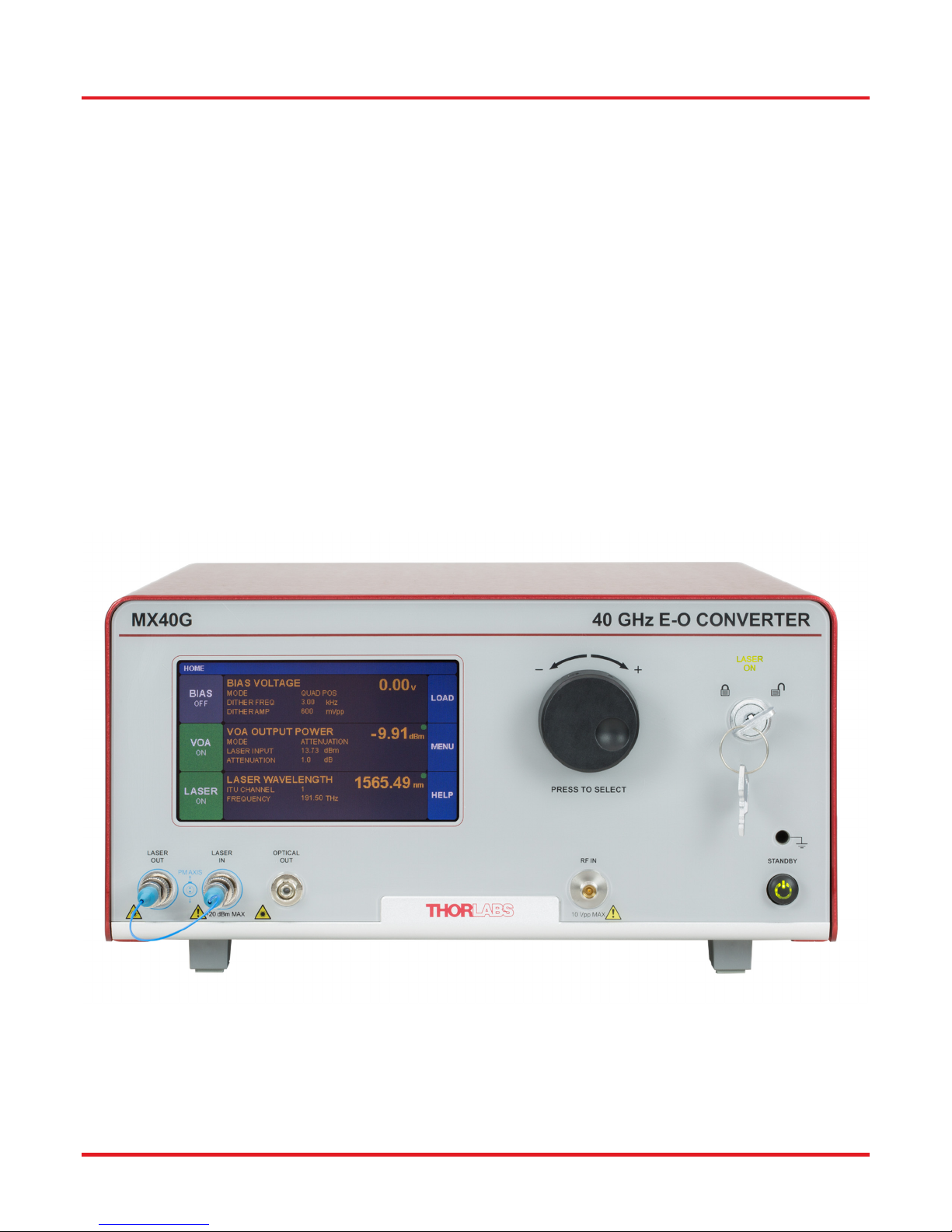
Figure 15 The Front Panel of the MX40G Converter
Rev. E, March 19, 2019 Page 11
Page 16
MX40G, MX70G Series of E-O Converters Chapter 4: Operating Instructions
Chapter 4 Operating Instructions
4.1 The Modulator Transmission Function
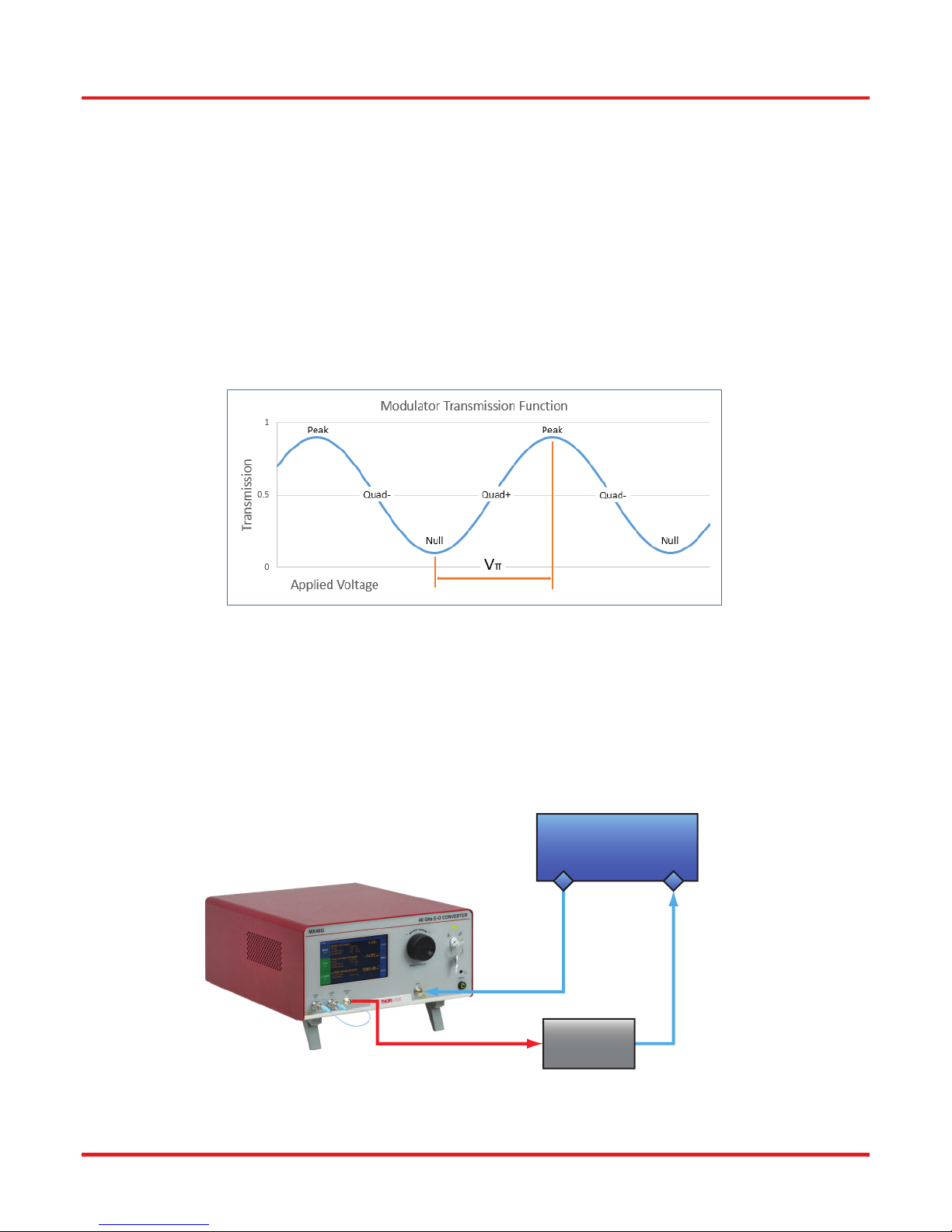
The Mach-Zehnder modulator (MZM) has a repetitive transmission function with applied voltage as can be seen in the diagram
below. In order for the MZM to work correctly, a DC bias voltage must be applied and maintained at the desired set point. The
high-frequency AC signal can then be applied to the modulator to enable the correct optical modulation of the laser beam. The
most common operating points are the peak, null, and quadrature points as shown below.
The purpose of the Bias settings is to hold the modulator at one of these chosen points. Note that a real transmission function
does not go perfectly from 0% to 100%. This is characterized by the Extinction Ratio of the modulator (Peak power / Null power).
The efficiency of the modulator is also characterized by V
from Null to Peak. The most linear response of the modulator is achieved by biasing it at one of the Quadrature points where
the transmission is closest to 50%. Some non-linear, frequency doubling, and phase modulation applications require biasing at
the Null or Peak.
, which is defined as the voltage necessary to change the transmission
π
Figure 16 Illustration of the Modulator Transmission Function
4.2 De-Embedding Procedures
One of the primary applications of a calibrated electrical to optical (E-O) converter is enabling electrical to electrical (E-E) test
equipment, like a VNA, to characterize optical to electrical (O-E) devices. As illustrated in Figure 17, the device converts the
electrical signal from Port 1 of the E-E VNA to an optical signal that is input into the O-E DUT, and the electrical signal resulting
from the O-E DUT is then provided to Port 2 of the E-E test equipment. The response of the entire E-E system, which consists
of the converter and the O-E DUT together, is measured. Accurately recovering the response of the O-E DUT requires removing
the response of the converter from the measured E-E system response. This is referred to as de-embedding.
Electrical Vector
Network Analyzer
Port 2Port 1
Electrical
Electrical
O-E Device
MX40G E-O Converter
Optical
Under Test
Figure 17 An E-O Converter Provides Optical Test Capability for an All-Electrical VNA
Page 12 TTN116413-D02
Page 17
MX40G, MX70G Series of E-O Converters Chapter 4: Operating Instructions
Thorlabs provides a file (.s2p format) with each E-O converter that contains the S21 magnitude and phase response of the
modulator across its frequency range of operation. These data are used to perform the de-embedding process. Note that most
modern E-E VNA systems provide a built in function for doing this type of de-embedding based on the user-supplied .s2p file.
This is the easiest method. However, the de-embedding process can also be performed manually. These methods are
described in detail in the "De-Embed Application Note" PDF document, which is accessible by visiting
www.thorlabs.com/manuals and entering the item # of your E-O Converter.
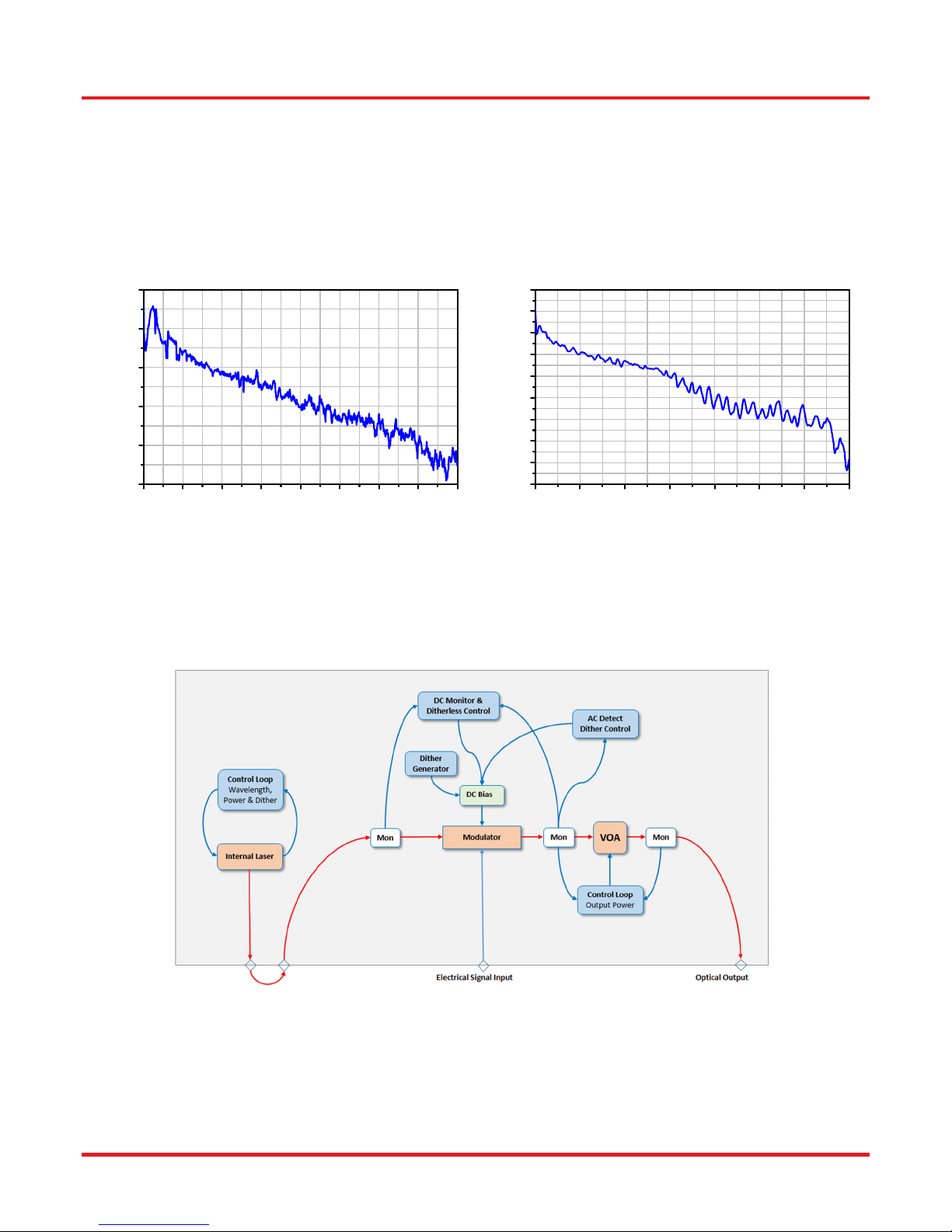
A typical frequency response for each converter is plotted below in Figure 18. The phase response is not shown.
MX40G Typical Frequency Response
1
0
-1
-2
Power (dB)
-3
-4
0 5 10 15 20 25 30 35 40
Frequency (GHz)
MX70G Typical Frequency Response
2
1
0
-1
-2
-3
-4
Power (dB)
-5
-6
-7
0 10203040506070
Frequency (GHz)
Figure 18 Typical Frequency Response of the MX40G Series and MX70G Series
4.3 Control Loop Diagram
The following diagram shows the control loops added to the block diagram. From this picture, the user can see how the power
monitors and VOA are used to provide stability and control to the whole system. It will be helpful to refer to this diagram to gain
a better understanding of the functionality of the unit as described in the upcoming sections of the manual.
Figure 19 Block Diagram of the Converter Showing Control Loops
Rev. E, March 19, 2019 Page 13
Page 18
MX40G, MX70G Series of E-O Converters Chapter 4: Operating Instructions
4.4 Bias Settings Page
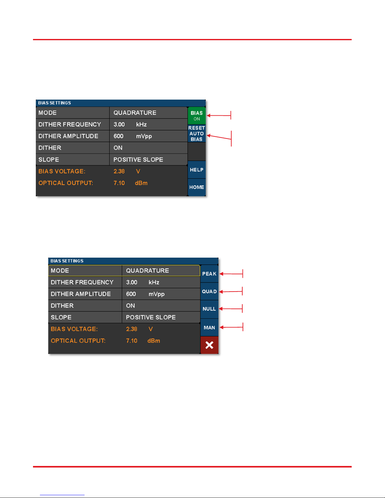
The Bias Settings page is accessed by tapping the center bias monitors pane on the Home page. When the MZM Bias control
is first turned on, the converter performs a calibration routine to determine the approximate bias voltages required for the various
MZM operating points. This allows the instrument to quickly and effectively switch between bias modes. The user may perform
this calibration anytime by pressing the Reset Auto Bias button on the right side of the Bias Settings page. This button is not
available if the Bias is off or in Manual mode.
Tap to turn Bias On/Off.
Tap to Reset Modulator Bias.
New set points will be stored.
Figure 20 Bias Settings Home Screen
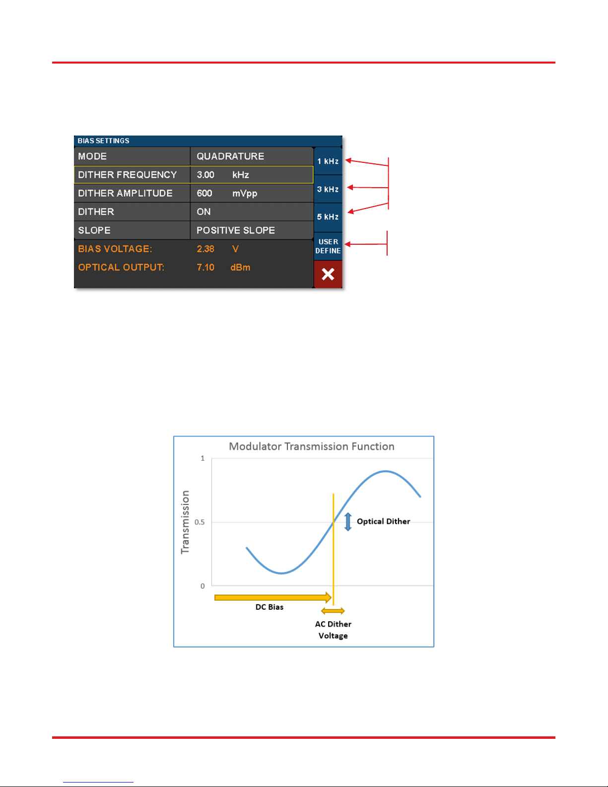
The Bias Settings page contains the settings for controlling the modulator bias and operating modes. There are four modes for
MZM bias control: 1) Quadrature, 2) Peak, 3) Null, and 4) Manual. The screen shot below is an example of the information
presented and the controls available when the Mode field is selected while the controller is operating in Quadrature mode. The
blue buttons enable switching between modes.
Tap to select Peak Mode.
Tap to select Quadrature Mode.
Tap to select Null Mode.
Tap to select Manual Mode.
Figure 21 Bias Settings Screen when Mode Field is Selected while Quadrature Mode is Enabled
Active control of the MZM bias point is essential, as the modulator is temperature sensitive and will drift over time. The
Quadrature, Peak, and Null modes use a dither tone as part of a lock-in control scheme to keep the MZM bias stable. The dither
tone allows the control algorithm to track the drifting, but at the cost of decreased signal-to-noise ratio (SNR) due to the injection
of a single frequency tone into the MZM bias.
Page 14 TTN116413-D02
Page 19
MX40G, MX70G Series of E-O Converters Chapter 4: Operating Instructions
A
4.4.1 Quadrature Mode
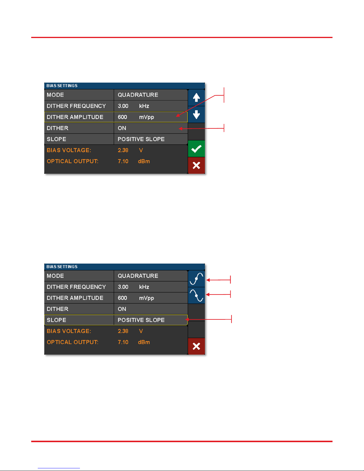
Quadrature mode is the default mode and biases the MZM at the 50% point on the MZM transmission curve shown in Figure
23. Quadrature mode is essential for VNA applications in which linear response is critical. The screen shot below shows the
parameters that can be controlled in the Quadrature mode.
One option: choose one of three
preset dither frequencies.
nother option: specify custom dither
frequency between 1 and 10 kHz.
Figure 22 Dither Frequency Selection while Quadrature Mode Enabled
The bias control circuit uses an AC dither tone to stabilize the bias point of the modulator, as illustrated below. A small AC
voltage is applied to the DC bias so that the optical output is also slightly modulated. Both the amplitude and the frequency of
AC dither tone can be selected by the user. The modulated optical output is detected by a frequency and phase sensitive
detector, which can then interpret whether the DC bias is at the correct level for the chosen set-point (Quadrature, Peak or Null).
The DC bias voltage is then continuously adjusted to maintain the correct set-point.
The frequency of the dither tone will not exceed 10 kHz. This frequency limit, which is usually well below the low frequency cutoff for the RF signal of interest, is chosen to prevent interference. As described in the following, the dither tone can also be
turned if other methods of bias control are desired (e.g. manual or input/output ratio control).
Figure 23 AC dither tone stabilizes the bias point of the modulator.
Rev. E, March 19, 2019 Page 15
Page 20
MX40G, MX70G Series of E-O Converters Chapter 4: Operating Instructions
A
The dither tone frequency may be changed by tapping the Dither Frequency field, which is highlighted in Figure 22. Standard
frequencies are selected using the blue buttons, or a custom frequency may be chosen by pressing User Define. The dither
tone frequency usually has very little effect on the accuracy of the bias control, but in some cases a different frequency may
work better or be desirable depending on the RF signal applied or on the specific application. The User Define button allows
for the selection of an arbitrary frequency between 1 kHz and 10 kHz with 10 Hz resolution.
djust the dither amplitude by
selecting this field.
Tap here to turn dither On/Off.
Figure 24 Dither Amplitude Adjustment
The dither tone amplitude can also be adjusted to any amplitude between 20 mV and 2 V with 1 mV resolution by tapping the
Dither Amplitude field highlighted in Figure 24. Higher amplitudes will typically be more stable in the presence of MZM drift and
broadband RF signals, but larger dither tones also decrease SNR. If the amplitude is too low, the MZM bias may not stay
locked. Typically, a value from 300 mV to 500 mV is a good starting point.
The dither tone can be optionally disabled to accommodate applications requiring the highest SNR. The user may quickly turn
the dither off, perform a measurement requiring low noise, and then turn the dither back on. When the dither is turned off, the
bias is simply held at the previous bias voltage. Manual Mode should be used for longer-term measurements without dither, so
that a constant ratio method can be used to stabilize the bias point, as described in Section 4.4.4.
Tap to select positive slope.
Tap to select negative slope.
Tap to change slope selection.
Figure 25 Choose the Positive or Negative Slope of the Transmission Function
Quadrature mode also allows the user to select between two operating points by selecting the Slope field. Positive slope is the
non-inverting operating point where increasing voltage on the MZM results in increasing optical output power. Negative slope is
the inverting operating point where increasing voltage on the MZM results in decreasing optical output power. This effectively
changes the phase of the response function.
Page 16 TTN116413-D02
Page 21
MX40G, MX70G Series of E-O Converters Chapter 4: Operating Instructions
4.4.2 Peak Mode
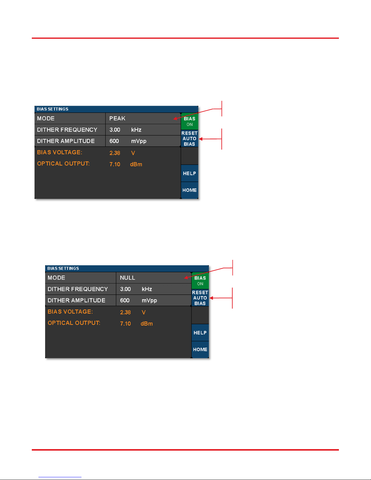
The Peak Mode adjusts the DC bias voltage so the transmission is centered at a nearby transmission maximum. In this mode
only dither frequency and amplitude settings are available. These controls and settings are the same as previously described
for the Quadrature mode.
Peak and Null modes are often used to obtain phase modulation and non-linear frequency doubling. The optical phase is 180°
shifted on opposite sides of the Null point.
Peak mode is active, tap this
field to change.
Tap here to reset the Bias
calibration and return to
Peak mode.
Figure 26 Peak Mode Settings
4.4.3
The Null Mode adjusts the DC bias voltage so the transmission is centered at a nearby transmission minimum. In the Null
mode only dither frequency and amplitude settings are available. These settings are the same as previously described for the
Quadrature mode
Null Mode
Null mode is active, tap this field
to change.
Tap here to reset the Bias
calibration and return to Null
mode.
Figure 27 Null Mode Settings
Rev. E, March 19, 2019 Page 17
Page 22
MX40G, MX70G Series of E-O Converters Chapter 4: Operating Instructions
4.4.4 Manual Mode
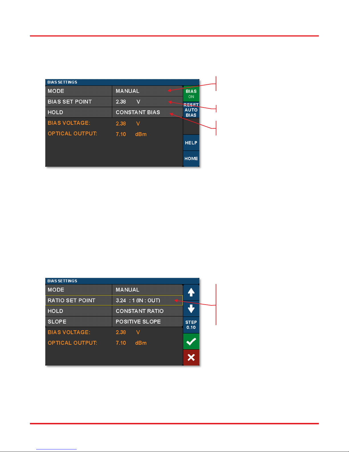
The Manual mode allows the user to bias the modulator at any desired point of the transmission function. Manual mode offers
two operation options: 1) Constant Bias, or 2) Constant Ratio. In both of these options, the dither function is not active, and the
controller uses different techniques to hold the bias steady. The desired option is chosen by selecting the HOLD field.
Manual mode is active, tap this field
to change.
Tap here to adjust Bias voltage.
Tap here to select: between Constant
Bias or Constant Ratio options.
Figure 28 Constant Bias Manual Mode Settings
Constant Bias is the most basic mode of operation and will apply a user selected DC voltage to the MZM. This can be useful for
performing brief measurements that only take a few minutes. During longer duration experiments, the MZM is more likely to drift.
The Constant Ratio mode employs active control of the MZM bias, but without using a dither tone. As a result, it can achieve
superior SNR compared to the Quadrature mode. This mode is recommended for analog signals or higher level Pulse-Amplitude
Modulation (PAM) formats.
Constant Ratio works by holding the MZM ratio of input light (at Mon-1) to output light (at Mon-2), see Figure 1 for reference, at
a constant value (typically at or close to Quadrature). Note that Constant Ratio does NOT take into account the insertion loss
(IL) of the MZM. Therefore, the user must have some knowledge of the IL between Mon-1 and Mon-2, which is equivalent to the
IL of the modulator. For example. If the modulator has an IL of 3 dB, then the I/O ratio at maximum transmission is already 2:1.
To bias the modulator at the 50% point, the ratio must be doubled to 4:1. The MZM insertion loss is listed in the specifications.
Tap here to manually adjust the
modulator transmission ratio in
Constant Ratio mode.
This is the ratio of modulator input
power to output power.
Figure 29 Constant Ratio Manual Modes Settings
Page 18 TTN116413-D02
Page 23
MX40G, MX70G Series of E-O Converters Chapter 4: Operating Instructions
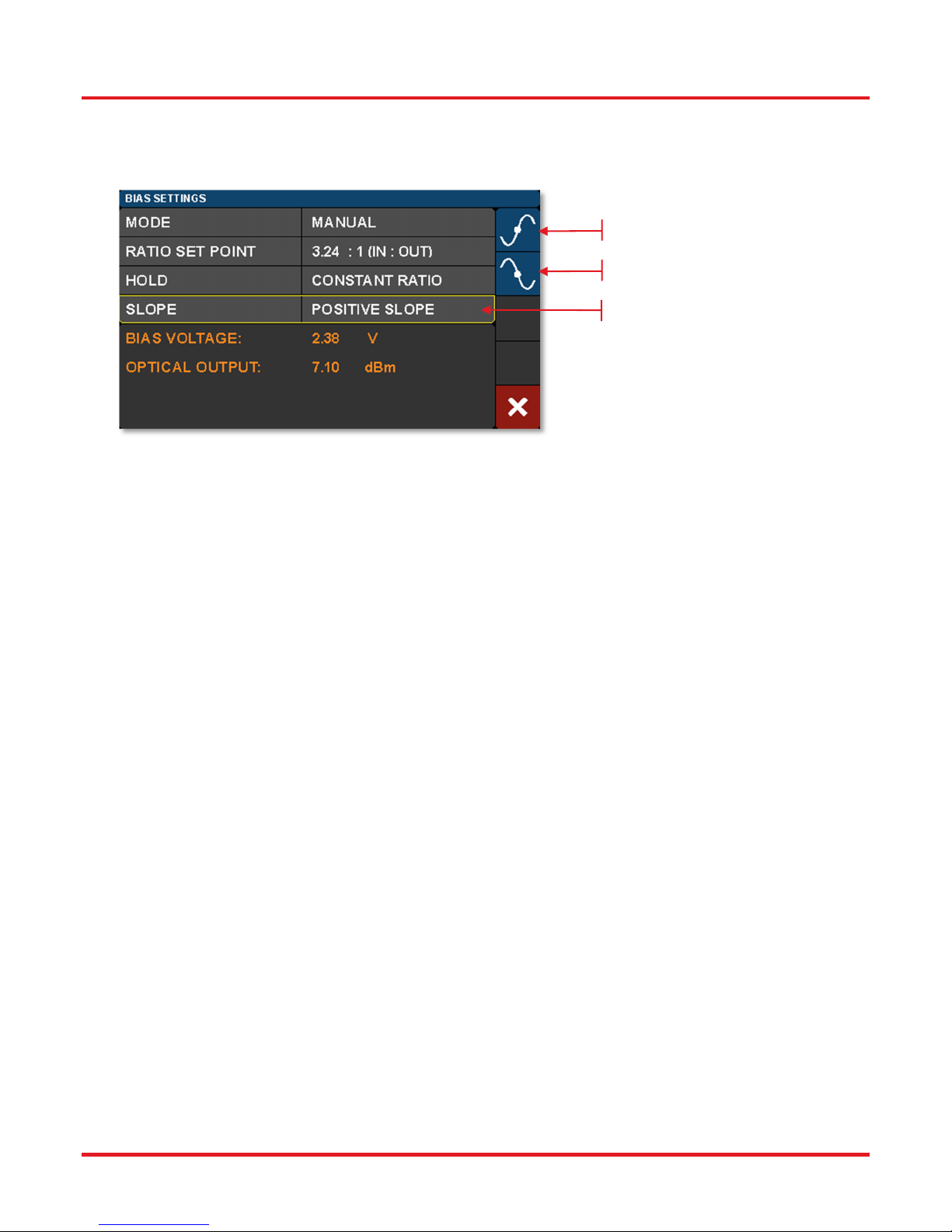
In the Constant Ratio mode there is an option to select between the two available operating regions by selecting the Slope
field. Positive slope is the non-inverting operating point where increasing voltage on the MZM results in increasing optical
output power. Negative slope is the inverting operating point where increasing voltage on the MZM results in decreasing
optical output power.
Select Positive Slope
Select Negative Slope
Tap here to Change Slope.
Figure 30 Selecting Operating Point in Constant Ratio Mode
When switching to one of the Manual modes from a different bias mode, the Manual mode set point is automatically calculated
to keep the MZM at the same location on the transmission function. For example, in order to switch to Constant Ratio mode at
the Quadrature location, follow these steps:
Turn the bias on, and choose Quadrature mode.
Wait for the green indicator dot to stop blinking (indicating the bias is locked at quadrature).
Optional: For greater accuracy at this point, slowly reduce the dither tone amplitude to ~100 mV in order to remove
errors that can occur due to second order effects with a large dither tone. Make sure the green dot is not blinking.
Now change the bias mode to Manual and select Constant Ratio.
The instrument will calculate the ratio to keep the MZM biased at the Quadrature location.
From here, the ratio set point can be adjusted to further tune performance.
Rev. E, March 19, 2019 Page 19
Page 24
MX40G, MX70G Series of E-O Converters Chapter 4: Operating Instructions
A
A
4.5 Variable Optical Attenuator Settings Page
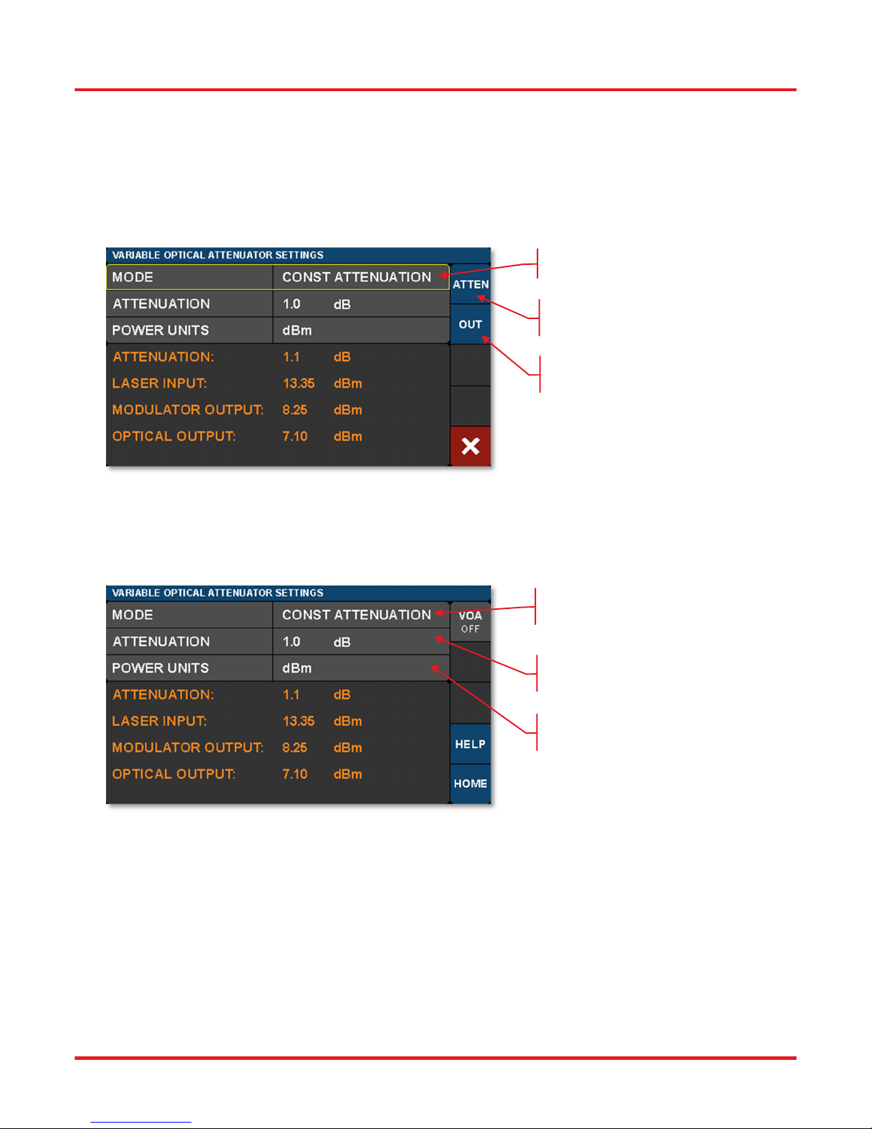
Tap in the VOA monitors pane on the Home page to access the Variable Optical Attenuator (VOA) Settings page shown
below. The VOA provides the means for adjusting and stabilizing the output power after the MZM.
Note that units of all power measurements are determined by the Power Units setting this page, see Figure 32.
The VOA can operate in either of two modes: 1) Constant Attenuation, and 2) Constant Output Power.
Tap here to change the VOA mode.
Tap here to select Constant
ttenuation mode.
Tap here to select Constant
Output Power mode.
Figure 31 Select between Constant Attenuation and Constant Output Power VOA Modes
Constant Attenuation Mode maintains a fixed attenuation level between the output of the MZM and the output port on the front
panel. Any fluctuations at the input are transferred to the output.
VOA Mode Set to Constant
ttenuation
Tap here to change attenuation
level.
Tap here to change units of all
displayed power measurements.
Figure 32 Constant Attenuation VOA Mode Page Options
Page 20 TTN116413-D02
Page 25
MX40G, MX70G Series of E-O Converters Chapter 4: Operating Instructions
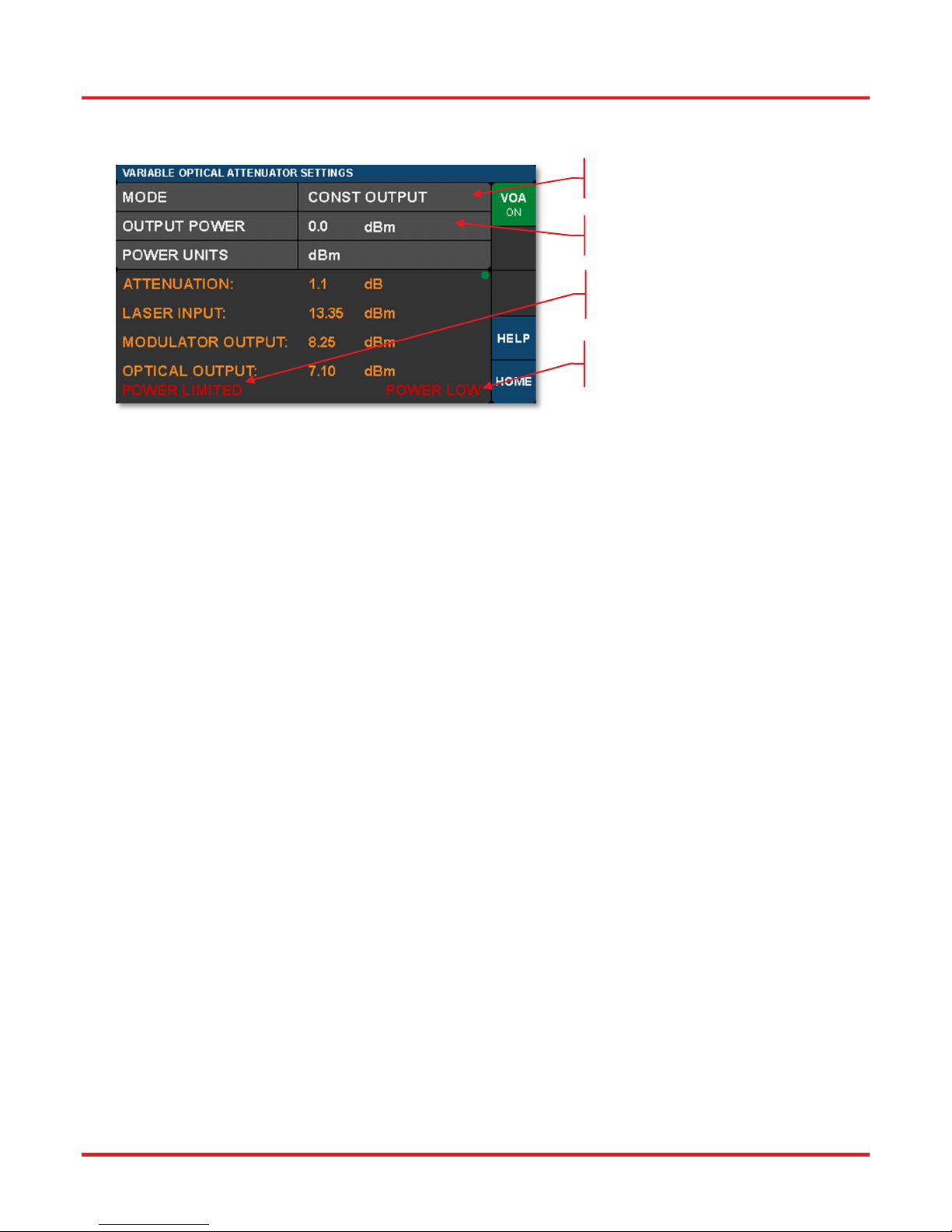
Constant Output Power Mode acts as a stabilizer by holding the final optical power constant independent of input fluctuations
(within controllable limits such as input power and attenuation).
VOA Mode set to Constant
Output Power.
Tap here to adjust output
power.
Warning indicates power is too
low to reach the set point.
Warning indicates loss of VOA
calibration due to low power.
Figure 33 Constant Output Power VOA Mode Page Functions and Possible Warnings
Rev. E, March 19, 2019 Page 21
Page 26
MX40G, MX70G Series of E-O Converters Chapter 4: Operating Instructions
A
4.6 Laser Settings Page
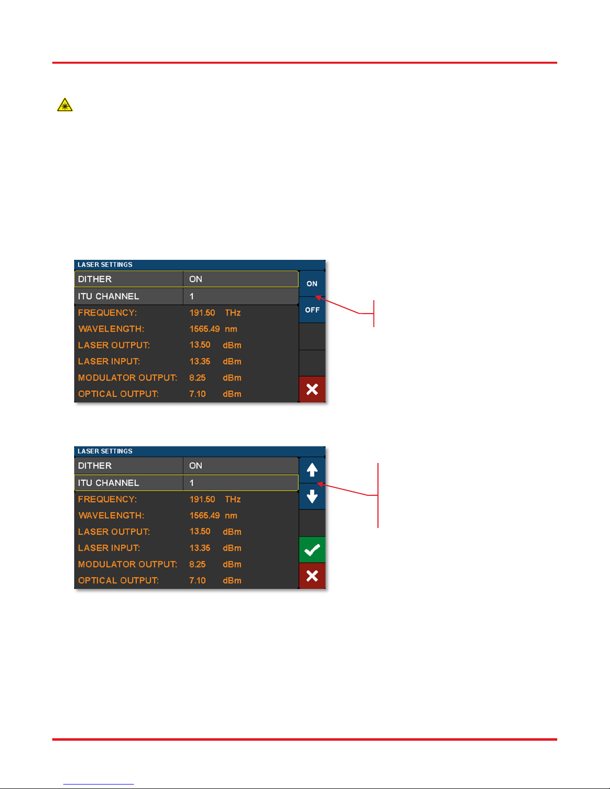
To access the Laser Settings page, tap on the Laser monitors pane on the Home page. Here the user can control the
laser wavelength and choose whether or not to use the dither feature to stabilize the wavelength. Turning the dither
off will result in lower phase and intensity noise, but the wavelength may drift slightly over time. The monitors on this
page provide live readings of many parameters.
When the internal laser source is a C-band or L-band tunable laser, tap on the Laser Monitors pane on the home page to access
the Laser Settings page. This page is not available when the 1310 nm fixed-wavelength source is the internal laser. When the
internal laser is not the standard C-band tunable laser, the laser type is denoted in the Options label on the rear panel of the
instrument (please see Figure 3 for location of the Options label).
Optical frequency can be set at increments of 50 GHz for C-band or L-band tunable internal lasers. The ITU channel number on
these pages is an index number given only for convenience, which is unique to this instrument; actual frequencies and spacings
are specified by the ITU standard.
Use these buttons to toggle the
dither function On/Off.
Figure 34 Controls for Enabling/Disabling Dither Function
Tap here to change the laser
wavelength by channel index
number.
ctual frequency and wavelength are
displayed in the monitor section.
Figure 35 Controls for Adjusting Laser Wavelength by Choosing Index Number of ITU Channel
Page 22 TTN116413-D02
Page 27
MX40G, MX70G Series of E-O Converters Chapter 4: Operating Instructions
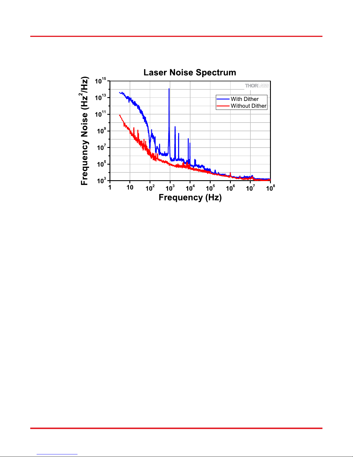
Figure 36 shows laser frequency noise as a function of optical frequency when the laser is operated with and without dither
enabled. The red trace shows low noise operation when dither is turned off. Wavelength stability is improved by operating with
dither, but the blue trace shows that this comes at the expense of added noise.
Figure 36 FM Noise Spectrum of C-Band Laser with and without Dither
Rev. E, March 19, 2019 Page 23
Page 28
MX40G, MX70G Series of E-O Converters Chapter 4: Operating Instructions
4.7 Load Page
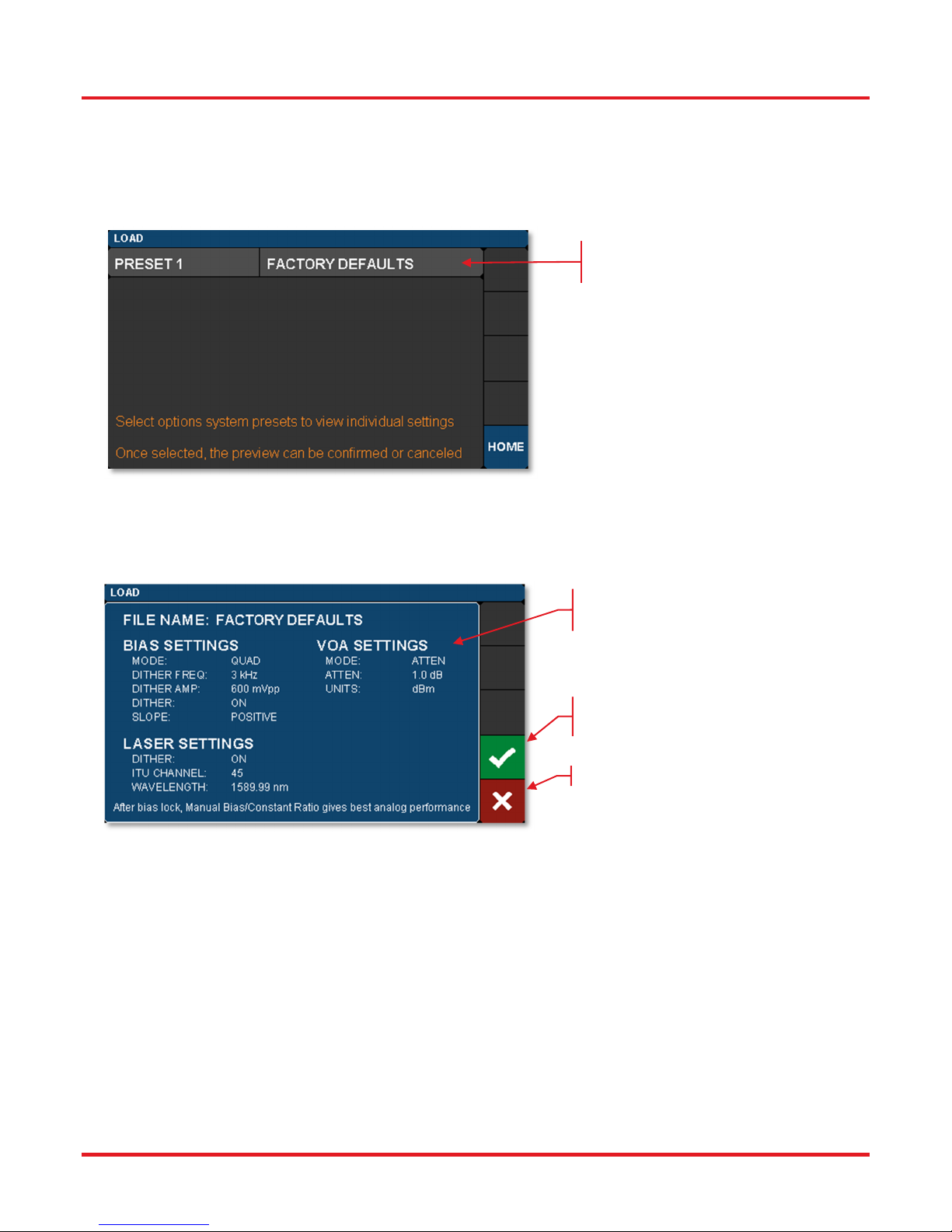
Access the Load page by tapping the blue Load button on the Home page. The Load page has a factory-defined, standard
operating mode stored as a preset. Applying the preset configures the converter with the stored instrument settings and is a fast
way to put the instrument in a known state. Future firmware revisions will have the ability to store instrument states defined by
the user as well.
Tap to preview the settings of the
preset state.
Figure 37 Preset State Option Accessed through the Load Page
Tapping on one of the presets will bring up a window that displays all the stored settings. The user can then review the choice
before confirming with the green check-mark.
This window displays the preset
parameters for review.
Load the preset by tapping the
green check-box.
Cancel by tapping the red button.
Figure 38 Stored Instrument Settings of a Preset
Page 24 TTN116413-D02
Page 29
MX40G, MX70G Series of E-O Converters Chapter 4: Operating Instructions
4.8 Menu Page
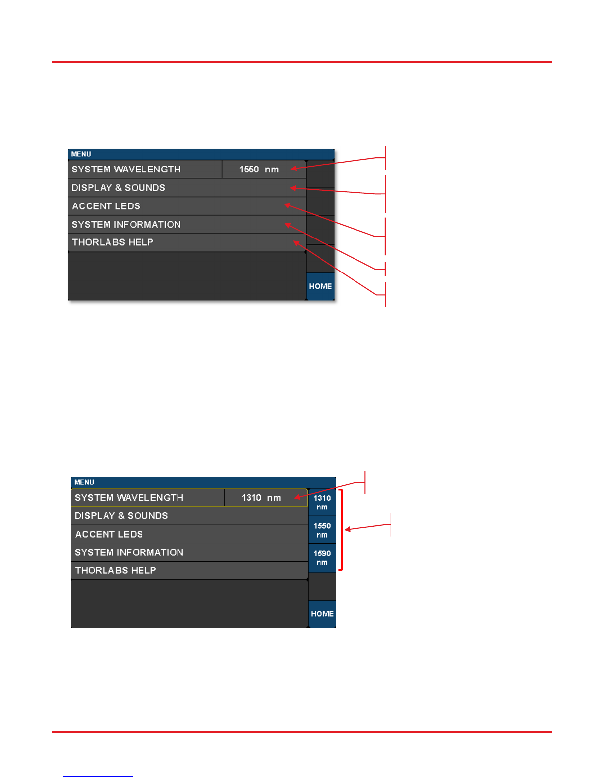
Access the Menu page by tapping the blue Menu button on the Home page. The Menu page links to pages that allow the user
to control the system wavelength, display, sounds, and accent lights. Links to system information and guidance for obtaining
help form Thorlabs’ technical support are also included on this page. The functions and information available through this page
are described in the following sections.
Tap here to set system
wavelength.
Tap here to control the touchscreen
and the sounds made when
interacting with the GUI.
Tap here to control the accent LEDs
producing the light emanating from
the bottom of the instrument.
Tap here to find system information.
Tap here to find help from
Thorlabs Technical Support.
Figure 39 Controls on the Menu Page
4.8.1 System Wavelength
The path to access this screen: Home Page> Menu Page> System Wavelength.
The operational wavelength range of the MX40G and MX70G series of converters extends from 1250 nm to 1610 nm. The three
calibration wavelengths of the power monitors, 1310 nm, 1550 nm, and 1590 nm, represent the centers of the O-band, C-band,
and L-band and provide the user with accurate power readings at or near those wavelengths.
The system wavelength should always be set to the wavelength closest to that of the laser source. Each converter's system
wavelength is factory-preset to correspond to the wavelength band of the integrated laser source. If an external laser is used
with the converter, the system wavelength may need to be changed as shown in Figure 40.
Tap here to activate wavelength
selection.
Choose one of these
wavelengths.
Rev. E, March 19, 2019 Page 25
Figure 40 Selecting the System Wavelength
Page 30
MX40G, MX70G Series of E-O Converters Chapter 4: Operating Instructions
4.8.2 Display and Sound Settings Page
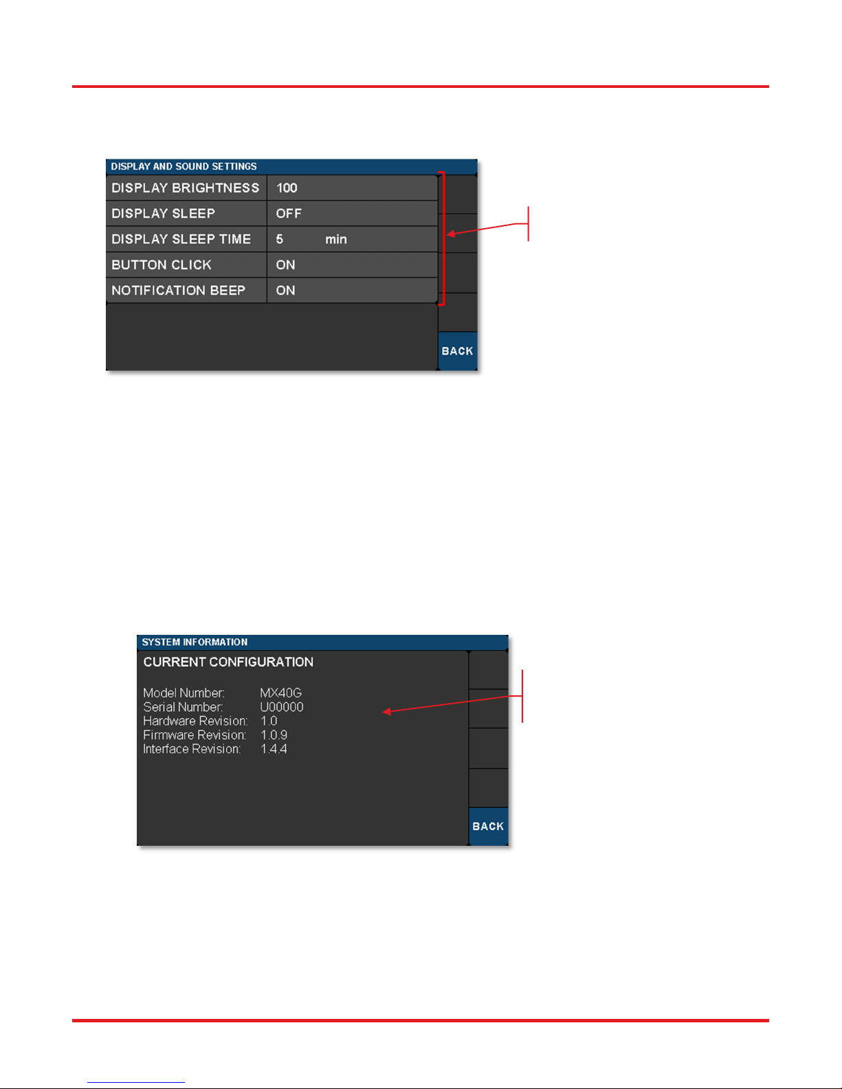
Toopenthescreenshownbelow,taptheDISPLAYANDSOUNDSbuttonontheMenupane.
Tap any of the fields to access
the respective controls.
Figure 41 Display and Sound Settings Page
DISPLAY BRIGHTNESS controls the overall brightness of the touch-screen display
DISPLAY SLEEP TIME controls how long the touch-screen display is visible before it sleeps
BUTTON CLICK toggles the sound produced when tapping buttons (On/Off)
NOTIFICATION BEEP toggles the sound associated with certain on screen notifications (On/Off)
4.8.3 System Information Page
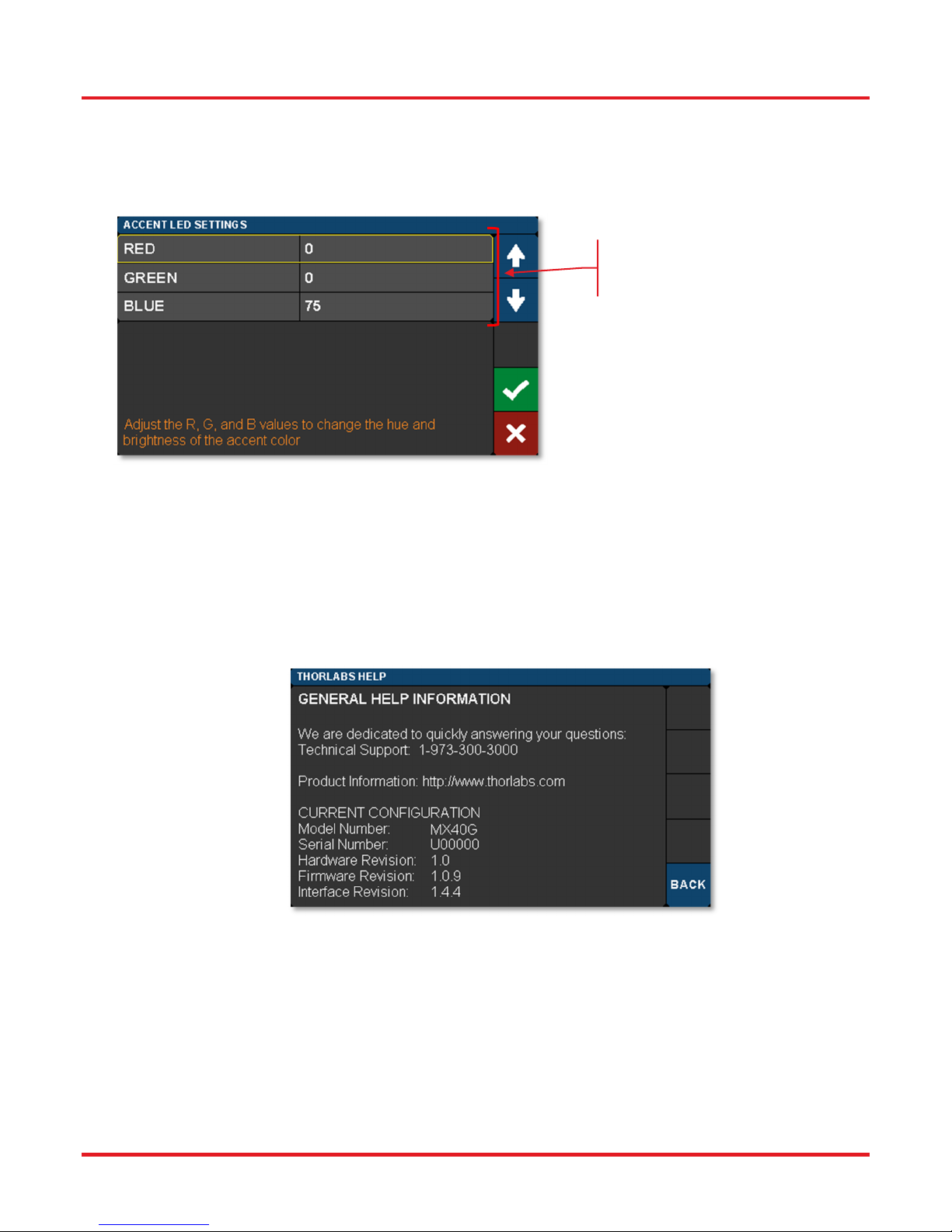
To open the screen shown below, tap the SYSTEM INFORMATION button on the Menu pane.
The System Information page displays the installed hardware and software versions.
This is useful information when in
the need for tech support or to
verify firmware revisions.
Figure 42 System Information Page
Page 26 TTN116413-D02
Page 31
MX40G, MX70G Series of E-O Converters Chapter 4: Operating Instructions
4.8.4 Accent LED Settings Page
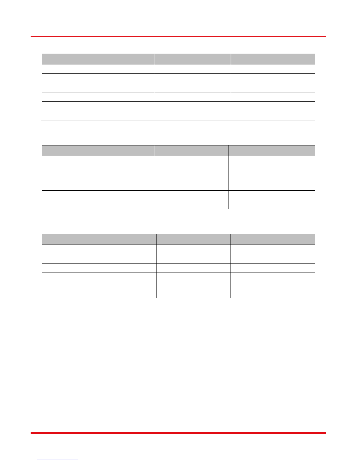
To open the screen shown below, tap the ACCENT LEDS button on the Menu pane.
The accent LED settings control the intensity of the color LEDs that emanate from the bottom of the instrument. These are a
fun aesthetic feature. You can set them to your favorite color.
Tap any of the three color fields to
access the up/down controls.
Learn to mix colors!
Figure 43 Controls to Adjust the LEDs Providing the Under-Instrument Accent Light
4.8.5 Thorlabs Help Page
To open the screen shown below, tap the THORLABS HELP button on the Menu pane.
The Thorlabs Help page displays the Tech Support phone number, Thorlabs web site, and the installed hardware and software
versions. This information will be useful when speaking with Tech Support.
Figure 44 Thorlabs Help Page
Rev. E, March 19, 2019 Page 27
Page 32

MX40G, MX70G Series of E-O Converters Chapter 5: Specifications
Chapter 5 Specifications
All Specifications are at 1550 nm and 25 °C ambient temperature, unless otherwise noted. Specifications that are specific to
models in the MX40G or MX70G series will be marked as such.
5.1 General System Specifications
Parameter Typical Values Notes
Laser Output Power
Optical Input Power
MX40G, MX70G C-Band Tunable in 50 GHz Steps
Internal Laser
Wavelength
1
Range
MX40G-LB,
MX70G-LB
MX40G-1310,
MX70G-1310
External Laser Wavelength Range2
Calibrated Wavelengths
Optical Extinction Ratio
Input RF
Connector Type
Frequency
Response
5
Uncertainty of
MX40G Series 2.92 mm Connector
MX70G Series 1.85 mm Connector4
MX40G Series DC - 40 GHz
MX70G Series DC - 70 GHz
MX40G Series ±0.85 dB From 40 MHz to 40 GHz
Supplied
Magnitude
Response
6
MX70G Series
Modulator RF Input
Optical Insertion Loss
Absolute Stability8
Relative Stability8
1310 nm, 1550 nm, 1590 nm User Selectable
±1 V Max for Linear Response
13.5 dBm Max From Internal Laser
20 dBm Max
From External Laser,
22 dBm Absolute Max
L-Band Tunable in 50 GHz Steps
1310 nm Fixed-Wavelength
1250 nm - 1610 nm -
13 dB Max -
3
-
-
±0.85 dB From 40 MHz to 40 GHz
±1.75 dB From 40 GHz to 70 GHz
7
±5 V Absolute Max
5.0 dB at 1550 nm
7.0 dB at 1310 nm
0.1 dB (Dither Mode)
0.2 dB (Ratio Mode)
Laser IN to Optical OUT
Stability of Modulation
Amplitude at any Single
Frequency Point
Stability of Modulation
0.02 dB (Dither Mode)
0.02 dB (Ratio Mode)
Amplitude Between
Frequency Points
(Response Shape)
1
An 850 nm fixed-wavelength laser can be substituted upon request: contact Thorlabs’ technical support.
2
Using the modulator at another wavelength (e.g. visible light) may cause an increase in insertion loss and will void the
warranty.
3
The 2.92 mm connector can mate directly to an SMA, 3.5 mm, or K connector.
4
The 1.85 mm connector can mate directly to a 2.4 mm or V connector.
5
Measured frequency response provided in *.s2p file on a USB drive with each unit.
6
At each frequency specified in the frequency response file.
7
With Bias Point at Quadrature
8
For a temperature range of 3 °C and a time period of 4 hours.
Page 28 TTN116413-D02
Page 33
MX40G, MX70G Series of E-O Converters Chapter 5: Specifications
5.2 Power and Environmental Specifications
Parameter Min Max
Main AC Voltage
Power Consumption
Line Frequency
Operating Temperature
Storage Temperature
Relative Humidity
100 VAC 250 VAC
- 60 VA
50 Hz 60 Hz
10 °C 40 °C
0 °C 50 °C
5% 85%
5.3 Internal Control Specifications
Parameter Typical Notes
Power Monitors Accuracy
Power Monitors Resolution
Power Monitor Insertion Loss
VOA Insertion Loss
VOA Response Time
±0.5 dBm
0.01 dBm Each Monitor
0.1 dB Typical Per Monitor
0.4 dB Typical -
1 s -
Each Monitor, At Calibrated
Wavelength
5.4 Internal Modulator Specifications
Parameter Typical Values Notes
Electro-Optic
Bandwidth
DC Optical On/Off Extinction Ratio
RF Drive Voltage (Vpi)
Insertion Loss
MX40G Series 40 GHz
MX70G Series 70 GHz
20 dB -
5.5 V
pp
4.0 dB at 1550 nm
6.0 dB at 1310 nm
At 1 GHz
-
-
Rev. E, March 19, 2019 Page 29
Page 34

MX40G, MX70G Series of E-O Converters Chapter 5: Specifications
5.5 Laser Specifications
Parameter Unit Min Typ. Max
C-Band Tunable Laser (MX40G, MX70G)
Optical Output Power
Frequency Range
Wavelength Range
Frequency Accuracy
Tuning Resolution
Tuning Speed (Between Wavelengths)
Side Mode Suppression Ratio (SMSR)
Optical Signal to Noise Ratio (OSNR)
Intrinsic Linewidth
Relative Intensity Noise (RIN)
Back Reflection
Polarization Extinction Ratio (PER)
L-Band Tunable-Laser (MX40G-LB, MX70G-LB)
Optical Output Power
Frequency Range
Wavelength Range
Frequency Accuracy
Tuning Resolution
Tuning Speed (Between Wavelengths)
SMSR
OSNR
Intrinsic Linewidth
RIN
Back Reflection
PER
1310 nm Fixed-Wavelength Laser (MX40G-1310, MX70G-1310)
Optical Output Power
Wavelength
SMSR
Intrinsic Linewidth
PER
dBm 12.5 13.5 14.5
THz 191.50 - 196.25
nm 1527.6 - 1565.5
GHz -1.5 - 1.5
GHz - 50 -
s - 10 -
dB 40 55 -
dB 40 60 -
kHz - 10 15
dB/Hz - - -145
dB - - -14
dB 18 - -
dBm 12.5 13.5 14.5
THz 186.35 - 190.95
nm 1570.0 - 1608.8
GHz -1.5 - 1.5
GHz - 50 -
s - 10 -
dB 40 55 -
dB 40 60 -
kHz - 10 15
dB/Hz - - -145
dB - - -14
dB 18 - -
dBm 12.5 13.5 14.5
nm - 1310 -
dB 35 - -
MHz - 2 3
dB - 20 -
Page 30 TTN116413-D02
Page 35
MX40G, MX70G Series of E-O Converters Chapter 6: Control and PC Connections
Chapter 6 Control and PC Connections
6.1 General Purpose I/O, RS-232, and USB Connections
The back panel has connectors for monitor and control functions, as well as for upgrading the firmware. Both the RS-232 and
the USB connections can be used for remotely controlling the MX40G and MX70G converters via SCPI type serial commands.
Which connector to choose for remote control operation depends on the demands of the application and the user’s preference.
See the remote control user guide (RCUG), which can be downloaded from https://www.thorlabs.com/manuals.cfm, for
information about the commands and connecting the unit to a PC.
The most recent firmware and remote control software tools are available from Thorlabs' website at
https://www.thorlabs.com/software_pages/viewsoftwarepage.cfm?code=MXG. The instrument’s firmware can be updated by
uploading the new version from a PC via the USB port. Thorlabs’ technical support can provide up-to-date information on
available firmware revisions and control functions.
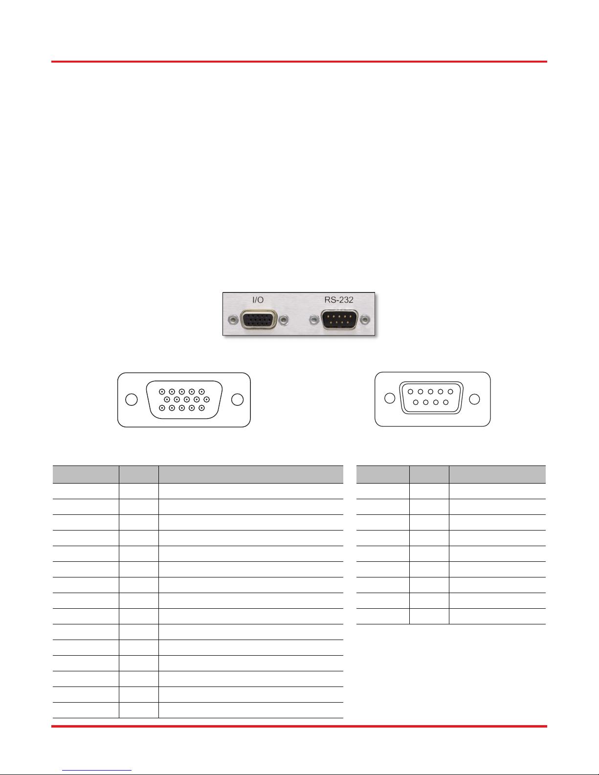
The 15-pin I/O connector provides outputs from the power monitors in the optical path (see the block diagram in Chapter 3). The
power monitors provide a voltage that is proportional to the optical power with one of two gain settings. These values are
available on the I/O DB15 connector. The gain setting for each monitor is determined by software, and reported on the
corresponding Gain Indicator pins. 0.0 V indicates Low Gain (40 V/W) and 3.3 V indicates High Gain (4000 V/W). Maximum
output voltage at the monitor pin is less than 12 V (into a high impedance). Power monitor bandwidth is limited to about 150 Hz.
Figure 45 15-Pin I/O and RS-232 Connectors on the Back Panel
5
10
15 11
Figure 46 15-Pin I/O Connector Pin Configuration
1
6
Figure 47 RS-232 Connector Pin Configuration
1 2 3 4 5
6 7 8 9
I/O Conn. Pin # Description RS-232 Pin # Description
HD DB15 1 Power Monitor 1 (Mon-1) DB9 1 Not Connected
HD DB15 2 Power Monitor 2 (Mon-2) DB9 2 RS-232 Input
HD DB15 3 Power Monitor 3 (Mon-3) DB9 3 RS-232 Output
HD DB15 4 Reserved for Future Use DB9 4 Not Connected
HD DB15 5 Analog Ground DB9 5 Digital Ground
HD DB15 6 Analog Ground DB9 6 Not Connected
HD DB15 7 Analog Ground DB9 7 Not Connected
HD DB15 8 Analog Ground DB9 8 Not Connected
HD DB15 9 Analog Ground DB9 9 Not Connected
HD DB15 10 Analog Ground
HD DB15 11 Reserved for Future Use
HD DB15 12 Reserved for Future Use
HD DB15 13 Power Monitor 1 (Mon-1) Gain Indicator
HD DB15 14 Power Monitor 2 (Mon-2) Gain Indicator
HD DB15 15 Power Monitor 3 (Mon-3) Gain Indicator
Rev. E, March 19, 2019 Page 31
Page 36
MX40G, MX70G Series of E-O Converters Chapter 6: Control and PC Connections
6.2 The Laser Safety Interlock
The laser is equipped with a phono-type interlock jack located on the back panel. To enable the laser source, a short circuit
must be applied across the terminals of the interlock connector. The shorting device (interlock pin) installed in all units shipped
from Thorlabs performs this function. Leave the shorting device installed unless using an external safety circuit or other type of
remotely controlled switch to enable laser output.
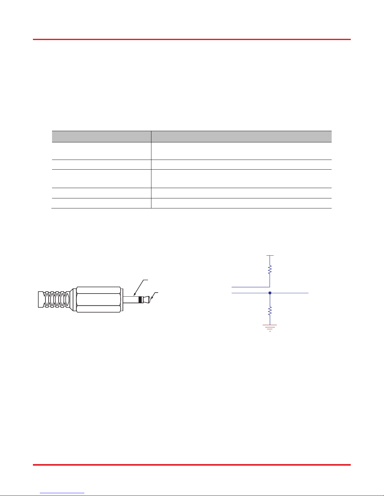
Making use of the Interlock feature requires the appropriate 2.5 mm phono-type plug, which is diagrammed in Figure 48(a) and
is readily available through most electronics retailers. The plug should be wired to the external safety circuit or switch and then
plugged into the back panel’s interlock jack in place of the shorting device. The electrical specifications of the interlock jack are
listed in the following table, and the circuit schematic describing how the interlock jack is connected inside the laser head is
shown in Figure 48(b).
Specification Value
Interlock Switch Requirements
Type of Mating Connector
Open Circuit Voltage
Short Circuit Current (Typical)
Connector Polarity
Must be Normally Open Dry Contacts
Apply no External Voltages to the Interlock Input
2.5 mm Mono Phono Jack
<5 VDC
(Center Pin is at 5 VDC, Ring is Ground)
7 mA
Tip is Ground, Barrel is at 5 VDC Max
The user’s safety circuit must be attached to the phono plug and wired such that the ring and center pin are shorted when it is
safe to enable the laser. The laser will be enabled when connection is closed. If it changes to an open state, the laser source
will turn off.
+5.0 V
1.00 kΩ
Ring
Center Pin
Center Pin
Ring
(a) Diagram of a Phono-Type Plug (b) Internal Electrical Connections of the Interlock Jack
Figure 48 The interlock circuitry internal to the laser head applies a 5 VDC bias across the ring and center pin
of the plug. An external circuit that shorts the ring and center pin enables the laser.
GND
10.0 kΩ
Page 32 TTN116413-D02
Page 37
MX40G, MX70G Series of E-O Converters Chapter 7: Mechanical Drawings
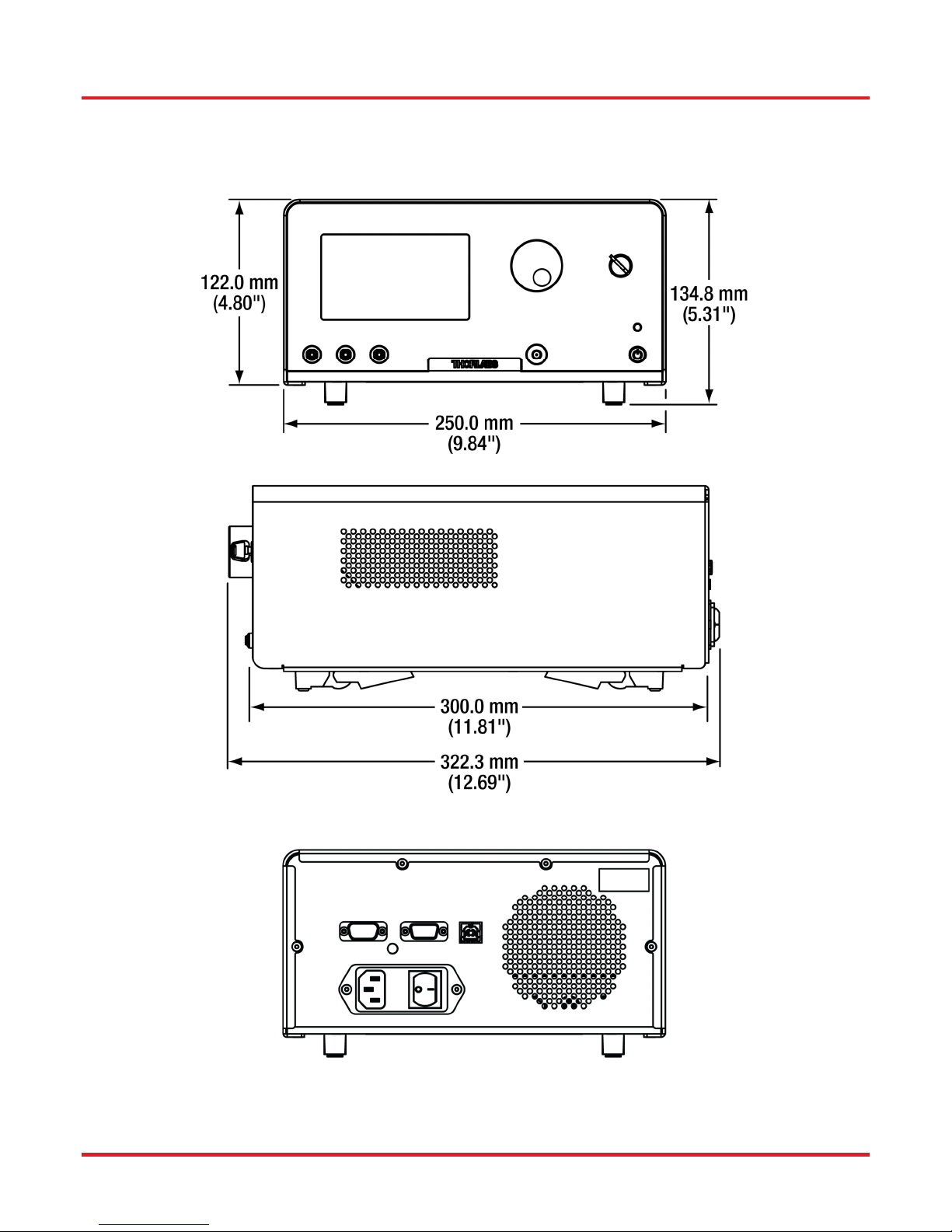
Chapter 7 Mechanical Drawings
Rev. E, March 19, 2019 Page 33
Figure 49 E-O Converter Mechanical Drawing
Page 38
MX40G, MX70G Series of E-O Converters Chapter 8: Maintenance, Repair, and Fuses
Chapter 8 Maintenance, Repair, and Fuses
8.1 Maintenance and Repair
The instrument should not need regular maintenance by the user. If necessary the display, housing, and front panel can be
cleaned using a soft cloth moistened with normal, mild glass cleaner. Do not use any chemical solvents or harsh cleaners on
the display. Do not spray any cleaning solutions directly onto any part of the unit.
The instrument does not contain any modules that can be repaired by the user. If a malfunction occurs, please contact Thorlabs
Technical Support and arrangements will be made to investigate the problem. Do not remove the cover. There are no user
serviceable components inside.
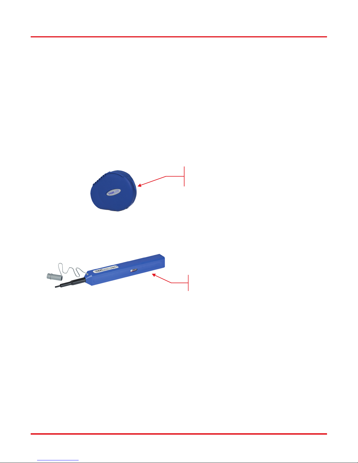
Optical patch cords used to connect to the front panel of the instrument should have their end faces cleaned every time a new
connection is made. The end faces of the internal fiber connectors can easily be damaged by the use of dirty fiber ends. If
damage occurs, the instrument will need to be sent back for repair. We suggest using a fiber end-face cleaning product such as
the Thorlabs FCC-7020 shown below. Alternatively, a lint-free cloth moistened with isopropyl alcohol or methanol can be used.
Never use acetone.
Thorlabs FCC-7020
Fiber End-Face Cleaner for Patch Cords
The optical connectors on the front panel may be cleaned using a 2.5 mm bulkhead cleaner such as the Thorlabs FBC1. This
allows the user to clean the fiber end-face without removing it from the internal bulkhead adapter.
Thorlabs FBC1
Fiber End-Face Cleaner for Bulkheads
8.2 Replacement Parts
The following parts can be obtained by contacting Thorlabs Technical Support
SMA 50 Ω Loads (Used for Front Panel RF Connectors)
PM Loopback Fiber Patch Cord for Front Panel
Laser Interlock Keys for Front Panel Switch
2.5 mm Interlock Pin (for Back Panel)
1.25 A 250 VAC Fuse for Main Power
Instrument IEC Main Power Cord
Instrument Flip Foot
Page 34 TTN116413-D02
Page 39
MX40G, MX70G Series of E-O Converters Chapter 8: Maintenance, Repair, and Fuses
8.3 Replacing the Main Fuse
The system is protected by a main fuse located in the power entry module where the main power cable plugs into the back
panel of the instrument. If the instrument does not appear to power-up, especially after a power outage or storm, you can
check the condition of the main power fuse without removing the cover of the instrument by following the following steps.
1. Put the instrument in “Standby” mode by pressing the standby button on the front of the instrument.
Wait until the button turns from green to amber.
2. Turn the power off using the switch on the back panel of the instrument.
3. Unplug the main power cable.
4.
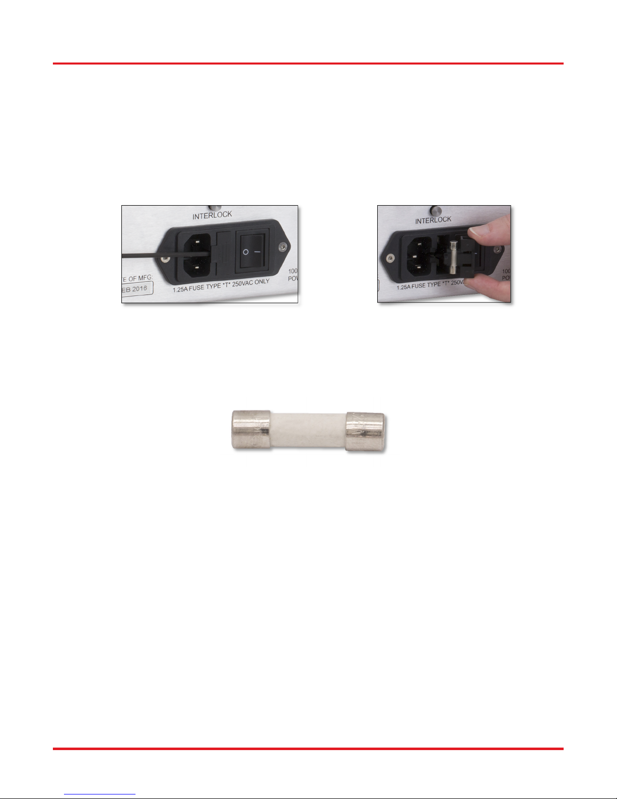
Carefully remove the fuse holder slide from the power entry module (use a flat screwdriver)
.
Figure 50
Power Entry Module
Figure 51
Removing the Fuse Holder Slide
Investigate the fuse. This can be done with a simple continuity check. If in doubt, replace the fuse. A spare fuse is stored in the
fuse holder. Additional replacement fuses can be purchased from Thorlabs. Always use fuses of the same type as the
original.
Figure 52 Fuse
1. Reinstall the fuse holder slide into the power entry module, taking care that it fully seats until the top is flush with the
rest of the power entry module.
2.
Plug the main power cable back into the unit and power on as described in the Getting Started section of the manual.
If the fuse blows repeatedly, it is likely that an internal failure has occurred. Do not attempt to bypass the fuse as this can create
a dangerous situation that could further damage the instrument or harm personnel. In this case, please contact Technical Support
for directions.
Rev. E, March 19, 2019 Page 35
Page 40

MX40G, MX70G Series of E-O Converters Chapter 9: Troubleshooting
Chapter 9 Troubleshooting
Below is some information about status indicators and a few checks to help in troubleshooting general problems. If you have
any questions, please contact your local Thorlabs Technical Support office.
If the unit does not appear to turn on correctly, please check the following items:
Ensure that the main AC receptacle is powered
Ensure that main power cable is fully seated at both ends
Ensure that back power switch is in the “I” position
Check the main power fuse (see Maintenance and Repair Section)
The color of the Standby Button, which is on the front panel, indicates several status conditions as follows:
Standby Button Color Condition
Solid Green
Solid Amber
Blinking Green
Blinking Amber
Blinking Amber/Green
Fading Amber/Green
Indicates normal ON state.
Indicates unit is in Standby Mode.
Press the button to turn the instrument ON.
Indicates the main AC power is unstable. When the AC power is
restored, the instrument will return to the standby mode (amber).
Indicates the instrument is overheated. Make sure the fan is running
and none of the vents are blocked. If there are no ventilation issues,
then the box should cool itself and return to the standby.
Do not operate, or leave the instrument in standby mode, in an
environment above 40 °C.
Indicates the instrument is both overheated and the main AC power is
unstable (see individual troubleshooting for these conditions above).
Indicates the instrument is in the firmware upgrade mode.
If this condition appears after attempting to upgrade the firmware, the
update may have failed, or the unit may have been left in the update
mode. Try running the firmware update again.
This condition may have also been reached by holding down the
standby button for a long time while turning on the power. In this case,
turn the unit off, wait for a few seconds, and turn it back on.
If this condition for any other reason, turn the unit off, wait for a few
seconds, and turn it back on.
If these attempts to recover continue to fail, the instrument’s firmware
may have been corrupted. Contact Tech Support for help.
If the optical power at any point of the system is lower than expected, resolving the problem always starts by cleaning the
optical fiber ends. Contaminated fiber ends, which attenuates the intensity of the transmitted light, is a very common issue when
using single-mode fibers. Follow the suggestions provided in the Maintenance and Repair section of this manual to clean the
optical fiber ends.
Page 36 TTN116413-D02
Page 41
MX40G, MX70G Series of E-O Converters Chapter 10: Declaration of Conformity
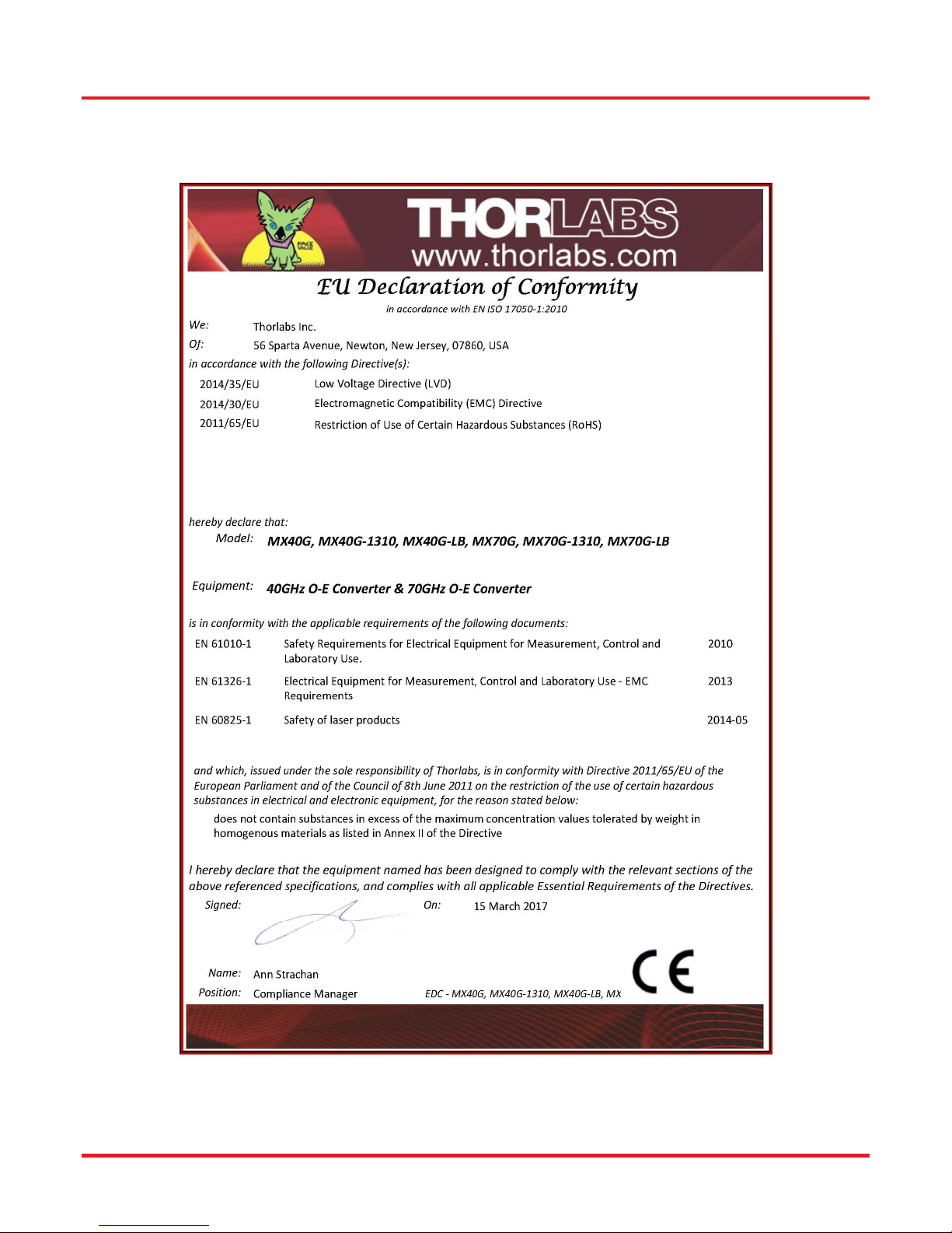
Chapter 10 Declaration of Conformity
Rev. E, March 19, 2019 Page 37
Page 42

MX40G, MX70G Series of E-O Converters Chapter 11: Thorlabs Worldwide Contacts
Chapter 11 Thorlabs Worldwide Contacts
USA, Canada, and South America
Thorlabs, Inc.
56 Sparta Avenue
Newton, NJ 07860
USA
Tel: 973-300-3000
Fax: 973-300-3600
www.thorlabs.com
www.thorlabs.us (West Coast)
Email: [email protected]
Support: [email protected]
Europe
Thorlabs GmbH
Hans-Böckler-Str. 6
85221 Dachau
Germany
Tel: +49-(0)8131-5956-0
Fax: +49-(0)8131-5956-99
www.thorlabs.de
Email: [email protected]
France
Thorlabs SAS
109, rue des Côtes
78600 Maisons-Laffitte
France
Tel: +33 (0) 970 444 844
Fax: +33 (0) 825 744 800
www.thorlabs.com
Email: [email protected]
UK and Ireland
Thorlabs Ltd.
1 Saint Thomas Place, Ely
Cambridgeshire CB7 4EX
Great Britain
Tel: +44 (0)1353-654440
Fax: +44 (0)1353-654444
www.thorlabs.com
Email: [email protected]
Support: [email protected]
Scandinavia
Thorlabs Sweden AB
Bergfotsgatan 7
431 35 Mölndal
Sweden
Tel: +46-31-733-30-00
Fax: +46-31-703-40-45
www.thorlabs.com
Email: [email protected]
Brazil
Thorlabs Vendas de Fotônicos Ltda.
Rua Riachuelo, 171
São Carlos, SP 13560-110
Brazil
Tel: +55-16-3413 7062
Fax: +55-16-3413 7064
www.thorlabs.com
Email: [email protected]
Japan
Thorlabs Japan, Inc.
3-6-3 Kitamachi,
Nerima-ku, Tokyo 179-0081
Japan
Tel: +81-3-6915-7701
Fax: +81-3-6915-7716
www.thorlabs.jp
Email: [email protected]
China
Thorlabs China
Room A101, No. 100
Lane 2891, South Qilianshan Road
Putuo District
Shanghai
China
Tel: +86 (0) 21-60561122
Fax: +86 (0)21-32513480
www.thorlabschina.cn
Email: [email protected]
Thorlabs verifies our compliance with the WEEE (Waste Electrical and Electronic Equipment) directive of
the European Community and the corresponding national laws. Accordingly, all end users in the EC may
return “end of life” Annex I category electrical and electronic equipment sold after August 13, 2005 to
Thorlabs, without incurring disposal charges. Eligible units are marked with the crossed out “wheelie bin”
logo (see right), were sold to and are currently owned by a company or institute within the EC, and are
not dissembled or contaminated. Contact Thorlabs for more information. Waste treatment is your own
responsibility. “End of life” units must be returned to Thorlabs or handed to a company specializing in
waste recovery. Do not dispose of the unit in a litter bin or at a public waste disposal site.
Page 38 TTN116413-D02
Annex I
Page 43

Page 44

www.thorlabs.com
 Loading...