

Page 1

Artisan Technology Group is your source for quality
new and certied-used/pre-owned equipment
• FAST SHIPPING AND
DELIVERY
• TENS OF THOUSANDS OF
IN-STOCK ITEMS
• EQUIPMENT DEMOS
• HUNDREDS OF
MANUFACTURERS
SUPPORTED
• LEASING/MONTHLY
RENTALS
• ITAR CERTIFIED
SECURE ASSET SOLUTIONS
SERVICE CENTER REPAIRS
Experienced engineers and technicians on staff
at our full-service, in-house repair center
Instra
Remotely inspect equipment before purchasing with
our interactive website at www.instraview.com
Contact us: (888) 88-SOURCE | [email protected] | www.artisantg.com
SM
REMOTE INSPECTION
View
WE BUY USED EQUIPMENT
Sell your excess, underutilized, and idle used equipment
We also offer credit for buy-backs and trade-ins
www.artisantg.com/WeBuyEquipment
LOOKING FOR MORE INFORMATION?
Visit us on the web at www.artisantg.com for more
information on price quotations, drivers, technical
specications, manuals, and documentation
Page 2
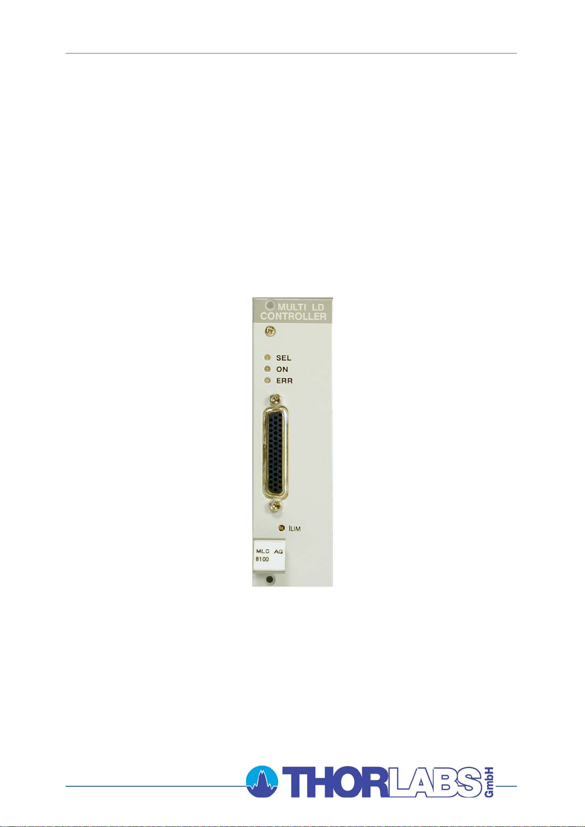
Operation Manual
Thorlabs Blueline™ Series
PRO8000 (-4) / PRO800
Multi laser controller module MLC8xxx
Artisan Technology Group - Quality Instrumentation ... Guaranteed | (888) 88-SOURCE | www.artisantg.com
2004
Page 3

Version: 2.10
Date: 22.01.2004
Copyright© 2004, Thorlabs GmbH
Artisan Technology Group - Quality Instrumentation ... Guaranteed | (888) 88-SOURCE | www.artisantg.com
Page 4

Contents Page
1 General description of the multi LD-controller MLC8xxx 1
1.1 Safety 1
1.2 Warranty 3
1.3 Features 4
1.3.1 Safety measures for the laser diode 4
1.3.2 General functions 6
1.4 Technical data 7
1.4.1 MLC8025-8 7
1.4.2 MLC8050-8 7
1.4.3 MLC8100-8 8
1.4.4 MLC8200-8 8
1.5 Operating elements at the front of the module 9
1.6 Pre-settings 10
1.6.1 Setting hardware limit I
10
LIM
1.7 Connecting components (Anode Ground Version) 11
1.7.1 Pinning of the output connector 11
1.7.2 Pin assignment MLC8xxx 12
1.7.3 Connecting laser- and monitor diode 17
1.7.4 Standard configurations, no bias voltage 18
1.7.5 Standard configurations with bias voltage 5V 19
1.7.6 Connecting interlock and status display 21
1.8 Connecting components (Cathode Ground Version) 22
1.8.1 Pinning of the output connector 22
1.8.2 Pin assignment MLC8xxx 23
1.8.3 Connecting laser- and monitor diode 28
1.8.4 Standard configurations without bias voltage 29
1.8.5 Standard configurations with bias voltage 5V 31
1.8.6 Connecting interlock and status display 32
2 Operating the MLC8xxx 33
2.1 Functions in the main menu 33
2.1.1 Display 33
2.1.2 Selecting a module 34
2.2 Functions in the channel menu 35
2.2.1 Display 35
2.2.2 Changing parameters 37
2.2.3 Selecting the laser diode current range 38
Artisan Technology Group - Quality Instrumentation ... Guaranteed | (888) 88-SOURCE | www.artisantg.com
Page 5

2.2.4 Selecting constant current or constant power mode 38
2.2.5 Selecting a TEC module for temperature protection 40
2.2.6 Activating the temperature protection 40
2.3 Switching on and off 41
2.4 Error messages 42
3 Communicating with a control computer 44
3.1 General notes on remote control 44
3.1.1 Nomenclature 45
3.1.2 Data format 45
3.2 Commands 47
3.2.1 Select the module slot 47
3.2.2 Selecting the channel (PORT) 47
3.2.3 Setting the laser diode current (ILD) 48
3.2.4 Changing the monitor diode current (IMD) 50
3.2.5 Switching the output on and off (LASER) 52
3.2.6 Reading the laser diode hardware limit (LIMCP) 52
3.2.7 Selecting the operation mode (MODE) 53
3.2.8 Setting the current range (RANGE) 53
3.2.9 Activating the temperature protection (TP) 54
3.2.10 Assigning a TEC for temperature protection (TPSLOT) 54
3.2.11 Reading type of module (TYPE) 55
3.3 Error messages of an MLC8xxx 56
3.4 Status reporting. 58
3.4.1 Standard event status register (ESR) 60
3.4.2 Standard event status enable register (ESE) 60
3.4.3 Status byte register (STB) 61
3.4.4 Service request enable register (SRE) 61
3.4.5 Reading the STB by detecting SRQ 62
3.4.6 Reading the STB by "*STB?" command 62
3.4.7 Reading the STB by serial poll 62
3.4.8 Device error condition register (DEC) 63
3.4.9 Device error event register (DEE) 63
3.4.10 Device error event enable register (EDE) 64
4 Service and Maintenance 65
4.1 General remarks 65
4.2 Troubleshooting 66
5 Listings 69
5.1 List of abbreviations 69
5.2 List of figures 71
Artisan Technology Group - Quality Instrumentation ... Guaranteed | (888) 88-SOURCE | www.artisantg.com
Page 6

5.3 Certifications and compliances 72
5.4 Addresses 73
Artisan Technology Group - Quality Instrumentation ... Guaranteed | (888) 88-SOURCE | www.artisantg.com
Page 7

We aim to develop and produce the best solution for your application in the
field of optical measurement technique. To help us to come up to your
expectations and develop our products permanently we need your ideas and
suggestions. Therefore, please let us know about possible criticism or ideas.
We and our international partners are looking forward to hearing from you.
In the displays shown by the PRO8 you may find the name PROFILE.
PROFILE was the name of the manufacturer before it was acquired by Thorlabs
and renamed to Thorlabs GmbH.
Thorlabs GmbH
This operation manual contains every specific information on how to operate a multi
laser diode controller module MLC8xxx. A general description is followed by
explanations of how to operate the unit manually. You will also find every information
about remote control via the IEEE 488 computer interface.
Attention
This manual contains “WARNINGS” and “ATTENTION” label in this
form, to indicate dangers for persons or possible damage of equip-
ment.
Please read these advises carefully!
NOTE
This manual also contains “NOTES” and “HINTS” written in this form.
Artisan Technology Group - Quality Instrumentation ... Guaranteed | (888) 88-SOURCE | www.artisantg.com
Page 8

1.1 Safety
1 General description of the multi LD-controller MLC8xxx
1.1 Safety
Attention
All statements regarding safety of operation and technical data in
this instruction manual will only apply when the unit is operated
correctly.
Before applying power to your PRO8000 (-4) / PRO800 system, make
sure that the protective conductor of the 3 conductor mains power
cord is correctly connected to the protective earth contact of the
socket outlet!
Improper grounding can cause electric shock with damages to your
health or even death!
Modules may only be installed or removed with the mainframe
switched off.
All modules must be fixed with all screws provided for this purpose.
Modules of the 8000 series must only be operated in the mainframe
PRO8000, PRO8000-4 or PRO800.
All modules must only be operated with duly shielded connection
cables.
Only with written consent from Thorlabs may changes to single
components be carried out or components not supplied by Thorlabs
be used.
This precision device is only dispatchable if duly packed into the
complete original packaging including the plastic form parts. If
necessary, ask for a replacement package.
MLC8xxx / page 1
Artisan Technology Group - Quality Instrumentation ... Guaranteed | (888) 88-SOURCE | www.artisantg.com
Page 9

1.1 Safety
Attention
Semiconductor laser modules can deliver up to several 100mW of
(maybe) invisible laser radiation!
When operated incorrectly, this can cause severe damage to your
eyes and health!
Be sure to pay strict attention to the safety recommendations of the
appropriate laser safety class!
This laser safety class is marked on your PRO8000 (-4) / PRO800
plug-in module or on your external laser source used.
Attention
Mobile telephones, handy phones or other radio transmitters are not
to be used within the range of three meters of this unit since the
electromagnetic field intensity may then exceed the maximum
allowed disturbance values according to EN 50 082-1.
MLC8xxx / page 2
Artisan Technology Group - Quality Instrumentation ... Guaranteed | (888) 88-SOURCE | www.artisantg.com
Page 10

1.2 Warranty
1.2 Warranty
Thorlabs GmbH warrants material and production of the MLC8xxx modules for a
period of 24 months starting with the date of shipment. During this warranty period
Thorlabs GmbH will see to defaults by repair or by exchange if these are entitled to
warranty.
For warranty repairs or service the unit must be sent back to Thorlabs GmbH
(Germany) or to a place determined by Thorlabs GmbH. The customer will carry the
shipping costs to Thorlabs GmbH, in case of warranty repairs Thorlabs GmbH will
carry the shipping costs back to the customer.
If no warranty repair is applicable the customer also has to carry the costs for back
shipment.
In case of shipment from outside EU duties, taxes etc. which should arise have to be
carried by the customer.
Thorlabs GmbH warrants the hard- and software determined by Thorlabs GmbH for
this unit to operate fault-free provided that they are handled according to our
requirements. However, Thorlabs GmbH does not warrant a faulty free and
uninterrupted operation of the unit, of the soft- or firmware for special applications nor
this instruction manual to be error free. Thorlabs GmbH is not liable for consequential
damages.
Restriction of warranty
The warranty mentioned before does not cover errors and defects being the result of
improper treatment, software or interface not supplied by us, modification, misuse or
operation outside the defined ambient conditions (refer to the PRO8000(-4) /
PRO800 mainframe operation manual) stated by us or unauthorized maintenance.
Further claims will not be consented to and will not be acknowledged. Thorlabs
GmbH does explicitly not warrant the usability or the economical use for certain
cases of application.
Thorlabs GmbH reserves the right to change this instruction manual or the technical
data of the described unit at any time.
MLC8xxx / page 3
Artisan Technology Group - Quality Instrumentation ... Guaranteed | (888) 88-SOURCE | www.artisantg.com
Page 11

1.3 Features
1.3 Features
1.3.1 Safety measures for the laser diode
To protect the connected laser diodes the MLC8xxx modules contain the following
protection circuits:
• Softstart when switching on the laser diode current
Protection against capacitive and inductive parasitic elements (switching peaks).
• Limit for the injection current in all operating modes
Protection against thermal destruction of the laser chip.
• Limit for the optical power in constant current (!) mode
Protection against thermal destruction of the mirrors caused by too high optical
power.
• Interruption control of the connection cable to the laser diode (interlock)
Protection against accidental operation.
• Electronic short-circuit switch for the laser diode
Protection against static discharge when touching the switched off laser.
• Separate on and off function for each module
Protection against operating errors.
• Control LED for activated laser current
Laser protection when laser radiation is switched on.
• Separate over-temperature protection for each module
Protection against thermal failure of the module.
• Mains filter
Protection against line transients.
MLC8xxx / page 4
Artisan Technology Group - Quality Instrumentation ... Guaranteed | (888) 88-SOURCE | www.artisantg.com
Page 12

1.3 Features
• Line failure protection
In case of power failure or line damage the current module must explicitly be
switched on anew since it cannot be taken for granted that all components of the
measurement set-up are still working reliably.
• Key-operated power switch
Protection against unauthorized or accidental use.
• LabVIEW®- and LabWindows/CVI®-driver
For the PRO8000 (-4) / PRO800 Thorlabs supplies LabVIEW®- and LabWin-
dows/CVI®-drivers for MS Windows 32.
Please refer to our homepage for latest driver updates.
http://www.thorlabs.com
MLC8xxx / page 5
Artisan Technology Group - Quality Instrumentation ... Guaranteed | (888) 88-SOURCE | www.artisantg.com
Page 13

1.3 Features
1.3.2 General functions
The current modules MLC8xxx are unipolar current sources for laser diodes.
They can be ordered for laser diodes with anode grounded or cathode grounded. The
MLC offers two current ranges.
The different module types operate the same way, they only differ in maximum
current, resolution and accuracy.
(Refer to chapter 1.4, "Technical data" starting on page 7)
The current modules MLC8xxx contain a monitor diode input realized as trans-
impedance amplifier (input impedance 0 Ω). Both polarities of the monitor diode are
allowed. The monitor diode may be driven either photovoltaic (without bias voltage)
or photoconductive, i.e. with bias voltage (U
= 5V).
BIA
All necessary value settings are done by the mainframe operating elements (keypad
and rotational encoder) or via remote control by a computer. Only the laser diode
current limit (hardware limit) has to be set manually as "absolute limit".
In an automated test set-up for different laser diodes no manual settings are
required.
All outputs can operate either in constant current or constant power mode
simultaneously. All outputs are switched on and off together.
With the modules MLC8xxx the laser diode current (constant current mode) or the
monitor diode current (constant power mode) are set with 12 bit resolution.
The monitor diode current is read back with 12 bit, the laser diode current, laser
diode voltage and the limit for the laser diode current (hardware limit) with 11 bit plus
sign.
The built-in mains filter in the mainframe and the careful shielding of the transformer,
the micro processor as well as the module itself will provide an excellent suppression
of noise and ripple.
MLC8xxx / page 6
Artisan Technology Group - Quality Instrumentation ... Guaranteed | (888) 88-SOURCE | www.artisantg.com
Page 14

1.4 Technical data
1.4 Technical data
1.4.1 MLC8025-8AG/CG
Selectable range LOW HIGH
Current ranges 5 mA 25 mA
Setting accuracy ± 15 µA ± 75 µA
Setting- / measurement resolution 1.2 µA 6 µA
Noise without ripple (10Hz...10MHz) < 0.5 µA < 0.5 µA
Ripple (50Hz, rms) < 0.5 µA < 0.5 µA
Short term fluctuations (15s) < 0.15 µA < 0.3 µA
Drift (30min, 0...10Hz) < 0.3 µA < 1 µA
Setting range HW-Limit 0 ... ≥ 5 mA 0 ... ≥ 25 mA
Setting accuracy HW-Limit ± 50 µA ± 125 µA
Resolution HW-Limit 1.2 µA 6 µA
1.4.2 MLC8050-8AG/CG
Selectable range LOW HIGH
Current ranges 10 mA 50 mA
Setting accuracy ± 30 µA ± 150 µA
Setting- / measurement resolution 2.5 µA 12 µA
Noise without ripple (10Hz...10MHz) < 0.5 µA < 0.5 µA
Ripple (50Hz, rms) < 0.5 µA < 0.5 µA
Short term fluctuations (15s) < 0.25 µA < 0.5 µA
Drift (30min, 0...10Hz) < 0.5 µA < 1.5 µA
Setting range HW-Limit 0 ... ≥ 10 mA 0 ... ≥ 50 mA
Setting accuracy HW-Limit ± 100 µA ± 250 µA
Resolution HW-Limit 2.5 µA 12 µA
MLC8xxx / page 7
Artisan Technology Group - Quality Instrumentation ... Guaranteed | (888) 88-SOURCE | www.artisantg.com
Page 15

1.4 Technical data
1.4.3 MLC8100-8AG/CG
Selectable range LOW HIGH
Current ranges 25 mA 100 mA
Setting accuracy ± 75 µA ± 300 µA
Setting- / measurement resolution 6 µA 25 µA
Noise without ripple (10Hz...10MHz) < 0.5 µA < 1 µA
Ripple (50Hz, rms) < 0.5 µA < 1 µA
Short term fluctuations (15s) < 0.25 µA < 1 µA
Drift (30min, 0...10Hz) < 1 µA < 3 µA
Setting range HW-Limit 0 ... ≥ 25 mA 0 ... ≥ 100 mA
Setting accuracy HW-Limit ± 0.25 mA ± 0.5 mA
Resolution HW-Limit 6 µA 25 µA
1.4.4 MLC8200-8AG/CG
Selectable range LOW HIGH
Current ranges 50 mA 200 mA
Setting accuracy ± 150 µA ± 600 µA
Setting- / measurement resolution 12 µA 50 µA
Noise without ripple (10Hz...10MHz) < 0.5 µA < 1.5 µA
Ripple (50Hz, rms) < 0.5 µA < 1 µA
Short term fluctuations (15s) < 0.5 µA < 2 µA
Drift (30min, 0...10Hz) < 1.5 µA < 5 µA
Setting range HW-Limit 0 ... ≥ 50 mA 0 ... ≥ 200 mA
Setting accuracy HW-Limit ± 0.5 mA ± 1 mA
Resolution HW-Limit 12 µA 50 µA
MLC8xxx / page 8
Artisan Technology Group - Quality Instrumentation ... Guaranteed | (888) 88-SOURCE | www.artisantg.com
Page 16
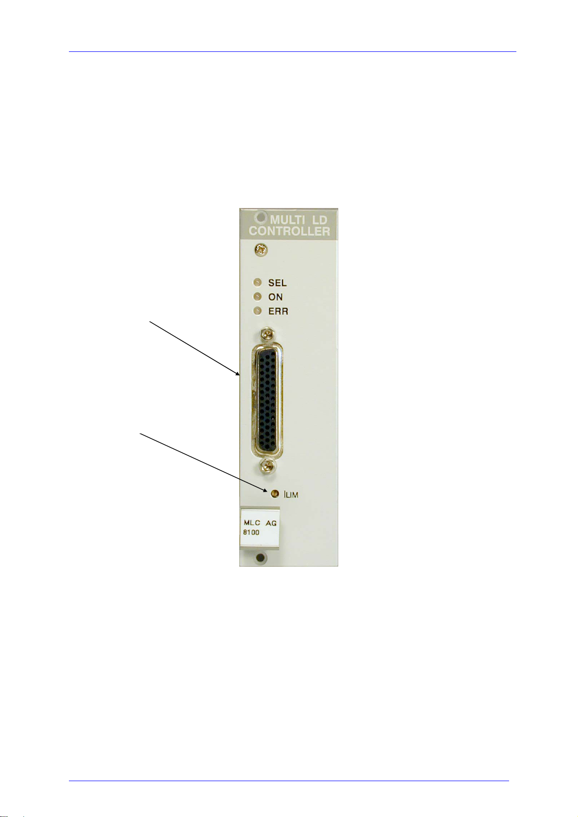
1.5 Operating elements at the front of the module
1.5 Operating elements at the front of the module
Connector for the
laser diodes
Potentiometer for I
LIM
Figure 1 Operating elements on front panel.
MLC8xxx / page 9
Artisan Technology Group - Quality Instrumentation ... Guaranteed | (888) 88-SOURCE | www.artisantg.com
Page 17
1.6 Pre-settings
1.6 Pre-settings
1.6.1 Setting hardware limit I
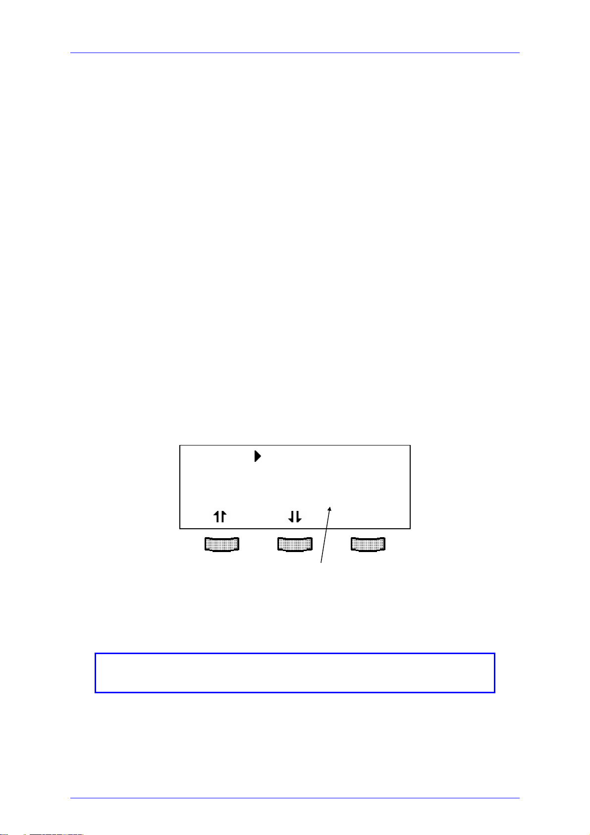
To protect the laser diode the maximum possible current can be limited by hardware
setting.
The setting affects all outputs simultaneously.
The hardware limit I
the module.
(Refer to chapter 1.5, "Operating elements at the front of the module" on page 9)
The value is displayed continually in the channel menu of the module so you can
watch it during adjustment:
is set with the potentiometer marked I
LIM
LIM
at the front panel of
LIM
CH1 I
CC low I
ON I
1= 1.234mA
LS
1=0.1234mA
PA
1=54.321mA
LIM
CHANGE
Hardware limit I
NOTE
I
1 ... I
LIM
8 show the same value not regarding which one is
LIM
used for setting the hardware limit.
LIM
MLC8xxx / page 10
Artisan Technology Group - Quality Instrumentation ... Guaranteed | (888) 88-SOURCE | www.artisantg.com
Page 18
1.7 Connecting components (AG, Anode Ground Version)
1.7 Connecting components (AG, Anode Ground Version)
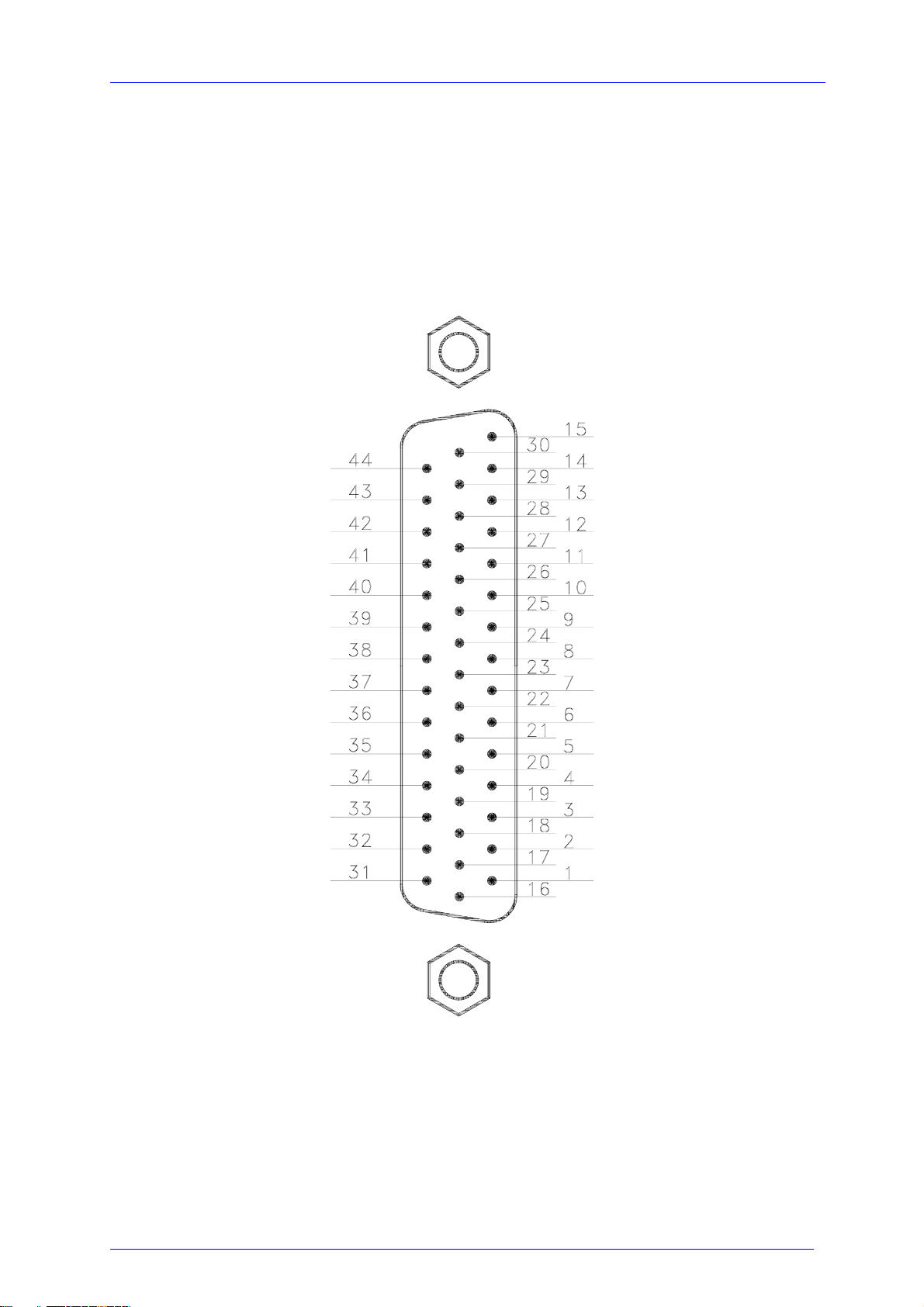
1.7.1 Pinning of the output connector
Figure 2 Pinning of the MLC8xxx output connector
(44-pole female HD-SUB)
MLC8xxx / page 11
Artisan Technology Group - Quality Instrumentation ... Guaranteed | (888) 88-SOURCE | www.artisantg.com
Page 19
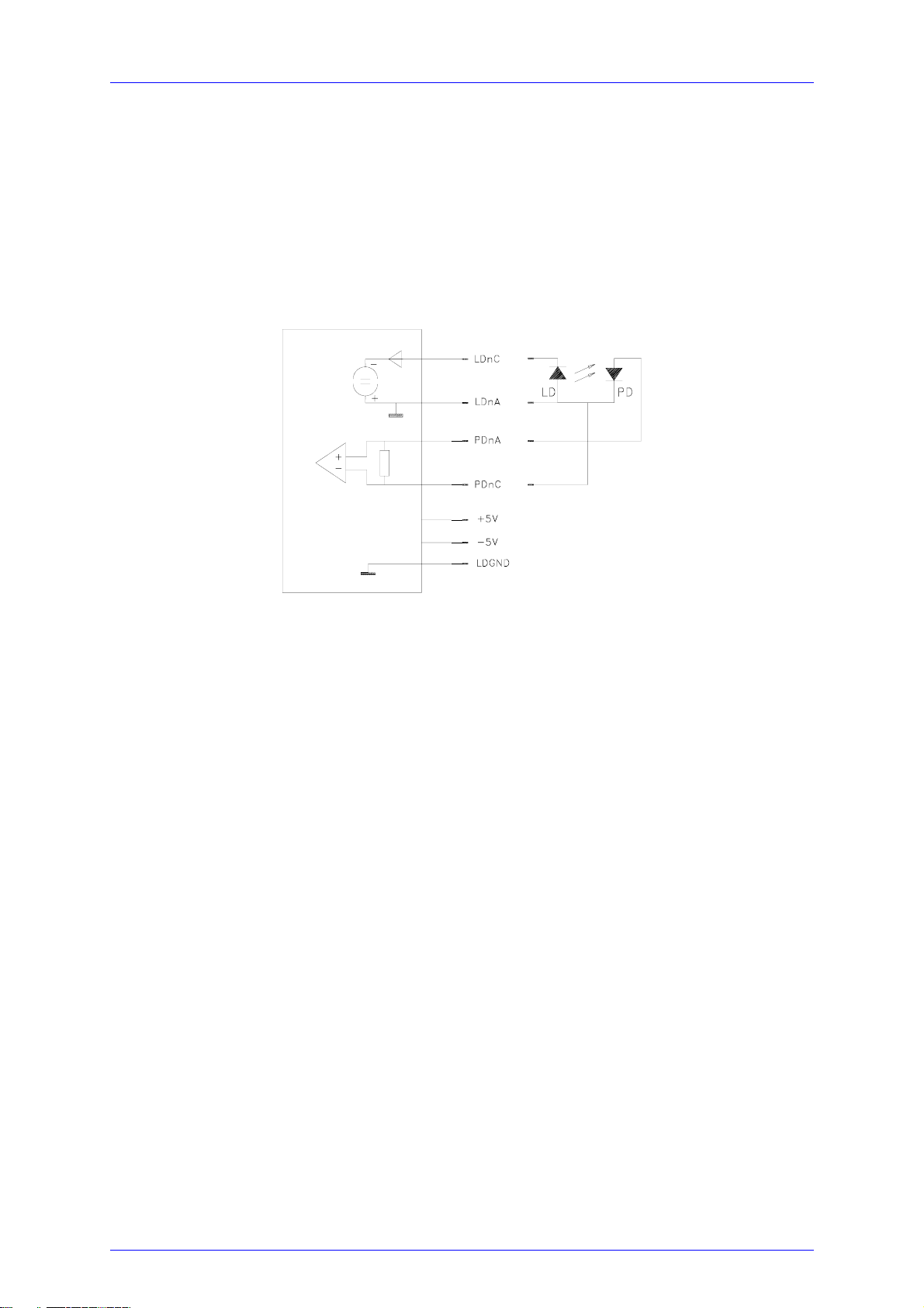
1.7 Connecting components (AG, Anode Ground Version)
1.7.2 Pin assignment MLC8xxx
Each laser is connected to an output channel as shown:
output circuit of the MLC Laser and photo diode
(n = 1 ... 8)
Figure 3 Principle connections for every laser
We recommend to use separate lines drilled in pairs (twisted pair) in a common
shield for laser diode current and monitor diode current respectively.
The shield must be connected to ground!.
MLC8xxx / page 12
Artisan Technology Group - Quality Instrumentation ... Guaranteed | (888) 88-SOURCE | www.artisantg.com
Page 20

1.7 Connecting components (AG, Anode Ground Version)
1.7.2.1 Pin assignment sorted by Function
Pin Connector
14 LD1C cathode of laser # 1
12 LD2C cathode of laser # 2
11 LD3C cathode of laser # 3
9 LD4C cathode of laser # 4
8 LD5C cathode of laser # 5
6 LD6C cathode of laser # 6
5 LD7C cathode of laser # 7
3 LD8C cathode of laser # 8
29 LD1A anode of laser # 1
27 LD2A anode of laser # 2
26 LD3A anode of laser # 3
24 LD4A anode of laser # 4
23 LD5A anode of laser # 5
21 LD6A anode of laser # 6
20 LD7A anode of laser # 7
18 LD8A anode of laser # 8
13 PD1A anode photo diode # 1
42 PD2A anode photo diode # 2
10 PD3A anode photo diode # 3
39 PD4A anode photo diode # 4
7 PD5A anode photo diode # 5
36 PD6A anode photo diode # 6
4 PD7A anode photo diode # 7
33 PD8A anode photo diode # 8
43 PD1C cathode photo diode # 1
41 PD2C cathode photo diode # 2
40 PD3C cathode photo diode # 3
38 PD4C cathode photo diode # 4
37 PD5C cathode photo diode # 5
35 PD6C cathode photo diode # 6
34 PD7C cathode photo diode # 7
32 PD8C cathode photo diode # 8
31 GND ground
16 GND ground
17 GND ground
19 GND ground
22 GND ground
25 GND ground
28 GND ground
MLC8xxx / page 13
Artisan Technology Group - Quality Instrumentation ... Guaranteed | (888) 88-SOURCE | www.artisantg.com
Page 21

1.7 Connecting components (AG, Anode Ground Version)
30 GND ground
44 LEDA out for a LED to show the on/off status
15 Interlock to be shortened to any GND pin
1 + 5V
2 - 5V
MLC8xxx / page 14
Artisan Technology Group - Quality Instrumentation ... Guaranteed | (888) 88-SOURCE | www.artisantg.com
Page 22

1.7 Connecting components (AG, Anode Ground Version)
1.7.2.2 Pin assignment sorted by pin number
Pin Connector
1 + 5V
2 - 5V
3 LD8C cathode of laser # 8
4 PD7A anode photo diode # 7
5 LD7C cathode of laser # 7
6 LD6C cathode of laser # 6
7 PD5A anode photo diode # 5
8 LD5C cathode of laser # 5
9 LD4C cathode of laser # 4
10 PD3A anode photo diode # 3
11 LD3C cathode of laser # 3
12 LD2C cathode of laser # 2
13 PD1A anode photo diode # 1
14 LD1C cathode of laser # 1
15 Interlock to be shortened to any GND pin
16 GND ground
17 GND ground
18 LD8A anode of laser # 8
19 GND ground
20 LD7A anode of laser # 7
21 LD6A anode of laser # 6
22 GND ground
23 LD5A anode of laser # 5
24 LD4A anode of laser # 4
25 GND ground
26 LD3A anode of laser # 3
27 LD2A anode of laser # 2
28 GND ground
29 LD1A anode of laser # 1
30 GND ground
31 GND ground
32 PD8C cathode photo diode # 8
33 PD8A anode photo diode # 8
34 PD7C cathode photo diode # 7
35 PD6C cathode photo diode # 6
36 PD6A anode photo diode # 6
37 PD5C cathode photo diode # 5
38 PD4C cathode photo diode # 4
39 PD4A anode photo diode # 4
MLC8xxx / page 15
Artisan Technology Group - Quality Instrumentation ... Guaranteed | (888) 88-SOURCE | www.artisantg.com
Page 23

1.7 Connecting components (AG, Anode Ground Version)
40 PD3C cathode photo diode # 3
41 PD2C cathode photo diode # 2
42 PD2A anode photo diode # 2
43 PD1C cathode photo diode # 1
44 LEDA out for a LED to show the on/off status
MLC8xxx / page 16
Artisan Technology Group - Quality Instrumentation ... Guaranteed | (888) 88-SOURCE | www.artisantg.com
Page 24

1.7 Connecting components (AG, Anode Ground Version)
1.7.3 Connecting laser- and monitor diode
Laser diodes are produced in many different housings. Normally the following
components are installed together in the chassis of the laser:
• Laser diode
• Monitor diode
• TEC element for setting the chip temperature
• Temperature sensor
The laser diode is always sourced against ground by the current controller. This is of
considerable advantage regarding the safety of the laser diode and the stability of the
laser diode current.
The monitor diode input is set up as trans-impedance amplifier with virtual ground
(input impedance 0Ω).
The polarity of the photo diode may be selected free. It can also be floating.
The monitor diode input can be used with or without bias voltage (5 V or 0 V).
Therefore wire bridges have to be connected depending on the individual
configuration shown in the next section.
MLC8xxx / page 17
Artisan Technology Group - Quality Instrumentation ... Guaranteed | (888) 88-SOURCE | www.artisantg.com
Page 25
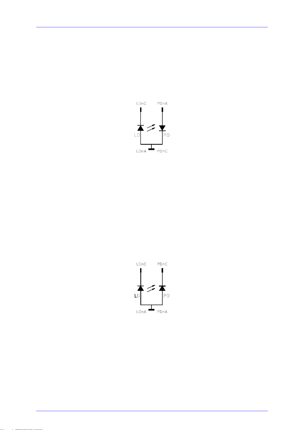
1.7 Connecting components (AG, Anode Ground Version)
1.7.4 Standard configurations, no bias voltage
1.7.4.1 Laser anode on ground / photo diode cathode on ground
n = number of channel (1 to 8)
Figure 4 Laser AG / photo diode CG, no bias
1.7.4.2 Laser anode on ground / photo diode anode on ground
n = number of channel (1 to 8)
Figure 5 Laser AG / photo diode AG, no bias
MLC8xxx / page 18
Artisan Technology Group - Quality Instrumentation ... Guaranteed | (888) 88-SOURCE | www.artisantg.com
Page 26
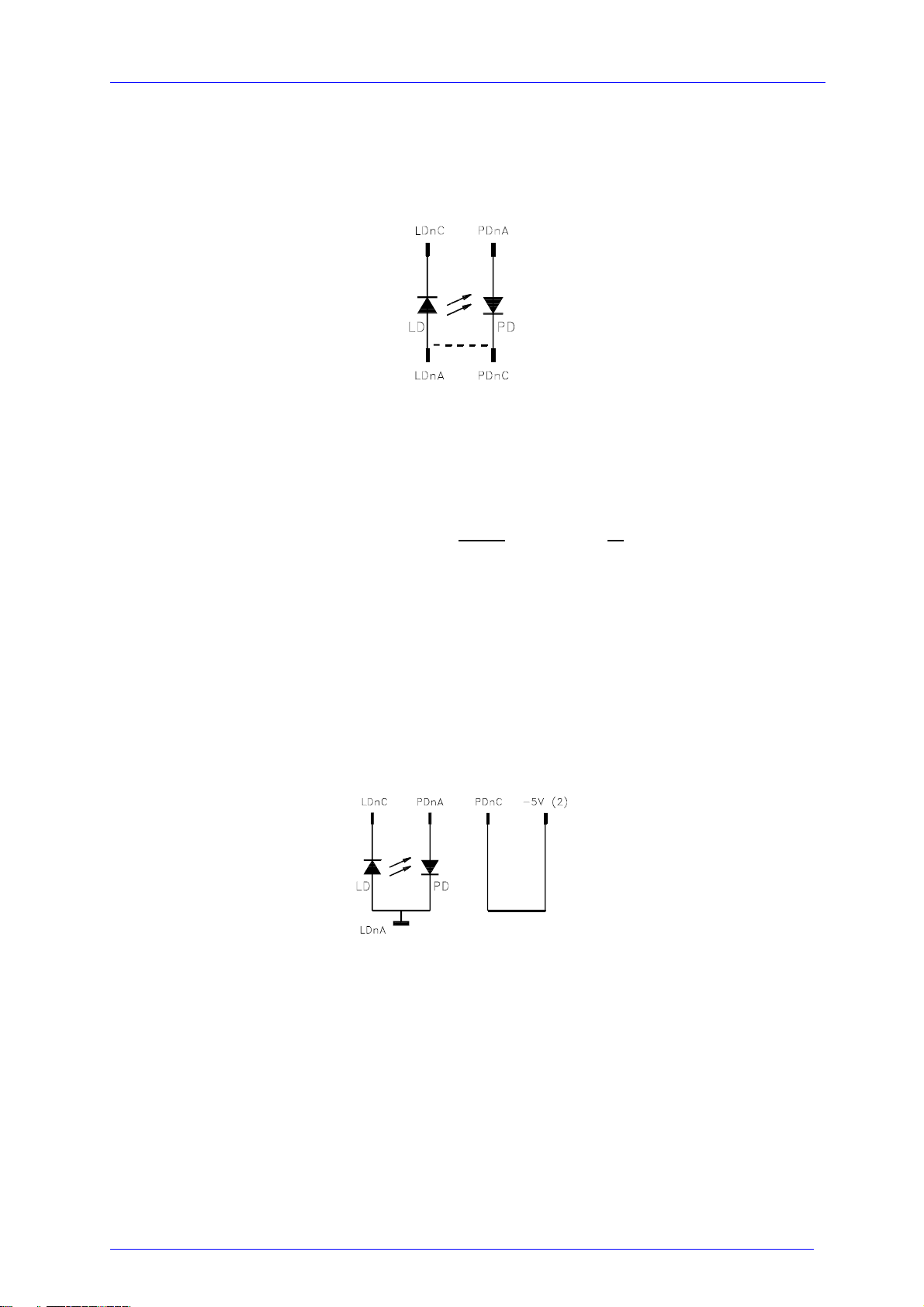
1.7 Connecting components (AG, Anode Ground Version)
1.7.4.3 Laser anode on ground / photo diode floating
n = number of channel (1 to 8)
Figure 6 Laser AG / photo diode floating, no bias
a bridge (dashed line) may be used either at the laser or at the connector
1.7.5 Standard configurations with bias voltage 5V
1.7.5.1 Laser anode on ground / photo diode cathode on ground
n = number of channel (1 to 8)
Figure 7 Laser AG / photo diode CG, 5V bias
MLC8xxx / page 19
Artisan Technology Group - Quality Instrumentation ... Guaranteed | (888) 88-SOURCE | www.artisantg.com
Page 27
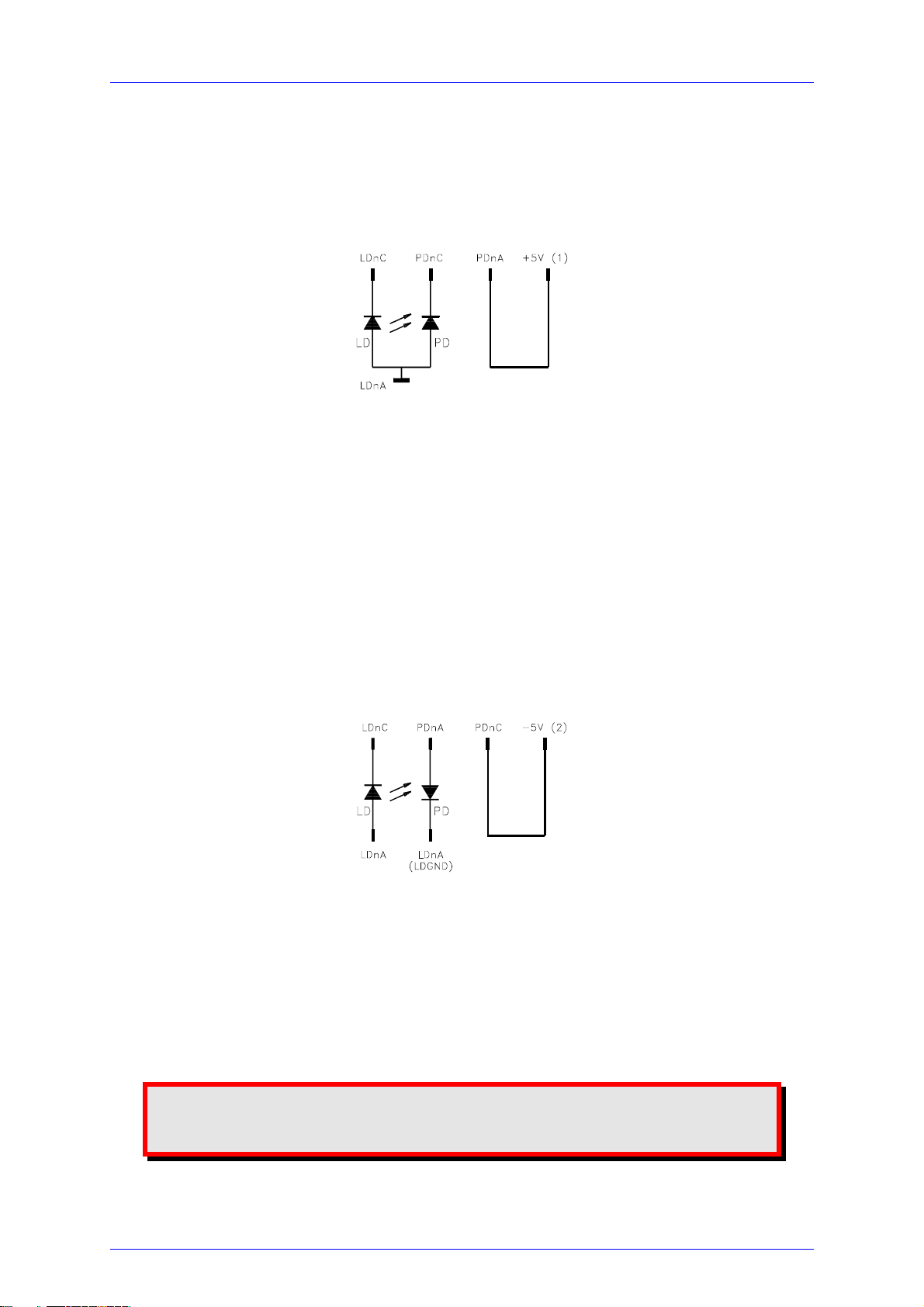
1.7 Connecting components (AG, Anode Ground Version)
1.7.5.2 Laser anode on ground / photo diode anode on ground
n = number of channel (1 to 8)
Figure 8 Laser AG / photo diode AG, 5V bias
1.7.5.3 Laser anode on ground / photo diode floating
n = number of channel (1 to 8)
Figure 9 Laser AG / photo diode floating, 5V bias
Attention
Reverse connection of the photo diode using a bias voltage can
cause permanent damage to the device.
MLC8xxx / page 20
Artisan Technology Group - Quality Instrumentation ... Guaranteed | (888) 88-SOURCE | www.artisantg.com
Page 28

1.7 Connecting components (AG, Anode Ground Version)
1.7.6 Connecting interlock and status display
Interlock, cable damage monitoring
Pin 15 connected to any GND pin of the connector jack will serve as test connector to
determine whether the current output for the laser diode may be switched on.
Between the two pins a low resistive (< 430Ω) connection must be maintained. Also
short-circuiting is permitted. With the contacts open the multi laser controller module
cannot be switched on.
Should the contact open during operation the output will be switched off immediately.
Status display
It is also possible to use a LED with anode to pin 44 and cathode to any GND pin as
status display.
The LED will light up if the current output is switched on.
MLC8xxx / page 21
Artisan Technology Group - Quality Instrumentation ... Guaranteed | (888) 88-SOURCE | www.artisantg.com
Page 29
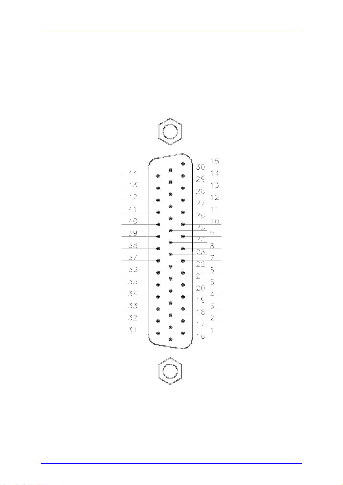
1.8 Connecting components (CG, Cathode Ground Version)
1.8 Connecting components (CG, Cathode Ground Version)
1.8.1 Pinning of the output connector
Figure 10 Pinning of the MLC8xxx output connector
(44-pole female HD-SUB-D)
MLC8xxx / page 22
Artisan Technology Group - Quality Instrumentation ... Guaranteed | (888) 88-SOURCE | www.artisantg.com
Page 30
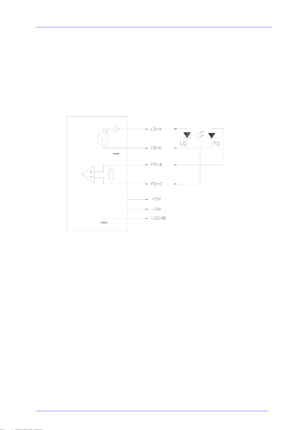
1.8 Connecting components (CG, Cathode Ground Version)
1.8.2 Pin assignment MLC8xxx
Each laser is connected to an output channel as shown:
output circuit of the MLC Laser and photo diode
(n = 1 ... 8)
Figure 11 Principle connections for every laser
We recommend to use separate lines drilled in pairs (twisted pair) in a common
shield for laser diode current and monitor diode current respectively.
The shield must be connected to ground.
MLC8xxx / page 23
Artisan Technology Group - Quality Instrumentation ... Guaranteed | (888) 88-SOURCE | www.artisantg.com
Page 31

1.8 Connecting components (CG, Cathode Ground Version)
1.8.2.1 Pin assignment sorted by Function
Pin Connector
14 LD1A anode of laser # 1
12 LD2A anode of laser # 2
11 LD3A anode of laser # 3
9 LD4A anode of laser # 4
8 LD5A anode of laser # 5
6 LD6A anode of laser # 6
5 LD7A anode of laser # 7
3 LD8A anode of laser # 8
29 LD1C cathode of laser # 1
27 LD2C cathode of laser # 2
26 LD3C cathode of laser # 3
24 LD4C cathode of laser # 4
23 LD5C cathode of laser # 5
21 LD6C cathode of laser # 6
20 LD7C cathode of laser # 7
18 LD8C cathode of laser # 8
13 PD1A anode of the photo diode of laser # 1
42 PD2A anode of the photo diode of laser # 2
10 PD3A anode of the photo diode of laser # 3
39 PD4A anode of the photo diode of laser # 4
7 PD5A anode of the photo diode of laser # 5
36 PD6A anode of the photo diode of laser # 6
4 PD7A anode of the photo diode of laser # 7
33 PD8A anode of the photo diode of laser # 8
43 PD1C cathode of the photo diode of laser # 1
41 PD2C cathode of the photo diode of laser # 2
40 PD3C cathode of the photo diode of laser # 3
38 PD4C cathode of the photo diode of laser # 4
37 PD5C cathode of the photo diode of laser # 5
35 PD6C cathode of the photo diode of laser # 6
34 PD7C cathode of the photo diode of laser # 7
32 PD8C cathode of the photo diode of laser # 8
31 GND ground
16 GND ground
17 GND ground
19 GND ground
22 GND ground
25 GND ground
28 GND ground
MLC8xxx / page 24
Artisan Technology Group - Quality Instrumentation ... Guaranteed | (888) 88-SOURCE | www.artisantg.com
Page 32

1.8 Connecting components (CG, Cathode Ground Version)
30 GND ground
44 LEDA out for a LED to show the on/off status
15 Interlock to be shortened to any GND pin
1 + 5V
2 - 5V
MLC8xxx / page 25
Artisan Technology Group - Quality Instrumentation ... Guaranteed | (888) 88-SOURCE | www.artisantg.com
Page 33

1.8 Connecting components (CG, Cathode Ground Version)
1.8.2.2 Pin assignment sorted by number of pin
Pin Connector
1 + 5V
2 - 5V
3 LD8A anode laser # 8
4 PD7A anode photo diode # 7
5 LD7A anode laser # 7
6 LD6A anode laser # 6
7 PD5A anode photo diode # 5
8 LD5A anode laser # 5
9 LD4A anode laser # 4
10 PD3A anode photo diode # 3
11 LD3A anode laser # 3
12 LD2A anode laser # 2
13 PD1A anode photo diode # 1
14 LD1A anode of laser # 1
15 Interlock to be shortened to any GND pin
16 GND ground
17 GND ground
18 LD8C cathode laser # 8
19 GND ground
20 LD7C cathode laser # 7
21 LD6C cathode laser # 6
22 GND ground
23 LD5C cathode laser # 5
24 LD4C cathode laser # 4
25 GND ground
26 LD3C cathode laser # 3
27 LD2C cathode laser # 2
28 GND ground
29 LD1C cathode laser # 1
30 GND ground
31 GND ground
32 PD8C cathode photo diode # 8
33 PD8A anode photo diode # 8
34 PD7C cathode photo diode # 7
35 PD6C cathode photo diode # 6
36 PD6A anode photo diode # 6
37 PD5C cathode photo diode # 5
38 PD4C cathode photo diode # 4
39 PD4A anode photo diode # 4
MLC8xxx / page 26
Artisan Technology Group - Quality Instrumentation ... Guaranteed | (888) 88-SOURCE | www.artisantg.com
Page 34

1.8 Connecting components (CG, Cathode Ground Version)
40 PD3C cathode photo diode # 3
41 PD2C cathode photo diode # 2
42 PD2A anode photo diode # 2
43 PD1C cathode photo diode # 1
44 LEDA out for a LED to show the on/off status
MLC8xxx / page 27
Artisan Technology Group - Quality Instrumentation ... Guaranteed | (888) 88-SOURCE | www.artisantg.com
Page 35

1.8 Connecting components (CG, Cathode Ground Version)
1.8.3 Connecting laser- and monitor diode
Laser diodes are produced in many different housings. Normally the following
components are installed together in the chassis of the laser:
• Laser diode
• Monitor diode
• TEC element for setting the chip temperature
• Temperature sensor
The laser diode is always sourced against ground by the current controller. This is of
considerable advantage regarding the safety of the laser diode and the stability of the
laser diode current.
The monitor diode input is set up as trans-impedance amplifier with virtual ground
(input impedance 0 Ω).
The polarity of the photo diode may be selected free. It can also be floating.
The monitor diode input can be used with or without bias voltage (5 V or 0 V).
Therefore wire bridges have to be connected depending on the individual
configuration shown in the next section.
MLC8xxx / page 28
Artisan Technology Group - Quality Instrumentation ... Guaranteed | (888) 88-SOURCE | www.artisantg.com
Page 36
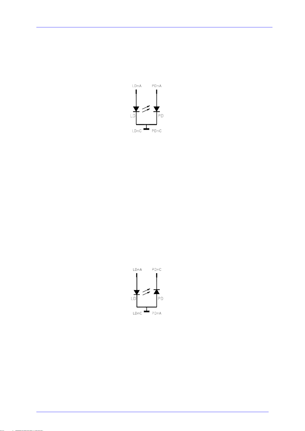
1.8 Connecting components (CG, Cathode Ground Version)
1.8.4 Standard configurations without bias voltage
1.8.4.1 Laser cathode on ground / photo diode cathode on ground
n = number of channel (1 to 8)
Figure 12 Laser CG / photo diode CG, no bias
1.8.4.2 Laser cathode on ground / photo diode anode on ground
n = number of channel (1 to 8)
Figure 13 Laser CG / photo diode AG, no bias
MLC8xxx / page 29
Artisan Technology Group - Quality Instrumentation ... Guaranteed | (888) 88-SOURCE | www.artisantg.com
Page 37
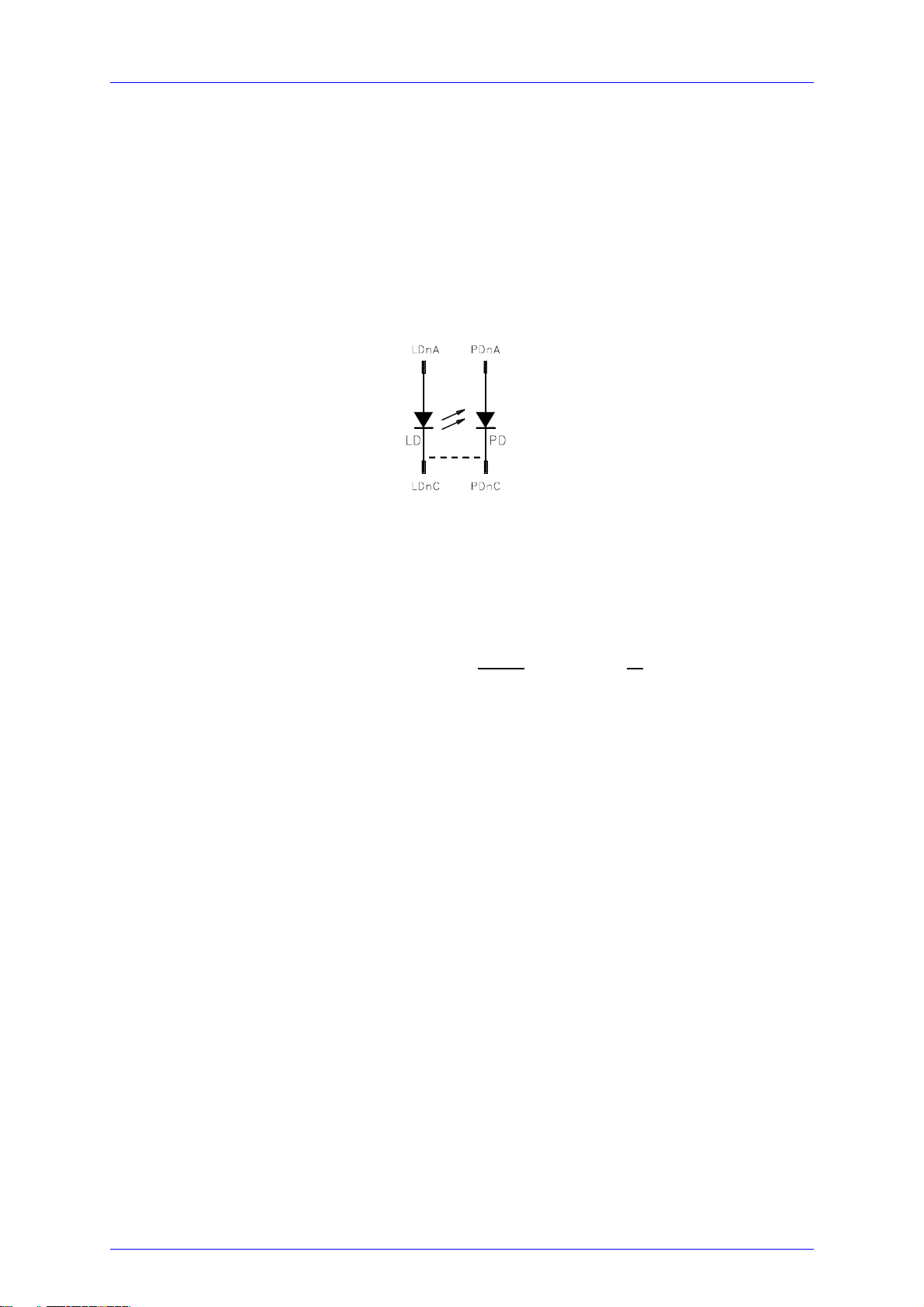
1.8 Connecting components (CG, Cathode Ground Version)
1.8.4.3 Laser cathode on ground / photo diode floating
n = number of channel (1 to 8)
Figure 14 Laser CG / photo diode floating, no bias
a connection (dashed line) may be done either at the laser or at the connector
MLC8xxx / page 30
Artisan Technology Group - Quality Instrumentation ... Guaranteed | (888) 88-SOURCE | www.artisantg.com
Page 38
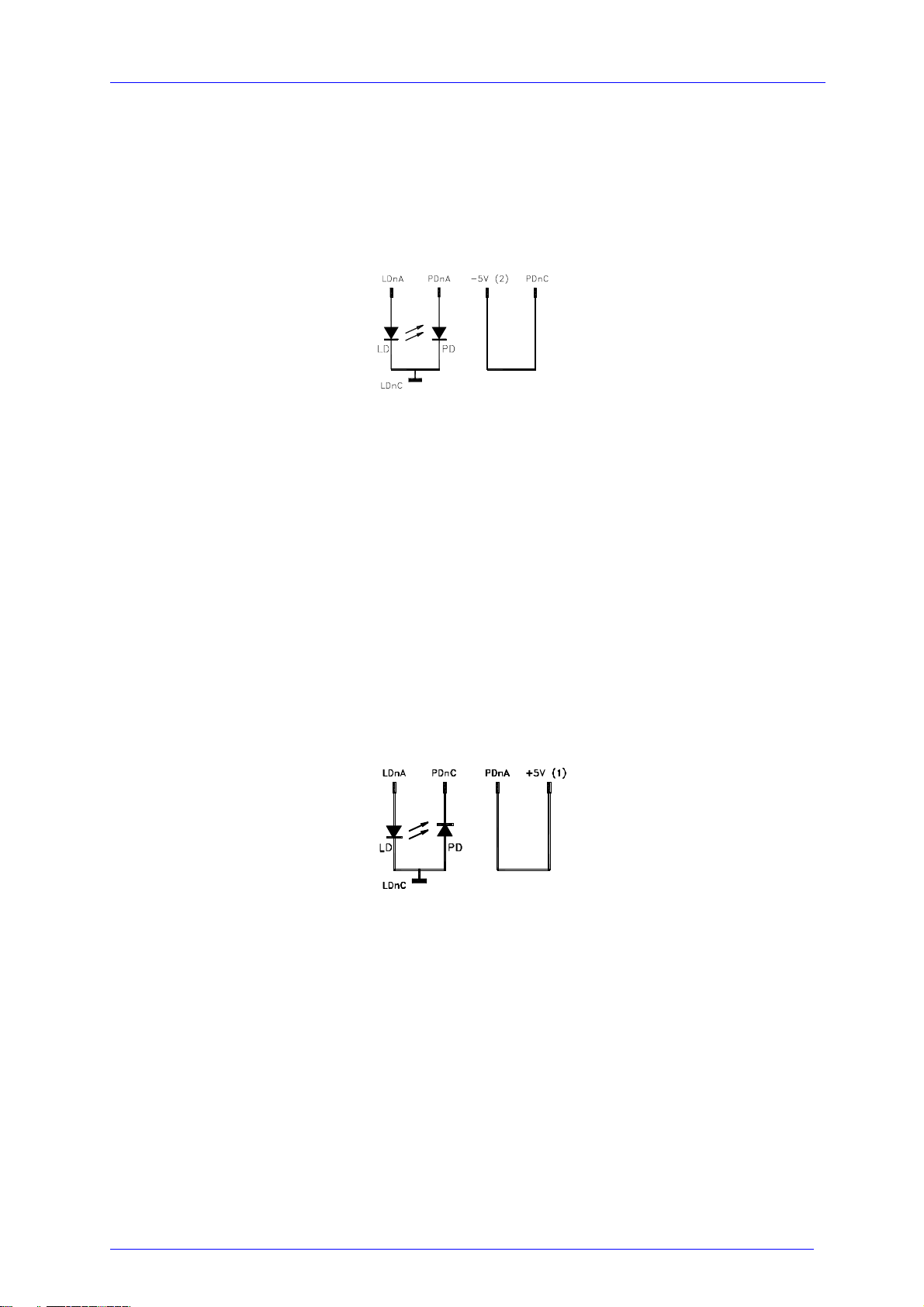
1.8 Connecting components (CG, Cathode Ground Version)
1.8.5 Standard configurations with bias voltage 5V
1.8.5.1 Laser cathode on ground / photo diode cathode on ground
n = number of channel (1 to 8)
Figure 15 Laser CG / photo diode CG, with 5 V bias
1.8.5.2 Laser cathode on ground / photo diode anode on ground
n = number of channel (1 to 8)
Figure 16 Laser CG / photo diode AG
MLC8xxx / page 31
Artisan Technology Group - Quality Instrumentation ... Guaranteed | (888) 88-SOURCE | www.artisantg.com
Page 39
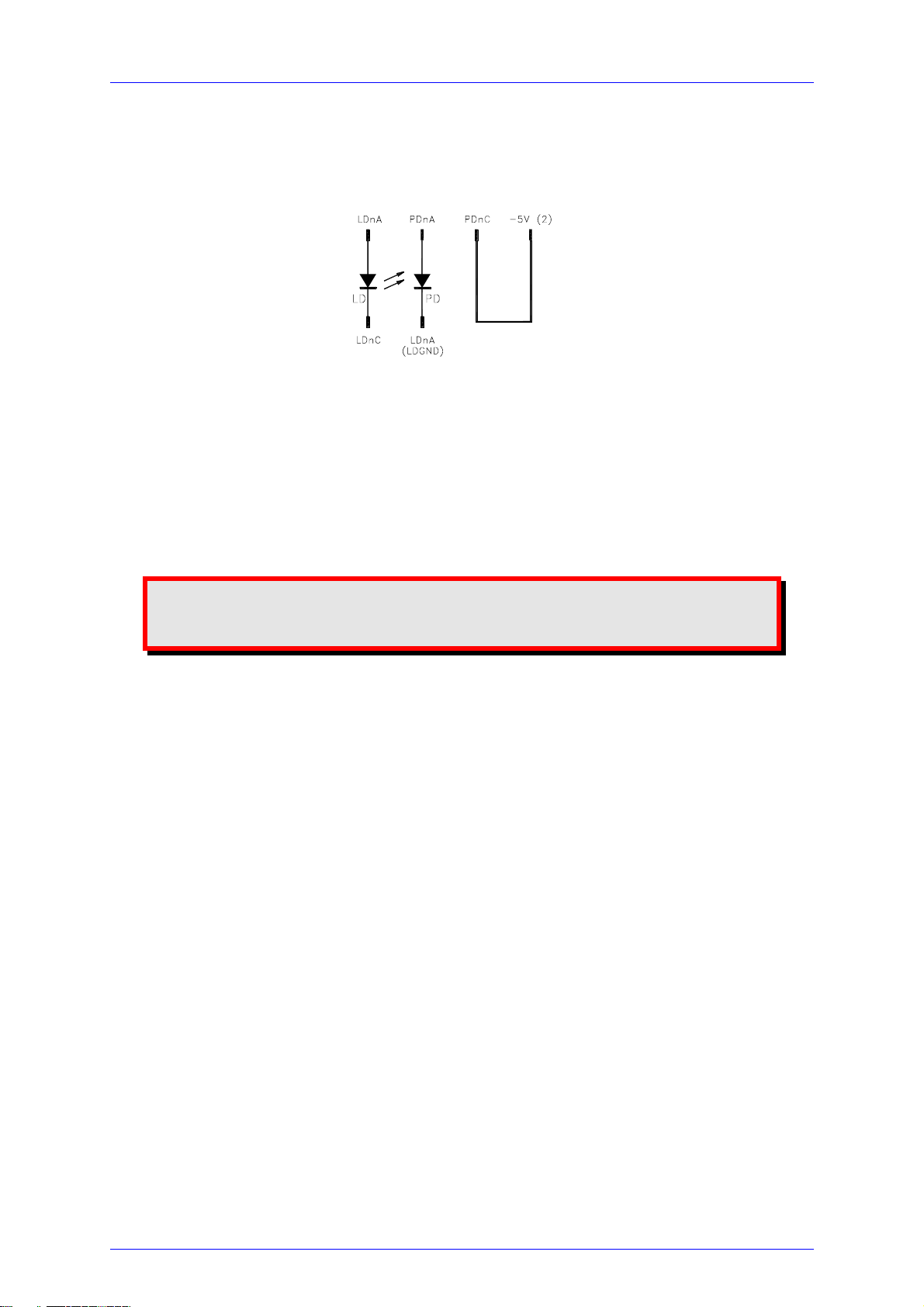
1.8 Connecting components (CG, Cathode Ground Version)
1.8.5.3 Laser cathode on ground / photo diode floating
n = number of channel (1 to 8)
Figure 17 Laser CG / photo diode floating, 5 V bias
Attention
Reverse connection of the photo diode can cause permanent damage
to the device when using a bias voltage!
1.8.6 Connecting interlock and status display
Interlock, cable damage monitoring
Pin 15 connected to any GND pin of the connector jack will serve as test connector to
determine whether the current output for the laser diode may be switched on.
Between the two pins a low resistance (<430 Ω) must be maintained. Also short-
circuiting is permitted. With the contacts open the multi laser controller module
cannot be switched on.
Should the contact open during operation the output is switched off immediately.
Status display
It is also possible to use a LED with anode to pin 44 and cathode to any GND pin as
status monitor.
The LED will light up if the current output is switched on.
MLC8xxx / page 32
Artisan Technology Group - Quality Instrumentation ... Guaranteed | (888) 88-SOURCE | www.artisantg.com
Page 40
2.1 Functions in the main menu
2 Operating the MLC8xxx
Before switching on the laser current please refer to chapter 1.6, "Pre-settings"
starting on page 10
NOTE
With modules of the MLC8xxx series all settings are executed at once. It is
not necessary to confirm the set values.
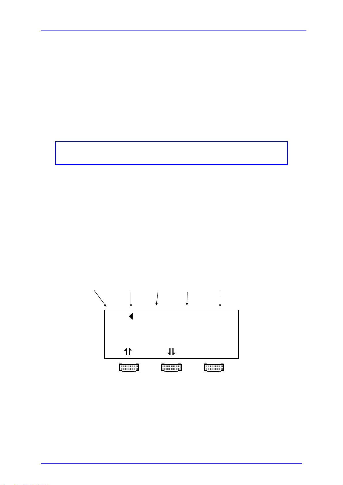
2.1 Functions in the main menu
2.1.1 Display
The main menu shows the channel number, mode, range and status of the MLC8xxx
module.
channel no. Cursor mode range status
CH1 Iconst low off
CH2 Iconst low off
CH3 Iconst low off
TUNE
MLC8xxx / page 33
Artisan Technology Group - Quality Instrumentation ... Guaranteed | (888) 88-SOURCE | www.artisantg.com
Page 41

2.1 Functions in the main menu
2.1.2 Selecting a module
Select a module for further input by setting the cursor to the channel number of the
desired module using the softkeys and .
CH2
Pressing will lead to the channel menu
(Refer to chapter 2.2, "Functions in the channel menu" starting on page 35)
MLC8xxx / page 34
Artisan Technology Group - Quality Instrumentation ... Guaranteed | (888) 88-SOURCE | www.artisantg.com
Page 42
2.2 Functions in the channel menu
2.2 Functions in the channel menu
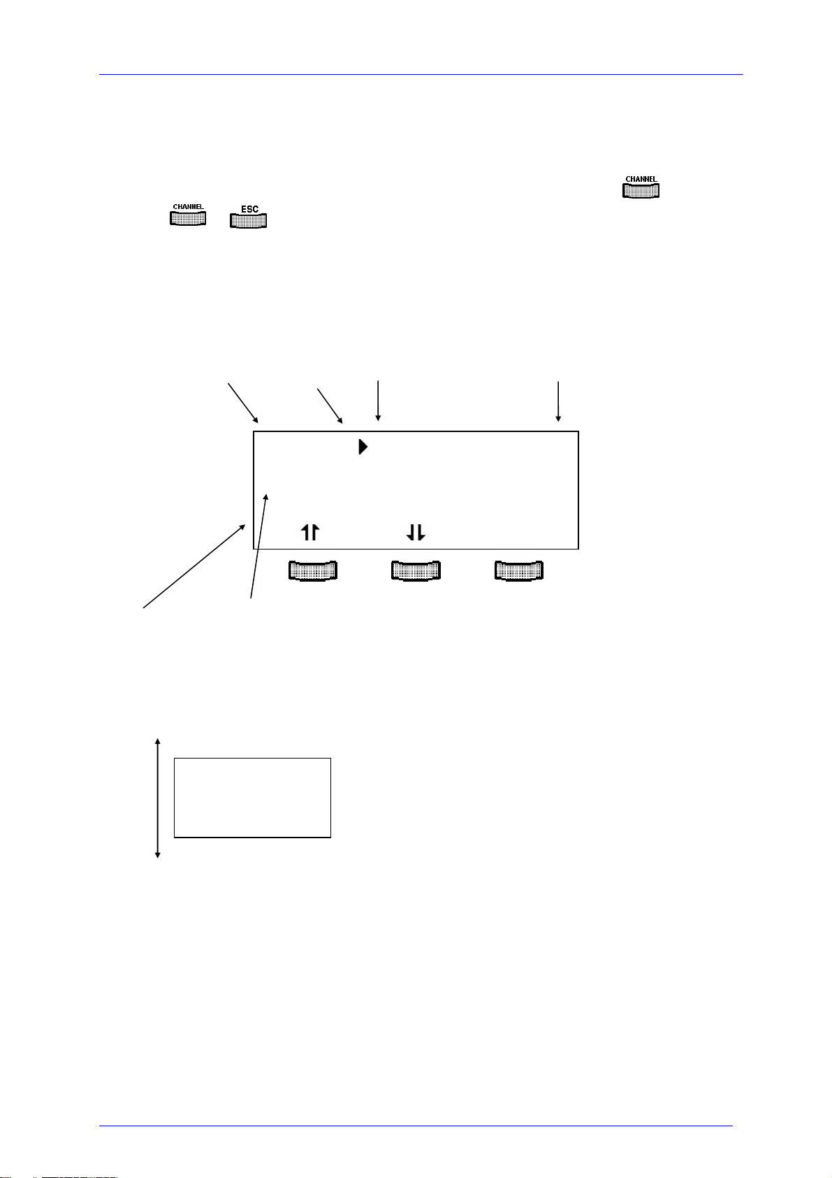
The channel menu is opened from the main menu by pressing the key .
Hit again or
to return to the main menu.
2.2.1 Display
In the channel menu all parameters of the selected module are shown:
channel no. cursor operating parameters
CH3 RANGE = LOW
CC low MODE = Iconst
OFF Twin OFF
CHANGE
status field operating mode
Only three parameters can be shown at a time, so there is a scroll function. All
parameters are sorted in a virtual list, which can be run through with the cursor:
RANGE = LOW
MODE = Iconst
Twin OFF
Twin slot= -
I
1=19.000mA
LS
I
1=0.0022mA
PA
I
1=59.000mA
LIM
.
.
.
I
8=19.000mA
LS
I
8=0.0022mA
PA
I
8=59.000mA
LIM
MLC8xxx / page 35
Artisan Technology Group - Quality Instrumentation ... Guaranteed | (888) 88-SOURCE | www.artisantg.com
Page 43

2.2 Functions in the channel menu
The status field shows the actual status:
Normal operation
ON Laser is on
OFF Laser is off
Malfunction
Vcc Internal power supply failed – maintenance required
OTP Final stage overheated – switch off and wait 10 minutes
ILCK Interlock is open
ILIM Limit current reached during operation
In the channel menu you find some abbreviations which are explained as follows
In constant current mode:
ILS 1 ... ILS 8 Laser diode set current of channel 1... 8
IPA 1 ... IPA 1 Photo diode actual current of channel 1 ... 8
In constant power mode:
IPS 1 ... IPS 8 Photo diode set current of channel 1 ... 8
ILA 1 ... ILA 8 Laser diode actual current of channel 1 ... 8
In both modes
I
LIM
1 ... I
8 Limit current (is the same for chanell 1 ... 8)
LIM
MLC8xxx / page 36
Artisan Technology Group - Quality Instrumentation ... Guaranteed | (888) 88-SOURCE | www.artisantg.com
Page 44
2.2 Functions in the channel menu
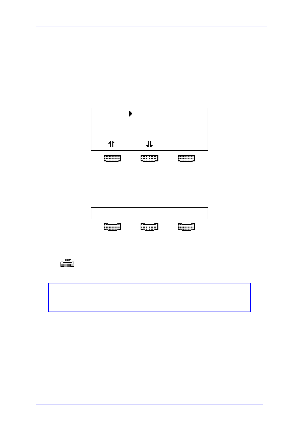
2.2.2 Changing parameters
To set or change a numerical parameter in the channel menu select the respective
line with the cursor:
Example: change ILS 1:
CH1 I
CC low I
OFF I
1=21.234mA
LS
1=0.0019mA
PA
1=49.000mA
LIM
CHANGE
Pressing the key (CHANGE), will activate the tuning knob to change the selected
parameter. If the parameter is only to toggle (e.g. the polarity of the laser diode) the
function of the softkeys will change:
TOGGLE:const CUR/POW
Pressing the right softkey toggles the mode.
Pressing
Some parameters can not be changed, as they are measurement values
(i.e. the laser voltage) or may not be changed with the laser switched on.
MLC8xxx / page 37
will terminate the procedure.
NOTE
In these cases access is denied indicated by a long beep.
Artisan Technology Group - Quality Instrumentation ... Guaranteed | (888) 88-SOURCE | www.artisantg.com
Page 45

2.2 Functions in the channel menu
2.2.3 Selecting the laser diode current range
If the range of the laser diode current shall be changed, the parameter
RANGE =
has to be selected in the channel menu.
The right softkey will toggle between “high” and “low” range.
2.2.4 Selecting constant current or constant power mode
The multi laser controller modules MLC8xxx offer two operating modes for the laser
diodes: constant current and constant power mode.
In constant current mode the laser diode current will be kept constant. If the
temperature of the laser changes the optical power will change too, since the laser
efficiency will change.
In the channel menu you can select the mode Iconst.
If the set-up uses a monitor diode receiving a certain part of the laser light the
measured monitor diode current can be kept constant by adjusting the laser diode
current correspondingly. Changes in temperature of the laser will cause a change of
its efficiency but the laser diode current is re-set for the optical power to remain
constant. This is called constant power mode, Pconst
.
NOTE
For "constant power" mode a separate monitor diode will be necessary for
each laser in the set-up.
MLC8xxx / page 38
Artisan Technology Group - Quality Instrumentation ... Guaranteed | (888) 88-SOURCE | www.artisantg.com
Page 46

2.2 Functions in the channel menu
So if the operating mode of the laser diodes shall be changed, the parameter
MODE =
can be set to:
Iconst = Constant current mode
Pconst = Constant power mode
(Refer to chapter 2.2.2, "Changing parameters" on page 37)
MLC8xxx / page 39
Artisan Technology Group - Quality Instrumentation ... Guaranteed | (888) 88-SOURCE | www.artisantg.com
Page 47

2.2 Functions in the channel menu
2.2.5 Selecting a TEC module for temperature protection
If the laser diodes should be operated only in a specific temperature range (window)
you can use the temperature window function of a TED 8xxx module.
(Refer to manual of the TED8xxx)
The TED8xxx must be assigned to the MLC8xxx as described here. Two steps are
necessary:
First the parameter
Twin slot =
must be set to the slot number of the desired TED8xxx.
(If only one TED8xxx is inserted, the slot number is recognized automatically)
2.2.6 Activating the temperature protection
Second the temperature protection must be switched ON:
Twin ON
If the temperature protection shall not be active it has to be switched off again:
Twin OFF
MLC8xxx / page 40
Artisan Technology Group - Quality Instrumentation ... Guaranteed | (888) 88-SOURCE | www.artisantg.com
Page 48
2.3 Switching on and off
2.3 Switching on and off
Attention
MLC8xxx modules can be switched on or off not regarding if any
parameters have been set.
Please select the module to be switched on or off in the main menu.
(Refer to chapter 2.1.2, "Selecting a module" on page 34)
Attention
Before switching on a multi laser diode controller module MLC8xxx
first set the laser diode current limit I
applied laser diodes with a screwdriver.
The corresponding potentiometer is marked I
front panel of the current module.
(Refer to chapter 1.6.1, "Setting hardware limit I
Pressing the key
as long as the module is selected (LED “SEL” lights). The LED “ON” at the respective
module will light up.
will switch on the module not regarding the menu you are in
(hardware limit) for the
LIM
and is situated at the
LIM
” on page 10
LIM
MLC8xxx / page 41
Artisan Technology Group - Quality Instrumentation ... Guaranteed | (888) 88-SOURCE | www.artisantg.com
Page 49
2.4 Error messages
2.4 Error messages
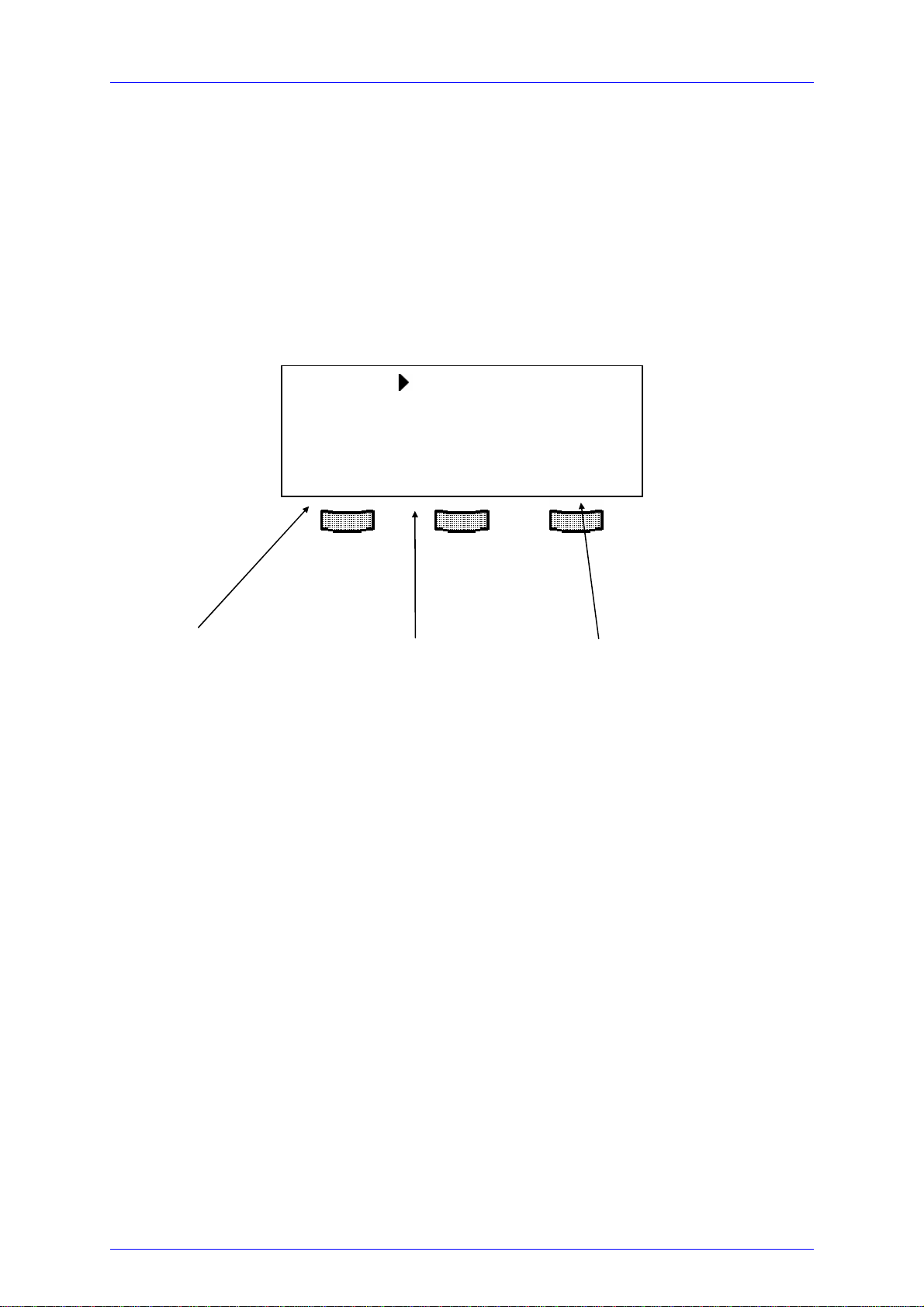
Error messages are shown in the bottom line of the display not regarding, if you are
in the main menu or channel menu.
If an error occurs with the module switched on the display shows for example:
CH1 I
CC low I
OFF I
1=21.234mA
LS
1=0.0019mA
PA
1=49.000mA
LIM
<CH3 interlock> ok
Channel causing the error Error message ok to accept
Possible error messages for an MLC8xxx module are:
INTERLOCK Interlock line is open or has opened
ctrl Temp Laser temperature left temperature window
OTP Module is overheated. Operation is possible after cooling
down.
Vcc fail Internal supply voltage fails - module needs maintenance.
Not if LD on Certain parameters are not allowed to be changed while
laser is ON.
TWIN Laser temperature left temperature window.
If the error occurs during operation it is written in brackets:
<CH1 INTERLOCK>
MLC8xxx / page 42
Artisan Technology Group - Quality Instrumentation ... Guaranteed | (888) 88-SOURCE | www.artisantg.com
Page 50

2.4 Error messages
If the error occurs by trying to switch on it is written in cursor arrows:
CH1 interlock
If an error occurs, it has to be acknowledged by pressing "ok" . Until acknowl-
edgement further operation is locked.
MLC8xxx / page 43
Artisan Technology Group - Quality Instrumentation ... Guaranteed | (888) 88-SOURCE | www.artisantg.com
Page 51

3.1 General notes on remote control
3 Communicating with a control computer
3.1 General notes on remote control
The description of the mainframe of the PRO8000 (-4) / PRO800 includes all
instructions of how to prepare and execute the programming of the system via a
computer interface.
Special operation features of the MLC8xxx module are described here.
(Refer to chapter 2, "Operating the MLC8xxx" starting on page 33)
NOTE
All analog values are read and written in SI units, i.e. A (not mA), W (not
mW) etc. Letters may be written in small or capital letters.
Attention
Before programming a multi laser diode controller module first set
the limit value of the laser diode current I
applied laser diodes with a screwdriver.
The corresponding potentiometer is marked I
front panel of the MLC8xxx module.
The value I
and can be checked in the channel -menu of the MLC8xxx during
is constantly measured by the PRO8000 (-4) / PRO800
LIM
(hardware limit) for the
LIM
and is situated at the
LIM
setting.
(Refer to chapter 1.6.1, "Setting hardware limit I
MLC8xxx / page 44
Artisan Technology Group - Quality Instrumentation ... Guaranteed | (888) 88-SOURCE | www.artisantg.com
" on page10)
LIM
Page 52

3.1 General notes on remote control
3.1.1 Nomenclature
Program messages (PC ⇒ PRO8000) are written in inverted commas: "*IDN?"
Response messages (PRO8000 ⇒ PC) are written in brackets: [:SLOT 1]
There is a decimal point: 1.234
Parameters are separated with comma: "PLOT 2,0"
Commands are separated with semicolon: "*IDN?;*STB?"
3.1.2 Data format
According to the IEEE 488.2 specifications all data variables are divided into 4
different data formats:
Character response data (<CRD>)
Is a single character or a string. Examples:
A or ABGRS or A125TG or A1.23456A
(Refer to IEE488.2 (8.7.1))
Numeric response data Type 1 (<NR1>)
Is a numerical value with sign in integer notation. Examples:
1 or +1 or -22 or 14356789432
(Refer to IEE488.2 (8.7.2))
MLC8xxx / page 45
Artisan Technology Group - Quality Instrumentation ... Guaranteed | (888) 88-SOURCE | www.artisantg.com
Page 53

3.1 General notes on remote control
Numeric response data Type 2 (<NR2>)
Is a numerical value with or without sign in floating point notation without exponent.
Examples:
1.1 or +1.1 or -22.1 or 14356.789432
(Refer to IEE488.2 (8.7.3))
Numeric response data Type 3 (<NR3>)
Is a numerical value with or without sign in floating point notation with exponent with
sign . Examples:
1.1E+1 or +1.1E-1 or -22.1E+1 or 143.56789432E+306
(Refer to IEE488.2 (8.7.4))
MLC8xxx / page 46
Artisan Technology Group - Quality Instrumentation ... Guaranteed | (888) 88-SOURCE | www.artisantg.com
Page 54

3.2 Commands
3.2 Commands
3.2.1 Select the module slot
":SLOT <NR1>" Selects a slot for further programming
<Nr1>=1…8 (PRO8000(-4)), 1…2 (PRO800)
":SLOT?" Queries the selected slot
[:SLOT <NR1><LF>]
3.2.2 Selecting the channel (PORT)
Programming:
":PORT 1" Select port 1 for further commands
":PORT 2" Select port 2 for further commands
Reading:
":PORT?" Read the selected port
[:PORT <NR1><LF>]
MLC8xxx / page 47
Artisan Technology Group - Quality Instrumentation ... Guaranteed | (888) 88-SOURCE | www.artisantg.com
Page 55

3.2 Commands
3.2.3 Setting the laser diode current (ILD)
NOTE
These commands affect the laser diode current of the laser of one specific
channel. Please select first this channel (port) with the command
"PORT <NR1>".
Programming:
":ILD:SET <NR3>" Program the laser diode set current
":ILD:START <NR3>" Program the laser diode start current for
“ELCH1”
":ILD:STOP <NR3>" Program the laser diode stop current for
“ELCH”
":ILD:MEAS <NR1>" Program the laser diode current as
measurement value on position <NR1> in the
output string for “ELCH” (<NR1> = 1....8)
Reading:
":ILD:SET?" Read the laser diode set current
[:ILD:SET <NR3><LF>]
":ILD:ACT?" Read the actual laser diode current
[:ILD:ACT <NR3><LF>]
":ILD:MIN?" Read the minimum laser diode current
allowed
[:ILD:MIN <NR3><LF>]
":ILD:MAX?" Read the maximum laser diode current
allowed
[:ILD:MAX <NR3><LF>]
1
“ELCH”: ELectrical CHaracterization
MLC8xxx / page 48
Artisan Technology Group - Quality Instrumentation ... Guaranteed | (888) 88-SOURCE | www.artisantg.com
Page 56

3.2 Commands
":ILD:MIN_W?" Read the minimum laser diode current for
Ild –DAC = 0000
[:ILD:MIN_W <NR3><LF>]
":ILD:MAX_W?" Read the maximum laser diode current for
Ild –DAC = FFFF
[:ILD:MAX_W <NR3><LF>]
":ILD:MIN_R?" Read the minimum laser diode current for
I ld –ADC = 0000
[:ILD:MIN_R <NR3><LF>]
":ILD:MAX_R?" Read the maximum laser diode current for
Ild –ADC = FFFF
[:ILD:MAX_R <NR3><LF>"]
":ILD:START?"
[:ILD:START <NR3><LF>]
Read the laser diode start current for “ELCH”
":ILD:STOP?" Read the laser diode stop current for “ELCH”
[:ILD:STOP <NR3><LF>]
":ILD:MEAS?" Read the position of the laser diode current
as measurement value in the output string for
“ELCH” (1....8, 0 if not selected)
[:ILD:MEAS <NR1><LF>]
MLC8xxx / page 49
Artisan Technology Group - Quality Instrumentation ... Guaranteed | (888) 88-SOURCE | www.artisantg.com
Page 57

3.2 Commands
3.2.4 Changing the monitor diode current (IMD)
NOTE
This commands affects the monitor diode current of the laser of one
specific channel. Please first select this channel (port) with the command
"PORT <NR1>".
(Refer to Chapter 3.2.2, "Selecting the channel (PORT)" on page 47)
Programming:
":IMD:SET <NR3>" Program the monitor diode set current
":IMD:START <NR3>" Program the monitor diode start current for
“ELCH”
":IMD:STOP <NR3>" Program the monitor diode stop current for
“ELCH”
":IMD:MEAS <NR1>" Program the monitor diode current to be
measurement value in the “ELCH” output
string on position <NR1> (1....8)
Reading:
":IMD:SET?" Read the monitor diode set current
[:IMD:SET <NR3><LF>]
":IMD:ACT?" Read the actual monitor diode current
[:IMD:ACT <NR3><LF>]
":IMD:MIN?" Read minimum monitor diode set current
allowed
[:IMD:MIN <NR3><LF>]
MLC8xxx / page 50
Artisan Technology Group - Quality Instrumentation ... Guaranteed | (888) 88-SOURCE | www.artisantg.com
Page 58

3.2 Commands
":IMD:MAX?" Read maximum monitor diode set current
allowed
[:IMD:MAX <NR3><LF>]
":IMD:MIN_W?" Read minimum monitor diode current for
Ipd – DAC = 0000
[:IMD:MIN_W <NR3><LF>]
":IMD:MAX_W?" Read maximum monitor diode current for
Ipd – DAC = FFFF
[:IMD:MAX_W <NR3><LF>]
":IMD:MIN_R?" Read minimum monitor diode current for
Ipd –ADC = 0000
[:IMD:MIN_R <NR3><LF>]
":IMD:MAX_R?" Read maximum monitor diode current for
Ipd –ADC = FFFF
[:IMD:MAX_R <NR3><LF>]
":IMD:START?"
Read the monitor diode start current for
“ELCH”
[:IMD:START <NR3><LF>]
":IMD:STOP?" Read the monitor diode stop current for
“ELCH”
[:IMD:STOP <NR3><LF>]
":IMD:MEAS?" Read the position of the monitor diode
current as measurement value in the “ELCH”
output string (1....8, 0 if not selected)
[:IMD:MEAS <NR1><LF>]
MLC8xxx / page 51
Artisan Technology Group - Quality Instrumentation ... Guaranteed | (888) 88-SOURCE | www.artisantg.com
Page 59

3.2 Commands
3.2.5 Switching the output on and off (LASER)
Programming:
":LASER ON" Turn the laser output on
":LASER OFF" Turn the laser output off
Reading:
":LASER?" Read status of the laser output
[:LASER ON<LF>]
[:LASER OFF<LF>]
3.2.6 Reading the laser diode hardware limit (LIMCP)
Reading:
":LIMCP:ACT?" Read the actual hardware-limit
[:LIMCP:ACT <NR3><LF>]
":LIMCP:MIN_R?" Read Imax – ADC = 0000
[:LIMCP:MIN_R <NR3><LF>]
":LIMCP:MAX_R?" Read Imax – ADC = FFFF
[:LIMCP:MAX_R <NR3><LF>]
MLC8xxx / page 52
Artisan Technology Group - Quality Instrumentation ... Guaranteed | (888) 88-SOURCE | www.artisantg.com
Page 60

3.2 Commands
3.2.7 Selecting the operation mode (MODE)
Programming:
":MODE CC" Constant current mode
":MODE CP" Constant power mode
Reading:
":MODE?" Read the mode of operation
[:MODE CC<LF>]
[:MODE CP<LF>]
3.2.8 Setting the current range (RANGE)
Programming:
":RANGE <NR1>" Setting the current range 0 (low current) or 1
(high current)
Reading:
":RANGE?" Read the current range
[:RANGE <NR1><LF>]
MLC8xxx / page 53
Artisan Technology Group - Quality Instrumentation ... Guaranteed | (888) 88-SOURCE | www.artisantg.com
Page 61

3.2 Commands
3.2.9 Activating the temperature protection (TP)
Programming:
":TP ON" Switch temperature protection on
":TP OFF" Switch temperature protection off
Reading:
":TP?" Read status of the temperature protection
[:TP ON<LF>]
[:TP OFF<LF>]
3.2.10 Assigning a TEC for temperature protection (TPSLOT)
Programming:
":TPSLOT <NR1>" Program assigned slot number (1...8 for
PRO8000(-4), 1...2 for PRO800)
Reading:
":TPSLOT?" Read assigned slot number
[:TPSLOT <NR1><LF>]
MLC8xxx / page 54
Artisan Technology Group - Quality Instrumentation ... Guaranteed | (888) 88-SOURCE | www.artisantg.com
Page 62

3.2 Commands
3.2.11 Reading type of module (TYPE)
Reading:
":TYPE:ID? " Read the module ID (here 47)
[:TYPE:ID 47<LF>]
":TYPE:SUB? " Read module subtype:
0: Anode ground version
[:TYPE:SUB 0<LF>]
1: Cathode ground version
[:TYPE:SUB 1<LF>]
MLC8xxx / page 55
Artisan Technology Group - Quality Instrumentation ... Guaranteed | (888) 88-SOURCE | www.artisantg.com
Page 63

3.3 Error messages of an MLC8xxx
3.3 Error messages of an MLC8xxx
[1601, "Interlock is open"]
Possible reason: Try to switch on the output while the Interlock line is open.
(Refer to chapter 1.7.6, "Connecting interlock and status display" on page 21)
[1603, "Over temperature"]
Possible reason: Try to switch on the output while the internal temperature is too
high. Wait until the module has cooled down. Maintain proper air
flow.
[1604, "Internal power failure"]
Possible reason: Try to switch on the output while an internal power failure
occurred.
[1607, "No setting of ILD during constant power mode"]
Possible reason: The set value of the laser diode current can not be changed in
constant power mode.
[1608, "No setting of IMD during constant current
mode"]
Possible reason: The set value of the monitor diode current cannot be changed in
constant current mode.
[1616, "No mode change during laser on"]
Possible reason: The operating mode CC or CP cannot be changed with the laser
diode output switched on.
MLC8xxx / page 56
Artisan Technology Group - Quality Instrumentation ... Guaranteed | (888) 88-SOURCE | www.artisantg.com
Page 64

3.3 Error messages of an MLC8xxx
[1619, "No changing of current range during laser on"]
Possible reason: The current range cannot be changed with the laser diode output
switched on.
[1620, "Attempt to switch on laser while temperature is
out of window"]
Possible reason: The actual temperature of the laser diode is outside the
temperature window.
[1621, "Attempt to activate Twin although there is no
TEC in the system"]
Possible reason: The temperature window protection can only be activated, if a
TEC module is present in the PRO8000(-4) / PRO800.
[1622, "Attempt to activate Twin during laser on"]
Possible reason: The temperature window protection can only be activated, if the
laser diode output is switched off.
[1623, "No TEC in this slot"]
Possible reason: There is no TEC in the assigned slot.
MLC8xxx / page 57
Artisan Technology Group - Quality Instrumentation ... Guaranteed | (888) 88-SOURCE | www.artisantg.com
Page 65
3.4 Status reporting.
3.4 Status reporting.
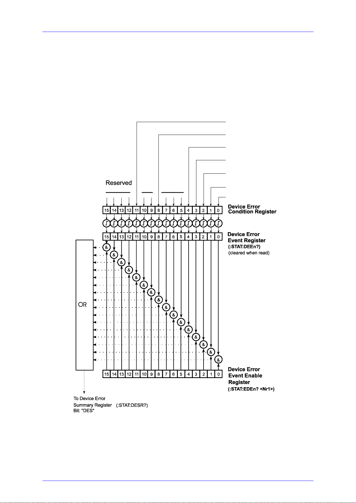
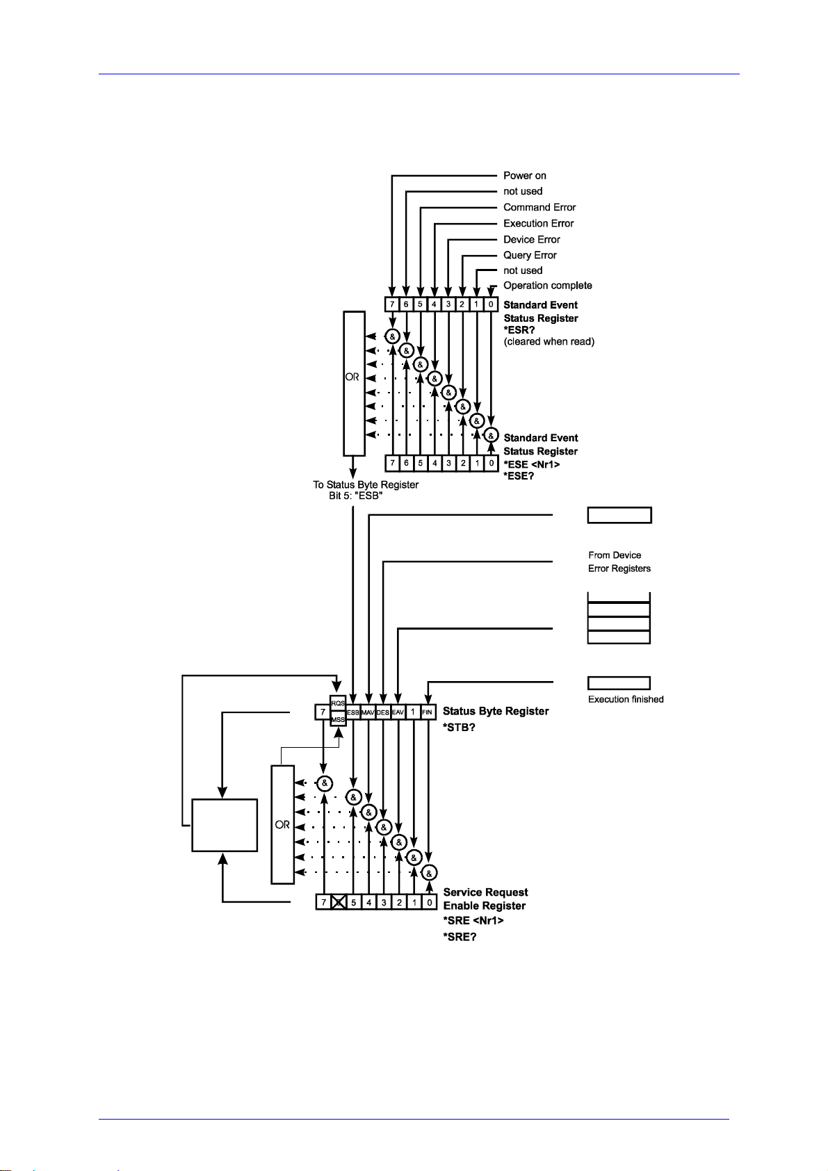
The MLC8xxxx modules provide three 16 bit registers DEC, DEE and EDE (see
Figure 18) and four 8 bit registers ESR, STB, ESE and SRE (see Figure 19) to
program various service request functions and status reporting.
Power limit
Power Supply Error
Temperature out
of window (with TEC)
Current limit
Interlock Open
Open Circuit (LD)
Over Temperature
(:STAT:DECn?)
n: Slot number
(Please refer to the IEEE488.2-1992 standard chapter 11)
Figure 18 The MLC8xxx device error registers DEC, DEE and EDE
MLC8xxx / page 58
Artisan Technology Group - Quality Instrumentation ... Guaranteed | (888) 88-SOURCE | www.artisantg.com
Page 66
3.4 Status reporting.
Service
Request
Generation
Output buffer
{
{
{
ERROR Queue
{
{
or serial poll
{
Figure 19 The PRO8000 (-4) / PRO800 register ESR, ESE, STB and SRE
MLC8xxx / page 59
Artisan Technology Group - Quality Instrumentation ... Guaranteed | (888) 88-SOURCE | www.artisantg.com
Page 67

3.4 Status reporting.
3.4.1 Standard event status register (ESR)
The bits of this register represent the following standard events:
Power on This event bit indicates, that an off to on transition has
occurred in the power supply. So it is high after turning on
the device for the first time.
User request (Not used)
Command error A command error occurred.
Execution error An execution error occurred.
Device dependent error A device dependent error occurred.
Query error A query error occurred.
Request control (Not used)
Operation complete Can be set with "*OPC".
The ESR can be read directly with the command "*ESR?". This read command
clears the ESR. The content of the ESR can not be set.
The bits are active high.
3.4.2 Standard event status enable register (ESE)
The bits of the ESE are used to select, which bits of the ESR shall influence bit 5
(ESB) of the STB. The 8 bits of the ESE are combined with the according 8 bits of
the ESR via a wired “AND”-function. These 8 results are combined with a logical
“OR”-function, so that any "hit" leads to a logical 1 in bit 5 (ESB) of the STB. As any
bit of the STB can assert an SRQ, every event (bit of the ESR) can be used to assert
an SRQ.
MLC8xxx / page 60
Artisan Technology Group - Quality Instrumentation ... Guaranteed | (888) 88-SOURCE | www.artisantg.com
Page 68

3.4 Status reporting.
3.4.3 Status byte register (STB)
The bits of this register are showing the status of the PRO8000 (-4) / PRO800.
RQS RQS: Request service message: Shows, that this device
has asserted SRQ (read via serial poll).
MSS Master summary status: Shows that this device requests a
service (read via "*STB?").
MAV (Message AVailable) This bit is high after a query request,
as a result "waits" in the output queue to be fetched. It is
low, if the output queue is empty.
DES (Device Error Status) This bit is high after a device error
occurred. Which device errors will set this bit is defined
with the EDE.
EAV (Error AVailable) This bit is high as long as there are
errors in the error queue.
FIN (command FINished) This bit is high, after a command has
finished and all bits of the STB have been set.
The STB can be read directly with the command "*STB?". The content of the STB
can not be set. The bits are active high.
All bits except bit 6 of the STB can be used to assert a service request (SRQ)
(Please refer to 3.4.5). Alternatively the SRQ can be recognized using the command
"*STB?" (Please refer to 3.4.6) or by serial poll (Please refer to 3.4.7).
3.4.4 Service request enable register (SRE)
The bits of the SRE are used to select, which bits of the STB shall assert an SRQ.
Bit 0, 1, 2, 3, 4, 5 and 7 of the STB are related to the according 7 bits of the SRE by
logical “AND”. These 7 results are combined by a logical "OR", so that any "hit" leads
to a logical 1 in bit 6 of the STB and asserts an SRQ.
MLC8xxx / page 61
Artisan Technology Group - Quality Instrumentation ... Guaranteed | (888) 88-SOURCE | www.artisantg.com
Page 69

3.4 Status reporting.
3.4.5 Reading the STB by detecting SRQ
If an SRQ is asserted (see 3.4.4) bit 6 of the STB is set to logical 1, so that the
controller can detect which device asserted the SRQ by auto serial polling.
3.4.6 Reading the STB by "*STB?" command
If the controller does not "listen" to SRQ’s at all, the service request can be detected
by reading the status byte with the command "*STB?".
If bit 6 is logical 1, a service request was asserted.
3.4.7 Reading the STB by serial poll
If the controller does not support auto serial poll, the service request can also be
detected via manual serial poll.
If bit 6 is logical 1, a service request was asserted.
MLC8xxx / page 62
Artisan Technology Group - Quality Instrumentation ... Guaranteed | (888) 88-SOURCE | www.artisantg.com
Page 70

3.4 Status reporting.
3.4.8 Device error condition register (DEC)
The bits of this register show the errors, that occur during operation (operation
errors). The bits are active high.
If the error disappears, the bits are reset to low.
For MLC8xxx laser diode controller modules bits 0 ... 4, 8 and 11 are used:
(0) Over temperature Laser temperature too high. Wait until the module has
cooled down. Maintain proper air flow.
(1) Open circuit Laser diode circuit is open.
(2) Interlock open The interlock has opened or path resistance is >430 Ω.
(3) Current limit The current limit is reached and the protection circuit is
active now. Noise and drift specs are not valid any more.
(4) Temperature out of window Appropriate laser temperature (controlled by
an TEC-module) is out of specified window.
(8) Power supply error Internal power supply error.
(11) Power limit The given hard- or software power limit is reached.
The DEC can be read but not set. Reading does not clear the DEC.
3.4.9 Device error event register (DEE)
The bits of this register hold the errors, that occurred during operation (operation
errors). So each bit of the DEC sets the according bit of the DEE.
The DEE can be read but not set. Reading clears the DEE.
MLC8xxx / page 63
Artisan Technology Group - Quality Instrumentation ... Guaranteed | (888) 88-SOURCE | www.artisantg.com
Page 71

3.4 Status reporting.
3.4.10 Device error event enable register (EDE)
The bits of the EDE are used to select, which bits of the DEE shall influence bit 3
(DES) of the STB. The 8 bits of the EDE are related by logical "AND" to the according
8 bits of the DEE. This 8 results are connected by logical "OR", so that any "hit" leads
to a logical 1 in bit 3 (DES) of the STB. As any bit of the STB can assert an SRQ,
every error (bit of the DEE) can be used to assert an SRQ.
MLC8xxx / page 64
Artisan Technology Group - Quality Instrumentation ... Guaranteed | (888) 88-SOURCE | www.artisantg.com
Page 72

4.1 General remarks
4 Service and Maintenance
4.1 General remarks
You should regularly control the correct function of the interlock.
With the laser in operation, disrupt the interlock connection: the laser output must go
into “OFF” state immediately.
Besides the above mentioned point the MLC8xxx modules do not need any
further maintenance by the user.
If highest precision of measurements is vital to you, you should have recalibrated the
MLC8xxx module about every two years.
MLC8xxx / page 65
Artisan Technology Group - Quality Instrumentation ... Guaranteed | (888) 88-SOURCE | www.artisantg.com
Page 73

4.2 Troubleshooting
4.2 Troubleshooting
In case that one module of your PRO8000 (-4) / PRO800 system shows malfunction
please check the following items:
Module does not work at all (no display on the mainframe):
Mainframe PRO8000 (-4) / PRO800 connected properly to the mains?
Connect the PRO8000 (-4) / PRO800 to the power line, take care of the
right voltage setting of your mainframe.
Mainframe PRO8000 (-4) / PRO800 turned on?
Turn on your PRO8000 (-4) / PRO800 with the key mains-switch.
Control the fuse at the rear panel of the PRO8000 (-4) / PRO800 mainframe.
If blown up, replace the fuse by the correct type
(refer to your PRO8000 (-4) / PRO800 mainframe operating manual to select
the appropriate fuse)
The PRO8000 (-4) / PRO800 display works, but not the module:
Is the module inserted correctly and are all mounting screws tightened?
Insert the module in the desired slot and tighten all
mounting screws
properly.
MLC8xxx / page 66
Artisan Technology Group - Quality Instrumentation ... Guaranteed | (888) 88-SOURCE | www.artisantg.com
Page 74

4.2 Troubleshooting
You don’t get the desired laser output power
Is the interlock closed?
Control the resistance between the interlock pins of the connector jack not
to be more than 430 Ω.
(refer to section 1.7.6, “ Connecting interlock and status display” on page
21)
Do you have selected the desired module?
(The LED “SEL” on the front panel of the module must be on)
Select the desired module on the display by means of the up- and down
arrow keys.
Do you have selected the desired port?
Select the desired port for input on the display by means of the up- and
down arrow keys or by the ":PORT <NR1>" command.
Do you have turned on the laser output in the main menu or one of the sub-
menus?
Change the status setting from “off” to “on”.
The LED “ON” on the front panel of the module must be on
Is the hardware limit I
Adjust the hardware limit I
set to 0?
LIM
by means of the potentiometer on the
LIM
MLC8xxx front panel
Is the laser current I
of the corresponding port set to 0?
PS
Adjust the laser current in the channel menu to the desired value.
Is the laser diode installed properly?
Control the connection cable.
MLC8xxx / page 67
Artisan Technology Group - Quality Instrumentation ... Guaranteed | (888) 88-SOURCE | www.artisantg.com
Page 75

4.2 Troubleshooting
Is the laser diode poled correctly?
If not, change the polarity of the laser diode corresponding to the type of
MLC-module used (AG or CG)
Is the photo diode connected properly?
Check the connecting cable.
Do you use a temperature window with inappropriate setting or with no TEC
connected?
Change settings, install TEC or turn off the window function
If you don’t find the error source by means of the trouble shooting list or if more
modules work erratic please first connect the Thorlabs-Hotline
([email protected]) before sending the whole PRO8000 (-4) / 800 system for
checkup and repair to Thorlabs-Germany.
(refer to section 5.4, “Addresses ” on page 73
MLC8xxx / page 68
Artisan Technology Group - Quality Instrumentation ... Guaranteed | (888) 88-SOURCE | www.artisantg.com
Page 76

5.1 List of abbreviations
5 Listings
5.1 List of abbreviations
The following abbreviations are used in this manual:
AC Alternating Current
ADC A
nalog to Digital Converter
AG Anode Ground
CG Cathode Ground
CLR CLeaR
CR Carriage Return
CRD C
haracter Response Data
DAC Digital to Analog Converter
DC Direct Current
DCL Device Clear
DEC Device Error Condition Register
DEE Device Error Event Register
DES Device Error Status
EAV Error AVailable
EDE Enable Device Error Event Register
EDFA E
rbium Doped Fiber Amplifier
ELCH ELectrical Characterization
EOI End Of Information
ESE Standard Event Status Enable register
ESR Event Status Register
FIN Command FIN
ished
GET Group Execute Trigger
GTL Go To Local
IEEE Institute for Electrical and Electronic Engineering
LD Laser Diode
LDC L
LED L
aser Diode Controller
ight Emitting Diode
LF Line Feed
LLO Local Lockout
LS Laser Source Module
NR1 Numeric Response data of type 1
MLC8xxx / page 69
Artisan Technology Group - Quality Instrumentation ... Guaranteed | (888) 88-SOURCE | www.artisantg.com
Page 77

5.1 List of abbreviations
NR2 Numeric Response data of type 2
NR3 Numeric Response data of type 3
MAV Message AVailable)
MSS Master Summary Status
OTP Over TemPerature
PC Personal Computer
PD Photo Diode
RQS ReQuest Service Message
SDC Selected Device Clear
SEL SELect
SRE Service Request Enable Register
SRQ Service ReQuest
STB STatus Byte Register
SW Soft Ware
TEC ThermoElectric Cooler (Peltier Element)
TRG TRiGger
MLC8xxx / page 70
Artisan Technology Group - Quality Instrumentation ... Guaranteed | (888) 88-SOURCE | www.artisantg.com
Page 78

5.2 List of figures
5.2 List of figures
Figure 1 Operating elements on front panel. 9
Figure 2 Pinning of the MLC8xxx output connector 11
Figure 3 Principle connections for every laser 12
Figure 4 Laser AG / photo diode CG, no bias 18
Figure 5 Laser AG / photo diode AG, no bias 18
Figure 6 Laser AG / photo diode floating, no bias 19
Figure 7 Laser AG / photo diode CG, 5V bias 19
Figure 8 Laser AG / photo diode AG, 5V bias 20
Figure 9 Laser AG / photo diode floating, 5V bias 20
Figure 10 Pinning of the MLC8xxx output connector 22
Figure 11 Principle connections for every laser 23
Figure 12 Laser CG / photo diode CG, no bias 29
Figure 13 Laser CG / photo diode AG, no bias 29
Figure 14 Laser CG / photo diode floating, no bias 30
Figure 15 Laser CG / photo diode CG, with 5V bias 31
Figure 16 Laser CG / photo diode AG 31
Figure 17 Laser CG / photo diode floating, 5V bias 32
Figure 18 The MLC8xxx device error registers DEC, DEE and EDE 58
Figure 19 The PRO8000 (-4) / PRO800 register ESR, ESE, STB and SRE 59
MLC8xxx / page 71
Artisan Technology Group - Quality Instrumentation ... Guaranteed | (888) 88-SOURCE | www.artisantg.com
Page 79
5.3 Certifications and compliances
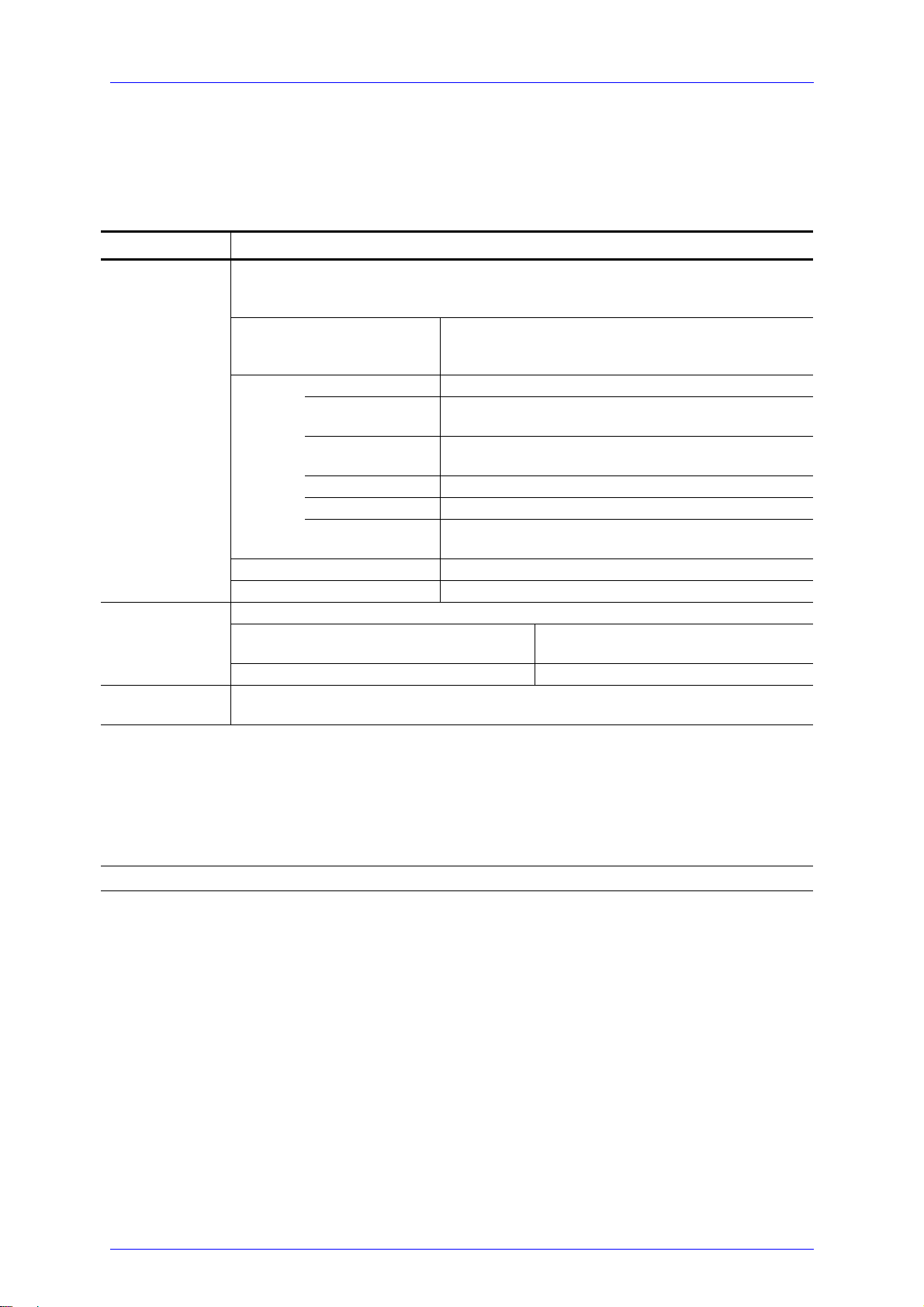
5.3 Certifications and compliances
Certifications and compliances
Category Standards or description
EC Declaration of
Conformity - EMC
EN 61326 EMC requirements for Class A electrical equipment for
IEC 61000-4-2 Electrostatic Discharge Immunity (Performance criterion C)
IEC 61000-4-3 Radiated RF Electromagnetic Field Immunity (Performance
IEC 61000-4-4 Electrical Fast Transient / Burst Immunity (Performance
IEC 61000-4-5 Power Line Surge Immunity (Performance criterion C)
IEC 61000-4-6 Conducted RF Immunity (Performance criterion B)
IEC 61000-4-11 Voltage Dips and Interruptions Immunity (Performance
EN 61000-3-2 AC Power Line Harmonic Emissions
Australia /
New Zealand
Declaration of
Conformity - EMC
FCC EMC
Compliance
1
Compliance demonstrated using high-quality shielded interface cables, including with a custom-made shielded cable
installed at the LD OUT port.
2
Compliance demonstrated with the MLC8x series modules installed in the Thorlabs PRO8x series of mainframes.
3
Emissions, which exceed the levels required by these standards, may occur when this equipment is connected to a test
object.
4
Minimum Immunity Test requirement.
Meets intent of Directive 89/336/EEC for Electromagnetic Compatibility. Compliance was
demonstrated to the following specifications as listed in the Official Journal of the European
Communities:
measurement, control and laboratory use, including Class A
Radiated and Conducted Emissions
1,2,3
and Immunity.
1,2,4
criterion B)
criterion C)
criterion C)
Complies with the Radiocommunications Act and demonstrated per EMC Emission standard
1,2,3
:
AS/NZS 2064 Industrial, Scientific, and Medical Equipment:
1992
Emissions comply with the Class A Limits of FCC Code of Federal Regulations 47, Part 15, Subpart
1,2,3
B
.
MLC8xxx / page 72
Artisan Technology Group - Quality Instrumentation ... Guaranteed | (888) 88-SOURCE | www.artisantg.com
Page 80

5.4 Addresses
5.4 Addresses
Thorlabs GmbH
Gauss-Strasse 11
D-85757 Karlsfeld
Fed. Rep. of Germany
Tel.: +49 (0)81 31 / 5956-0
Fax: +49 (0)81 31 / 5956 99
Internet: http://www.thorlabs.com
Technical Hotline: [email protected]
Our company is also represented by several distributors and sales offices throughout
the world.
Please call our hotline, send an E-mail to ask for your nearest distributor or just visit
our homepage http://www.thorlabs.com
MLC8xxx / page 73
Artisan Technology Group - Quality Instrumentation ... Guaranteed | (888) 88-SOURCE | www.artisantg.com
Page 81

Artisan Technology Group is your source for quality
new and certied-used/pre-owned equipment
• FAST SHIPPING AND
DELIVERY
• TENS OF THOUSANDS OF
IN-STOCK ITEMS
• EQUIPMENT DEMOS
• HUNDREDS OF
MANUFACTURERS
SUPPORTED
• LEASING/MONTHLY
RENTALS
• ITAR CERTIFIED
SECURE ASSET SOLUTIONS
SERVICE CENTER REPAIRS
Experienced engineers and technicians on staff
at our full-service, in-house repair center
Instra
Remotely inspect equipment before purchasing with
our interactive website at www.instraview.com
Contact us: (888) 88-SOURCE | [email protected] | www.artisantg.com
SM
REMOTE INSPECTION
View
WE BUY USED EQUIPMENT
Sell your excess, underutilized, and idle used equipment
We also offer credit for buy-backs and trade-ins
www.artisantg.com/WeBuyEquipment
LOOKING FOR MORE INFORMATION?
Visit us on the web at www.artisantg.com for more
information on price quotations, drivers, technical
specications, manuals, and documentation
 Loading...