


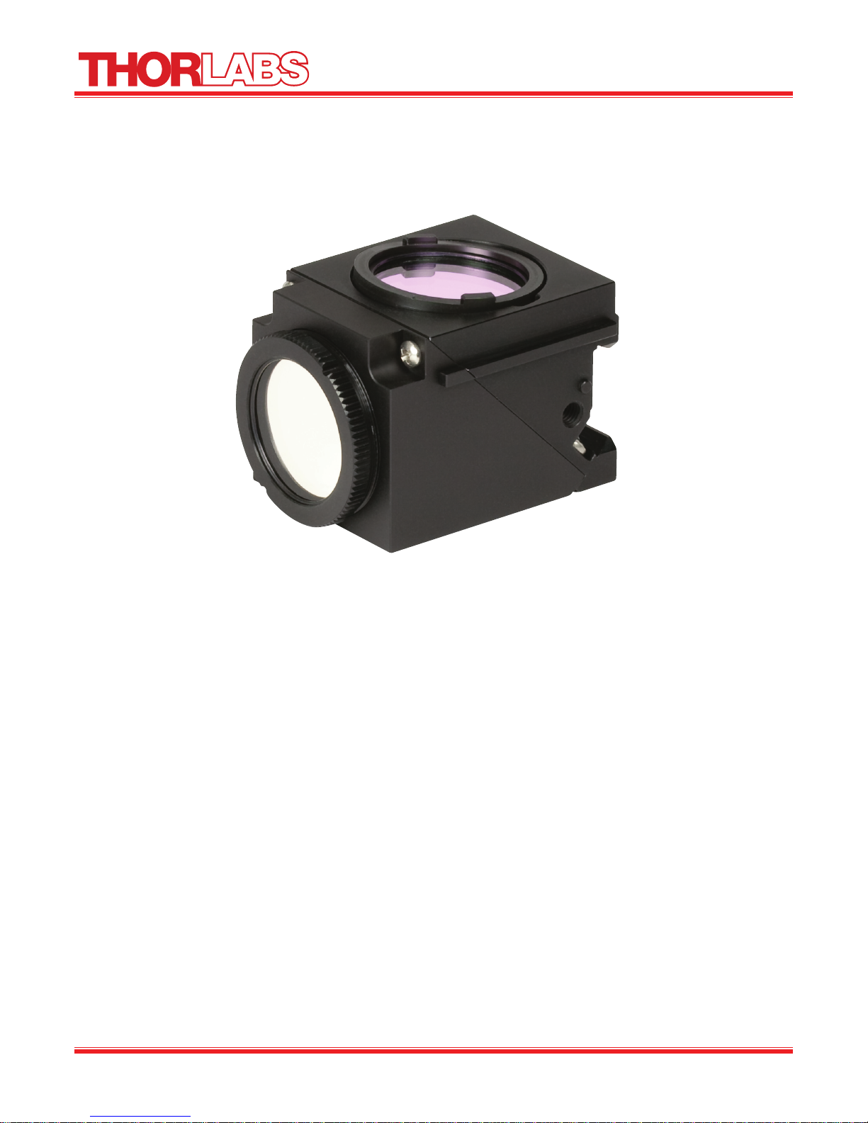
MDFM-QFXL
Nikon E200-E1000, TS100,
TE200, and TE300
Microscopy Filter Cube
Assembly Manual

Nikon QFXL Filter Cube Assembly Manual
Table of Contents
Part 1. Safety ............................................................................................................................................3
Part 2. Assembly Instructions ..................................................................................................................3
Part 3. Regulatory ....................................................................................................................................9
3.1. Waste Treatment is Your Own Responsibility ...................................................................................... 9
3.2. Ecological Background ............................................................................................................................ 9
Part 4. Thorlabs Worldwide Contacts ...................................................................................................10
21398-D02 Rev A, September 22, 2010 Page 2 www.thorlabs.com

Nikon QFXL Filter Cube Assembly Manual
Part 1. Safety
All statements regarding safety of operation and technical data in this instruction manual will only apply
when the unit is assembled and operated correctly. Handle all optics with care. Gloves are recommended
for optic installations. Take care when tightening optics, as overtightening optics may cause the optic to
break or shatter.
Part 2. Assembly Instructions
Emitter Side
Step 1
Carefully unpack the Nikon MDFM-QFXL
Filter Cube assembly. Take note where
the emitter and exciter sides of the cube
are (see Figure 1).
Exciter Side
Step 2
Unscrew the exciter retaining ring, noting
that the mounting adapter is inside the exciter
retaining ring. The mounting adapter fits
into the recess in the fiter cube and should
be oriented with the thin side facing into the
filter cube.
Remove the emitter retaining ring by twisting
the ring. Note the orientation of the emitter
ring as shown in Figure 2.
Exciter Mounting
Adapter
Figure 1. MDFM-QFXL Filter Cube
Emitter Retainer
Ring
Exciter
Retainer Ring
21398-D02 Rev A, September 22, 2010 Page 3 www.thorlabs.com
Figure 2. Exciter retaining ring and mounting sleeve

Nikon QFXL Filter Cube Assembly Manual
Step 3
Unscrew the four screws holding the emitter and exciter halves together. The location of the screws is
shown in Figure 3. Note the screw lengths, the two screws on the exciter side are longer than the screws
on the backside of the cube.
Figure 3. Disassembling the filter cube
Step 4
Separate the two halves as shown in Figure 4. The exciter half is shown on the left, and the emitter side
is shown on the right. The dichroic mirror retainer spring may already be installed in the recess in the
emitter half. If so, remove the spring so the dichroic mirror can be installed.
Exciter Filter
Half
Emitter Filter
Half
Recess for
the Dichroic
Mirror
21398-D02 Rev A, September 22, 2010 Page 4 www.thorlabs.com
Figure 4. Separating the filter cube halves

Nikon QFXL Filter Cube Assembly Manual
(
Step 5
The MDFM-QFXL Filter Cube holds a standard set of Thorlabs MDF Series Dichroic Mirror, Emission,
and Excitation Filter Set, sold separately. The MDF-CY3.5 Filter set is shown in Figure 5.
Dichroic
Mirror
Emission
Filter
Excitation
Filter
Figure 5. Dichroic mirror set
The emission and excitation filters can be easily differentiated by the thickness of the filter mount rings:
emission (3.5 mm) and excitation (5.0 mm). Note that the dichroic mirror has a coated and an uncoated
side (see Figure 6).
Coating
Observed to
the Edge
See Edge
Transmission
Reflective
Coated) Side
Figure 6. Dichroic mirror orientation
Uncoated Side
When held at an angle, the coated side will appear uniform in reflection all the way to the edge. The
uncoated side, when held at the same angle, will not have a uniform reflection near the edge. There will
be a band of transmission that appears through the uncoated substrate. It is important to determine the
coated and uncoated sides of the dichroic mirror as there is only one orientation that will work with the
Filter Cube.
21398-D02 Rev A, September 22, 2010 Page 5 www.thorlabs.com

Nikon QFXL Filter Cube Assembly Manual
Step 6
Place the dichroic mirror in the recess provided in the filter cube such that the reflective (coated) surface
faces UP. Place the dichroic mirror spring clip over the mirrors.
Reflective
Side Must
Dichroic Mirror
Spring Clip
Face Up
Dichroic Mirror
Emitter Half
Figure 7. Dichroic mirror (Part # MD568) placed in the emitter half, reflective side up. Place the
dichroic mirror spring clip over the mirror.
Step 7
Align the exciter filter half with the notch on the emitter half as shown in Figure 8. Alternate tightening
between the four assembly screws taking care not to allow movement of the dichroic mirror.
Check the orientation of the dichroic mirror by looking into the exciter and emitter sides of the filter
cube. The reflective (coated) side should face the exciter side of the cube.
Exciter Reflective
(Coated) Side
Exciter
Half
Alignment
Guide
Figure 8. Reassembling the filter cube and checking dichroic mirror (Part # MD568) orientation
21398-D02 Rev A, September 22, 2010 Page 6 www.thorlabs.com
Emitter
Uncoated Side

Nikon QFXL Filter Cube Assembly Manual
Step 8
Orient the filter cube so the emission side is
facing up. Insert the emission filter in the
filter cube with the arrow facing away from
the cube as shown in Figure 9. Place the
emission filter retaining ring on the filter
and twist to secure. The retaining ring should
rotate clockwise approximately 1/8 turn to
secure the filter.
Important Note: The emission filter will not
be parallel with the face of the cube as shown
in Figure 9.
Retainer
Ring
Emission
Filter
Figure 9. Installing the emission filter
Step 9
Orient the filter cube so the excitation side is
facing up. Insert the exciter adapter into the
filter cube with the thinner section facing into
the cube. Insert the excitation filter onto the
adapter with the arrow pointing towards the
cube and dichroic mirror. The orientation of the
adapter and excitation filter is shown in
Figure 10.
Slowly thread the exciter retaining ring, onto the
filter cube. The retaining ring should thread
easily onto the filter cube and over the excitation
filter and adapter.
Important Note: The retaining ring may not
thread completely onto the filter cube. This is
fine and should not affect the performance of
the filter cube.
Retaining
Ring
Excitation
Filter
Filter
Adapter
Exciter
Side
21398-D02 Rev A, September 22, 2010 Page 7 www.thorlabs.com
Figure 10. Excitation filter orientation and mounting
Nikon QFXL Filter Cube Assembly Manual
Step 10
The completed Nikon MDFM-QFXL Filter Cube is shown in Figure 11.
Figure 11. The MDFM-QFXL Filter Cube with emission filter, excitation filter, and dichroic mirror
installed
21398-D02 Rev A, September 22, 2010 Page 8 www.thorlabs.com

Nikon QFXL Filter Cube Assembly Manual
Part 3. Regulatory
As required by the WEEE (Waste Electrical and Electronic Equipment Directive) of the European
Community and the corresponding national laws, Thorlabs offers all end users in the EC the possibility
to return “end of life” units without incurring disposal charges.
• This offer is valid for Thorlabs electrical and electronic equipment:
• Sold after August 13, 2005
• Marked correspondingly with the crossed out “wheelie bin” logo (see right)
• Sold to a company or institute within the EC
• Currently owned by a company or institute within the EC
Wheelie Bin Logo
• Still complete, not disassembled and not contaminated
As the WEEE directive applies to self-contained operational electrical and electronic products, this end
of life take back service does not refer to other Thorlabs products, such as:
• Pure OEM products, that means assemblies to be built into a unit by the user (e. g. OEM laser
driver cards)
• Components
• Mechanics and optics
• Left over parts of units disassembled by the user (PCB’s, housings etc.).
If you wish to return a Thorlabs unit for waste recovery, please contact Thorlabs or your nearest dealer
for further information.
3.1. Waste Treatment is Your Own Responsibility
If you do not return an “end of life” unit to Thorlabs, you must hand it to a company specialized in waste
recovery. Do not dispose of the unit in a litter bin or at a public waste disposal site.
3.2. Ecological Background
It is well known that WEEE pollutes the environment by releasing toxic products during decomposition.
The aim of the European RoHS directive is to reduce the content of toxic substances in electronic
products in the future.
The intent of the WEEE directive is to enforce the recycling of WEEE. A controlled recycling of end of
life products will thereby avoid negative impacts on the environment.
21398-D02 Rev A, September 22, 2010 Page 9 www.thorlabs.com

Nikon QFXL Filter Cube Assembly Manual
Part 4. Thorlabs Worldwide Contacts
USA, Canada, and South America
Thorlabs, Inc.
435 Route 206
Newton, NJ 07860
USA
Tel: 973-579-7227
Fax: 973-300-3600
www.thorlabs.com
email: feedback@thorlabs.com
Europe
Thorlabs GmbH
Hans-Böckler-Str. 6
85221 Dachau
Germany
Tel: +49-(0)8131-5956-0
Fax: +49-(0)8131-5956-99
www.thorlabs.de
email: Europe@thorlabs.com
France
Thorlabs SAS
109, rue des Côtes
78600 Maisons-Laffitte
France
Tel: +33 (0) 970 444 844
Fax: +33 (0) 811 381 748
www.thorlabs.de
email: slaes.fr@thorlabs.com
Japan
Thorlabs Japan Inc.
3-6-3, Kitamachi,
Nerima-ku, Tokyo 179-0081
Japan
Tel: +81-3-6915-7701
Fax: +81-3-6915-7716
www.thorlabs.co.jp
email: sales@thorlabs.jp
UK and Ireland
Thorlabs LTD.
1 Saint Thomas Place, Ely
Cambridgeshire CB7 4EX
Great Britain
Tel: +44 (0)1353-654440
Fax: +44 (0)1353-654444
www.thorlabs.de
email: sales.uk@thorlabs.com
Scandinavia
Thorlabs Sweden AB
Box 141 94
400 20 Göteborg
Sweden
Tel: +46-31-733-30-00
Fax: +46-31-703-40-45
www.thorlabs.de
email: scandinavia@thorlabs.com
China
Thorlabs China
Oasis Middlering Centre
3 Building 712 Room
915 Zhen Bei Road
Shanghai
China
Tel: +86 (0)21-32513486
Fax: +86 (0)21-32513480
www.thorlabs.com
email: chinasales@thorlabs.com
21398-D02 Rev A, September 22, 2010 Page 10 www.thorlabs.com

Thorlabs, Inc.
435 Route 206N
Newton, NJ 07860 USA
Phone: (973) 579-7227 ♦ Fax: (973) 300-3600
www.thorlabs.com
 Loading...