


LSS10
LED Lightbox for
Laser Safety Signs
User Guide
Original Instructions

LSS10 LED Light Box
Contents
Chaper 1 Overview ..................................................................................................... 1
1.1 Introduction ........................................................................................ 1
Chaper 2 Safety .......................................................................................................... 2
2.1 Safety Information ................................................. ......................... ... 2
2.2 General Warnings .............................................................................. 2
Chaper 3 Installation .................................................................................................. 4
3.1 Mechanical Installation ...................................................................... 4
3.2 Electrical Connections ...................................................................... 4
Chaper 4 Operation .................................................................................................... 8
4.1 Control and Connection Overview ............ .. ... .................................. 8
4.2 Using the Safety Interlock .......................................... ....................... 9
4.3 Replacing the Internal Fuses .......................................................... 10
4.4 Inserting a Laser Safety Sign ..................................... ... .................. 10
4.5 Disabling the Brightness Control........................................ ... ......... 11
4.6 Cleaning............................................................................................. 11
Chaper 5 Specification ............................................................................................. 12
5.1 General Specifications .................................................................... 12
Chaper 6 Regulatory ................................................................................................ 13
6.1 Declarations Of Conformity ............................................................ 13
6.2 Waste Electrical and Electronic Equipment (WEEE) Directive .... 13
6.3 CE Certificates ................................................................................. 15
Chaper 7 Thorlabs Worldwide Contacts................................................................ 16

Chapter 1 Overview
Chapter 1 Overview
1.1 Introduction
The LSS10 Laser Safety Sign Lightbox provides a clear indication that a laser system
is in use by illuminating the laser safety sign (sold sepa rately) that states the
appropriate warning message and laser classification. The lightbox accepts any one
of the LSS10 se ries Laser Safety Signs available from our website. Signs can be
quickly interchanged making it easy to update signage to meet your cha nging laser
set up requirements.
The box operates at 100 to 240 VAC, (i.e. USA and EU regions) and has two safety
interlock options (internal and external - see Section 4.2.) th at prevent the use of
interlock-equipped laser systems unless the safety light is turned on. The external
interlock socket accepts a 2.5 mm phono jack (supplied).
The lightbox is permanently fixed to a wal l via the moun ting slots in the rear panel.
Two sets of slots are available to allow positioning of the controls for left or right
handed operation. A convenient line cord latch preven ts the AC line cord from
disengaging from the unit.
Illumination is controlled by turning a knob on the right hand side of the unit, allowing
the brightness to be adjusted to suit th e specific location of use. An internal jumper
can be activated which bypasses the external control, thereby making the brightness
tamperproof. Illumination is then controlled by a set of switches on the circuitboard see Section 4.5.
Rev A Nov 2017
Fig. 1.1 LSS10 Laser Safety Sign Lightbox
Page 1

LSS10 LED Light Box
Chapter 2 Safety
2.1 Safety Information
For the continuing safety of the operators of this equipment, and the protection of the
equipment itself, the operator should take note of the Warnings, Cautions and Notes
throughout this handbook and, where visible, on the product itself.
The following safety symbo ls may be u sed throughout the h andbook and on the
equipment itself.
Warning: Risk of Electrical Shock
Given when there is a risk of injury from electrical shock.
Warning
Given when there is a risk of injury to users.
Caution
Given when there is a risk of damage to the product.
Note
Clarification of an instruction or additional information.
2.2 General Warnings
Warning
If this equipment is used in a manner not specified by the manufacturer, the
protection provided by the equipment may be impaired. In particular, excessive
moisture may impair operation.
Spillage of fluid, such as sample solutions, should be avoided.
If spillage does occur, disconnect the power then clean up immediately using
absorbant tissue. Do not allow spilled fluid to enter the internal mechanism.
The equipment is for indoor use only.
The equipment is not designed for use in an explosive atmosphere.
Page 2 ETN037435-D02

Chapter 2 Safety
Warning: Risk of Electrical Shock
The light box is powered by mains voltages. This is hazardous and can cause
serious injury. Appropriate care should be taken when using this device.
Persons using the device must understand the hazards associated with using
high voltages and the steps necessary to avoid risk of e lectrical shock.
Particular care should be observed when adjusting or operating the unit via the
internal PCB controls.
Rev A Nov 2017
Page 3

LSS10 LED Light Box
Chapter 3 Installation
3.1 Mechanical Installation
The lightbox can be permanently fixed to a wall, via the four mounting holes in the rear
panel - see the dra wings available from www.thorlabs.com for details and
dimensions.
Caution
Screws or fittings to attach the unit to the wall are not included. Always choose
M4 (8-32) screws and fittings which are suitable for use in your wall and have
enough holding power. Do not use screws with cou ntersunk heads. If you are
uncertain, contact a specialised installer.
Note
The default configuration and labelling is for right-handed use, however the mounting
holes allow the unit to be mounted for left hand use.
Furthermore, several metalwork knockouts are provided for grommets (supplied) and
cables when hard wiring the unit into an electrical system.
Caution
The unit must be fixed securely to the wall before using the internal wiring option.
Do not use the internal wiring option when the unit is fixed via the keyed slots in
the rear panel.
3.2 Electrical Connections
Warning
The unit uses mains voltages. This is hazardous and can cause serious injury.
The unit must be installed only by suitably trained and qualified personnel who
understand the ha zards associated with using high voltages and the steps
necessary to minimize the risk of electrical shock.
The unit is conn ected to the mains power using the cab le supplied, via the IEC 14
connector on the right hand side - see Fig. 3.1.
Warning
If using a power cord other than that supplied, ensure that the cord is at least
equivalently rated (see Se ction 5.1. fo r power cord ratings) an d does not
exceed 3m in length.
Use only power cords with a factory supplied moulded IEC C13 connector. Do
not use cords fitted with rewirable connectors.
Page 4 ETN037435-D02

Chapter 3 Installation
100 - 240 VAC
50/60 Hz
15 W
A convenient line cord latch prevents the power cord disengaging from the unit. The
cord latch is supplied loose and should be fitted before the lightbox is used.
Fig. 3.1 Power supply connection panel
Although the unit is supplied preset fo r external power connections, power can be
hard wired to the internal PCB as follows:
Cautions for Hard Wiring the Unit
The unit should be hard wired only when it is permanently attached to the wall.
Only use 3-core (0.75 to 1.5 mm2) 218/318 cable to EN 50525-2-11 to hard wire
the unit.
Grommets with a flammability rating of UL94-V-1 or better must be used at the
cable exit points. Suitable grommets are supplied.
In order to preve nt accidental disconnection of cabl es, ensure that the strain
relief clamp provided is used. The clamp is fitted with two M3 x 6mm screws for
use with standard cable diameters. Two M3 x 8 mm screws are also supplied
for use with larger diameter cables.
A switch or circuit breaker must be incl uded in the installation. It must be
conveniently located and easily reached, and must be clearly marked a s the
disconnecting device for the equipment.
1) Ensure that the unit is disconnected from mains power.
2) Using a PZ1 screwdriver or other suitable tool, remove the six M3 PoziDriv screws
securing the front panel.
Rev A Nov 2017
Page 5

LSS10 LED Light Box
Neutral
Earth
Live
FUSES F1 and F2
0.63A, 250 VAC.
CON4
LED PANEL
R15
3) Pull to the left and forward to remove as shown in Fig. 3.2 over the page. Keep the
cover supported until the internal electrical connection is disconnected at the next
step.
Fig. 3.2 Removing the front panel
4) Unclip the connection to the LED circuit CON4 - see Fig. 3.3 then remove the panel.
5) Ensure mains power is disconnected, then move the INT/EXT jumpers at the
bottom of the PCB to the INT position as shown below.
Page 6 ETN037435-D02
Fig. 3.3 Internal mains connection

Chapter 3 Installation
Knock-outs in rear panel 4 Places
Knock-outs in side faces 3 Places
Strain relief clamp
6) Make connections using connector CON2 as shown in
knock-outs, grommets (supplied) and strain relief clamps provided to ensure that
the cable is adequately supported and restrained - see Fig. 3.4.
Fig. 3.3
. Use the cable
Fig. 3.4 Cable knock-outs and strain relief clamp locations
7) If using an internal safety interlock, perform the procedure detailed in Section 4.2.
8) Re-connect the LED circuit at CON4.
9) Refit the front panel.
10) To change from hard-wired power to using the panel connections, isolate the unit
from the mains supply, then reverse the steps previously described.
Rev A Nov 2017
Page 7

LSS10 LED Light Box
+
_
I
O
INTLK
POWER
LSS10
CB74EX UK
Chapter 4 Operation
4.1 Control and Connection Overview
The controls are located on the side panel above the power supply connections as
shown below.
BRIGHTNESS - Used to control the light intensity of the lightbox (when the external
controls (see Section 4.5.) are enabled).
INTLK - For use in laser safety applications - see Section 4.2.
POWER - Used to switch the unit on and off.
Caution
The ON/OFF switch mentioned above removes power from the internal lighting
circuit. It does not remove power from the unit itself.
Page 8 ETN037435-D02
Fig. 4.1 Controls overview

Chapter 4 Operation
laser interlock circuit
lightbox
panel
switch
interlock
relay
4.2 Using the Safety Interlock
The lightbox is fitted with an optional safety interlock output, which allows interlockequipped laser systems to be interlocked to the lightbox such that laser use is
prevented unless the lightbox is illuminated.
External interlock circuits can be connected to the lightbox interlock output externally
or internally. External circuits should not exceed 34V DC/AC, 0 .5A, and should be
electrically isolated from hazardous circuits with reinforced insulation.
External connection is achieved via the jack socket on the right hand control panel
(see Fig. 4.1) which accepts a 2.5mm phono jack (supplied). This should be wired into
the laser interlock circuit as shown in Fig. 4.2.
Fig. 4.2 Jackplug interlock wiring
Caution
When soldering the interlock jack plug, ensure that the contacts are prope rly
isolated from each other.
DO NOT con nect/disconnect the interlock jackplug when the unit is switched
ON and illuminated.
Rev A Nov 2017
Page 9

LSS10 LED Light Box
INTERLOCK
CON6
laser external
interlock circuit
interlock
relay
lightbox
panel
switch
Internal connection is achieved by hard-wiring to the terminal block provided on the
PCB as shown in Fig. 4.3.
4.3 Replacing the Internal Fuses
Fig. 4.3 PCB interlock wiring
The ON/OFF switch on the panel controls power to the interlock relay, and completes
the interlock circuit when the switched ON.
Warning
The unit uses mains voltages. This is hazardous and can cause serious injury.
The fuses must be replaced only by suitably trained and qualified personnel
who understand the hazards associated with using high voltages and the steps
necessary to minimize the risk of electrical shock.
In case of an internal fuse blow, the fuse should be replaced as follows:
1) Remove power from the unit.
2) Remove the front panel - see Fig. 3.2.
3) Locate the broken fuse - see Fig. 3.3
4) Replace the fuse with another of the same type, 0.63A (T) 250 VAC.
5) Refit the front panel.
Page 10 ETN037435-D02

4.4 Inserting a Laser Safety Sign
Safety signs are inserted through a hinged flap as shown below.
Chapter 4 Operation
Fig. 4.4 Inserting a laser safety sign
4.5 Disabling the External Brightness Control
Warning
The internal circuit board exposes mains voltages. This is hazardous and can
cause serious injury. Adjustment of the internal controls must be pe rformed
only by suitabl y trained and qualified personnel who understand the hazards
associated with using high voltages and the steps necessary to m inimize the
risk of electrical shock.
To avoid unwanted tampering with the brightness setting, the unit can be configured
such that the external control is bypassed, and brightness is set internally.
1) Isolate the unit from mains power.
2) Remove the front Panel - see Fig. 3.2.
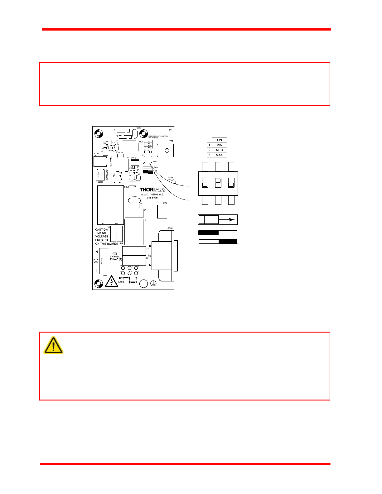
3) Move switch SW3 to the INT position as shown below.
Rev A Nov 2017
Page 11
LSS10 LED Light Box
SW3
EXT
INT
SW1
12 3
4) Adjust the brightness by setting switch SW1 to MIN, MED or MAX. Fig. 4.5 shows
the brightness set to MED.
Note
The ‘MIN’ setting corresponds to the brightness level set to minimum using the
control panel pot. Similarly, the ‘MAX’ setting corresponds to the max brightness
level set using the control panel pot.
5) Refit the front panel.
Fig. 4.5 Switching to internal brightness adjustment
4.6 Cleaning
Warnings
Disconnect the power supply before cleaning the unit.
Never allow water to get inside the case.
Do not saturate the unit.
Do not use any type of abrasive pad, scouring powder or solvent, e.g. alcohol
or benzene.
The unit may be clean ed with a soft cloth, lightly dampened with water or a mild
detergent.
Page 12 ETN037435-D02

Chapter 5 Specification
Chapter 5 Specification
5.1 General Specifications
Parameter Value
Emitted Light Color White (Daylight - 5300K)
Voltage 100 - 240 VAC, 50/60 Hz
Power 8W (Minimum Brightness) to 15 W (Max Brightness)
Internal Fuses Qty 2, 0.63A (T) 250 VAC
Operating Temperature Range 5 to 40 °C
Dimensions (W x D x H) 362.0 x 257 x 50 mm (14.25" x 10.12" x 1.97")
Weight 3.3 Kg
Power Cord Ratings
Cord Type US UK EU
Voltage Rating 125 VAC 250 VAC 250 VAC
Fuse Rating 10 A 10 A 5 A
Temperature Rating 60 °C (140 °F) 70 °C (158 °F) 70 °C (158 °F)
Connector IEC 60320 C13, Moulded
Rev A Nov 2017
Page 13

LSS10 LED Light Box
Chapter 6 Regulatory
6.1 Declarations Of Conformity
6.1.1 For Customers in Europe
See Section 6.2.
6.1.2 For Customers In The USA
This equipment has been tested and found to comply with the li mits for a Class A
digital device, persuant to part 15 of the FCC rules. These limits are designed to
provide reasonable protection against harmful interference when the equipment is
operated in a commercial environment. This equipment generates, uses and can
radiate radio frequency energy and, if not installed and used in accordance with the
instruction manual, may cause harmful interference to radio communications.
Operation of this equipment in a residential area is likely to cause harmful interference
in which case the user will be required to correct the interference at his own expense.
Changes or modifications not expressly approved by the compan y could void the
user’s authority to operate the equipment.
Page 14 ETN037435-D02

6.2 CE Certificate
Chapter 6 Regulatory
Rev A Nov 2017
Page 15

LSS10 LED Light Box
Chapter 7 Thorlabs Worldwide Contacts
UK and Ireland
USA, Canada, and South America
Thorlabs, Inc.
56 Sparta Avenue
Newton, NJ 07860
USA
Tel: 973-300-3000
Fax: 973-300-3600
www.thorlabs.com
www.thorlabs.us (West Coast)
Email: sales@thorlabs.com
Support: techsupport@thorlabs.com
Europe
Thorlabs GmbH
Hans-Böckler-Str. 6
85221 Dachau / Munich
Germany
Tel: +49-(0) 8131-5956-0
Fax: +49-(0) 8131-5956-99
www.thorlabs.de
Email: europe@thorlabs.com
France
Thorlabs SAS
109, rue des Côtes
78600 Maisons-Laffitte
France
Tel: +33 (0) 970 444 844
Fax: +33 (0) 825 744 800
www.thorlabs.com
Email: sales.fr@thorlabs.com
Japan
Thorlabs Japan, Inc.
3-6-3, Kitamachi,
Nerima-ku, Tokyo 179-0081
Japan
Tel: +81Fax: +81-3-6915-7716
www.thorlabs.co.jp
Email: sales@thorlabs.jp
3-6915-7701
Thorlabs Ltd.
1 Saint Thomas Place
Ely CB7 4EX
Great Britain
Tel: +44 (0)1353-654440
Fax: +44 (0)1353-654444
www.thorlabs.de
email: sales@uk.thorlabs.com
Support: techsupport.uk@thorlabs.com
Scandinavia
Thorlabs Sweden AB
Bergfotsgatan 7
431 35 Mölndal
Sweden
Tel: +46-31-733-30-00
Fax: +46-31-703-40-45
www.thorlabs.com
Email: scandinavia@thorlabs.com
Brazil
Thorlabs Vendas de Fotônicos Ltda.
Rua Riachuelo, 171
São Carlos, SP 13560-110
Brazil
Tel: +55-16-3413 7062
Fax: +55-16-3413 7064
www.thorlabs.com
Email: brasil@thorlabs.com
China
Thorlabs China
Room A101, No. 100, Lane 2891
uth Qilianshan Road
So
Putuo Distri
Shanghai
China
Tel: +86 (0) 21-60561122
Fax: +86 (0) 21-32513480
www.thorlabschina.cn
Email: chinasales@thorlabs.com
ct
Thorlabs verifies our compliance with the WEEE (Waste Electrical and Electronic
Equipment) directive of the European Community and the corresponding national
laws. Accordingly, all end users in the EC may return "end of life" Annex I category
electrical and electronic equipment sold after August 13, 2005 to Thorlabs, without
incurring disposal charges. Eligible units are marked with the crossed out "wheelie
bin" logo (see right), were sold to and are currently owned by a company or institute
within the EC, and are not dissembled or contaminated. Contact Thorlabs for more
information. Waste treatment is your own responsibility. "End of life" units must be
returned to Thorlabs or handed to a company specializing in waste recovery. Do not
dispose of the unit in a litter bin or at a public waste disposal site.
Page 16 ETN037435-D02

www.thorlabs.com
 Loading...