


Operation Manual
Thorlabs Instrumentation
Laser Sources
LS5000 Series
2009

Version: 2.15
Date: 19.10.2009
Copyright© 2009, Thorlabs

Contents Page
1 General description 1
1.1 Safety 1
1.2 Features 5
1.3 Technical data 7
1.4 Operating elements at the front of the card 9
1.5 Connecting an optical fiber 9
1.6 Installing and removing cards 10
2 Getting Started 11
2.1 Preconditions 11
2.2 The Graphics User Interface (GUI) 12
2.2.1 Start the GUI 12
3 Operating the LS5000 16
3.1 Operating elements in the main window 16
3.1.1 Wavelength Control 16
3.1.2 Power Control 17
3.1.3 The Modulation Control 17
3.1.4 The Status messages field 18
3.2 Menu items 18
3.2.1 The ‘File’ menu 18
3.2.2 The ‘Connection’ menu 19
3.2.3 The cards menu 20
3.2.4 The ‘Preferences’ menu 21
4 Service and Maintenance 23
4.1 Troubleshooting 23
4.2 Recalibration 23
5 Appendix 24
5.1 Warranty 24
5.2 Thorlabs “End of Life” policy (WEEE) 25
5.2.1 Waste treatment on your own responsibility 25
5.2.2 Ecological background 26
5.3 List of Acronyms and abbreviations 27
5.4 List of figures 28
5.5 List of possible status messages 29
5.6 Certifications and compliances 30
5.7 Copyright 32
5.8 Addresses 33

We aim to develop and produce the best solution for your application in the
field of optical measurement technique. To help us to come up to your
expectations and develop our products permanently we need your ideas and
suggestions. Therefore, please let us know about possible criticism or ideas.
We and our international partners are looking forward to hearing from you.
Thorlabs
This part of the instruction manual contains every specific information on how to
handle and use a LS5000 card. A general description is followed by explanations of
how to operate the unit remotely.
Attention
This manual contains “WARNINGS” and “ATTENTION” label in this
form, to indicate dangers for persons or possible damage of equip-
ment.
Please read these advises carefully!

1.1 Safety
1 General description
1.1 Safety
Attention
The modules ‘LS5000’ are class 1M laser sources.
Emitted wavelength: 1 single wavelength in the range
1454 nm … 1625 nm, according to ordered wavelength.
Emitted optical power: up to 20 mW, according to ordered output
power! Numerical aperture of the beam 0.11.
INVISIBLE LASER RADIATION
DO NOT VIEW DIRECTLY WITH
OPTICAL INSTRUMENTS!
CLASS 1M LASER PRODUCT
CAUTION – The use of optical instruments with these products will
increase eye hazard!!
LS5000 / page 1

1.1 Safety
Attention
The laser modules supplied by Thorlabs are class 1M laser systems.
However, if you collimate or focus the laser beam you will create a
class 3R or class 3B laser system!
In that case additional safety measures have to be observed!
For the individual wavelength and output power see the certificate of
calibration supplied with the module!
Never switch on the output with no fiber connected and switch off
the output before disconnecting the fiber!
NOTE
The products are classified and labeled according to
IEC 60825-1/Am2 (2001).
If you need an additional aperture label according to CFR § 1040.10.g (5)
please use the adhesive labels delivered with the TXP LS5000 and place
them clearly visible for any possible user on your laser set-up!.
LS5000 / page 2

1.1 Safety
Attention
All statements regarding safety of operation and technical data in
this instruction manual will only apply when the unit is operated
correctly.
Before applying power to your TXP system, make sure that the
protective conductor of the 3 conductor mains power cord is correct-
ly connected to the protective earth contact of the socket outlet!
Improper grounding can cause electric shock with damages to your
health or even death!
All modules must be fixed with all screws provided for this purpose.
Modules of the 5000 series must only be operated in mainframes of
the TXP series.
All modules must only be operated with duly shielded connection
cables.
Only with written consent from Thorlabs may changes to single
components be carried out or components not supplied by Thorlabs
be used.
This precision device is only dispatchable if duly packed into the
complete original packaging including the plastic form parts. If
necessary, ask for a replacement package.
LS5000 / page 3

1.1 Safety
Attention
Mobile telephones, cellular phones or other radio transmitters are
not to be used within the range of three meters of this unit since the
electromagnetic field intensity may then exceed the maximum
allowed disturbance values according to IEC 61326-1.
The TXP must not be operated in explosion
endangered environments.
LS5000 / page 4

1.2 Features
1.2 Features
• Mains filter
Protection against line transients and interferences.
• Line failure protection
In case of line failure/line damage the laser module is switched off and must
explicitly be switched on anew.
• Action check
After power up the laser modules are in LASER OFF mode.
• LabVIEW®- and LabWindows/CVI®-driver
For the TXP-series cards Thorlabs supplies LabVIEW
®
- and
LabWindows/CVI®-drivers for MS Windows 32.
Please refer to our homepage for the latest driver updates.
http://www.thorlabs.com
The laser fibers are connected via FC/APC connectors at the front of the module.
(Other connectors optional).
Each module is protected against overheating of the output stage by an automatic
shutdown. The LED "ERR" indicates that the module is switched off. After a decline
in temperature of about 10 °C the LED "ERR" extinguishes and the output can be
reactivated
The laser wavelength of the LS5000 module is adjusted by operating the laser diode
at a certain temperature. The wavelength is user adjustable.
The TXP contains a forced air cooling system with built-in fans. Depending on the
temperature the air flow of the fans is adapted automatically.
All settings can be changed via remote control from a PC.
LS5000 / page 5

1.2 Features
The mains filter installed in the mainframe and the careful shielding of the
transformer, the microprocessors as well as the module itself provide an excellent
suppression of noise and ripple.
On request, all LS5000 modules can be supplied in a variety of versions, e.g. with
different powers or wavelengths.
LS5000 / page 6

1.3 Technical data
LS5000 / page 7
1.3 Technical data
(All technical data are valid at 23 ± 5°C and 45 ±15% humidity)
General data
Laser source DFB laser diode with isolator
Operating Temperature 0 … + 35 °C (non condensing)
Storage temperature - 40 … + 60 °C
Warm-up time for rated accuracy 15 min
Mechanical width of module 1 slot
Weight < 0.7 kg
Wavelength
Channel spacing ITU grid (100 GHz)
1 )
Wavelengths C and L band
Tuning range ± 0.85 nm
Accuracy ± 25 pm; ±10 pm (typ.)
Stability (typ.) < 0.005 nm / 24 h
Resolution 1 pm
Spectral linewidth (typ.) < 10 MHz
Output Power
Optical power (P
max
) 20 mW
Accuracy 0.6 dB (abs.), 0.4 dB (rel.)
Stability (with coherence control on) < 0.002 dB (15 sec)
< 0.005 dB (60 min)
< 0.01 dB (24 h)
Setting range (attenuation, continuously variable) > 6 dB; 10 dB (typ.)
Resolution 0.01 dB
SMSR (side mode suppression ratio) at P
max
> 40 dB typ. (> 36 dB min.)
RIN (relative intensity noise) -145 dB/Hz (typ.)
Optical Isolation > 35 dB
1
Subject to DFB laser diode availability, 50 GHz and 25 GHz grid on request

1.3 Technical data
LS5000 / page 8
Coherence control
Linewidth with modulation adjustable, up to 1 GHz
Shape Sine, Square, Triangle
Frequency 0.02 … up to 20 kHz
Modulation depth 0.1 … 100 %
Analog LF Modulation (Option)
Frequency Range DC… 50 kHz
Input Voltage Range -10 V … +10 V
Input Impedance 10 kΩ
Connector SMA
Optical Parameters
Optical Output Connector FC/APC 2)
Fiber PMF 3)
Safety Class 1M
Security features Global Interlock (TXP5016 only)
2
Other connector styles (SC, E2000...) and non-angled (PC) ferrule on request
3
Connector key aligned to slow axis on request

1.4 Operating elements at the front of the card
1.4 Operating elements at the front of the card
LED’s for:
Card Selected
Laser ON
Operating Erro
r
Modulation Input (SMA, optional)
Laser Safety Class Sign
Optical Output (FC/APC)
Ejector Handle
Figure 1 LS5000 front view
1.5 Connecting an optical fiber
Depending on the construction of the optical connector the fiber is to be connected to
the optical output by means of a corresponding plug.
NOTE
Do not to confuse the FC/APC with the FC/PC connector.
The corresponding type of connector is marked on the module.
Never switch on the output with no fiber connected!
LS5000 / page 9

1.6 Installing and removing cards
1.6 Installing and removing cards
The Thorlabs TXP series mainframes are ‘Hot-Swappable’, that means you do not
have to switch off the mainframe while exchanging cards:
• Loosen the two mounting screws on top and below the ejector handle
• Push the red button of the ejector handle and flip down the black ejector
handle. This pulls out the card from its internal plug.
You can now remove the card. If you do not insert another card, please close the
empty slot with a blind module to maintain a proper cooling air flow inside of the unit.
Re-tighten the two screws.
LS5000 / page 10

2.1 Preconditions
2 Getting Started
This section gives a quick introduction how to operate the LS5000.
2.1 Preconditions
1. Precondition: you have installed and initialized the connection between the
TXP and your PC according to the manual of the corresponding TXP main-
frame.
2. You have installed the card specific software driver (is normally installed
together with the TXP Administrator and TXP Explorer). If not, insert the CD-
ROM delivered with the TXP / card into your CD-ROM drive. If the ‘autorun’
function is active on your PC, the installation program should start automatical-
ly. If not start the program ‘TXP Suite.exe’ on the CD. The installation wizard
leads you through the installation process. When it comes to the type of
installation, select ‘custom’. Then mark the components for the LS modules
and proceed with the installation.
3. Insert the LS5000 card in your TXP mainframe (see 1.6 Installing and
removing cards).
4. Switch on the TXP if not yet done
The TXP system is now ready for operation and you can start the card specific
graphics user interface (GUI).
LS5000 / page 11

2.2 The Graphics User Interface (GUI)
2.2 The Graphics User Interface (GUI)
2.2.1 Start the GUI
To start the graphics user interface you have two possibilities:
1. Use the TXP Explorer or
2. Directly start the program: TXP_LS.exe
1) Start the TXP-Explorer and connect to the desired mainframe . You will get a
system overview of the selected TXP mainframe (all TXP-Explorer details are
explained in the mainframe manual):
Figure 2 The TXP Explorer Window
Now select the module you want to control (here shown in slot [4]) and launch the LS
specific operating program by clicking the button ‘Use card with standard module’.
Now the card specific operating software starts (TXP_LS.exe):
LS5000 / page 12

2.2 The Graphics User Interface (GUI)
Figure 3 The LS5000 GUI Surface
Alternatively:
2) Start TXP_LS.exe directly.
In this case you must connect to the desired card in the corresponding mainframe
through the ‘Connection’ menu. Clicking ‘Connect’ opens the selection window for the
mainframe IP-address (see Figure 4). If necessary (ask your system administrator)
also enter the port-number and a timeout-value in the ‘advanced’ section (see Figure
5).
Click ‘OK’ and the program will yield a selection of all possible LS cards, which are
accessible. Not shown are cards, which are in use by another program / operator.
(See Figure 6). Select the card you want to use and confirm with ‘OK’. You are now
connected to this specific card and can operate it in the main window (Figure 3).
LS5000 / page 13

2.2 The Graphics User Interface (GUI)
Figure 4 Select the IP-Address
Figure 5 Select Portnumber and Timeout
LS5000 / page 14

2.2 The Graphics User Interface (GUI)
Figure 6 The card selection window
LS5000 / page 15

3.1 Operating elements in the main window
3 Operating the LS5000
3.1 Operating elements in the main window
3.1.1 Wavelength Control
By selecting one of the items in the drop-down window, you can select between
wavelength display, display in wavenumbers or display in frequency.
The small arrows at left of the display field allow to adjust the wavelength in nm
steps. Larger changes can be done either by entering a new wavelength (or
frequency / wavenumber) numerically or by using the +25 GHz and –25 GHz buttons.
Because the center wavelength of the LS laser is adjusted to an ITU wavelength,
these two buttons allow a quick navigation through neighbored ITU channels.
The ‘Center’ button resets the wavelength to the nominal card wavelength.
LS5000 / page 16

3.1 Operating elements in the main window
3.1.2 Power Control
By selecting one of the items in the drop-down window, you can select between a
power display in milli-Watts (mW) or in dBm.
Pressing the Laser On / Laser Off button will switch the laser diode ON or OFF.
The writing on the buttons always shows the ‘is now’-status.
3.1.3 The Modulation Control
The LS5000 allows to use three internal modulations:
• Sine wave
• Square wave
• Triangular modulation
The modulation frequency can be set between 0.02 and 20 kHz,
the modulation depth between 0.1 and 100%. 100% refers to the maximum possible
modulation at a 60% setting of the maximum output power. For larger or smaller
current / power settings, the limits for the minimum and maximum modulation depth
will vary.
LS5000 / page 17

3.2 Menu items
LS5000 / page 18
3.1.4 The Status messages field
The status message field gives you information about all unexpected events
occurring during the operation. They are listed chronologically in the status field.
In contrary to these status messages are error messages
Messages in red are more important than those in black.
If the condition producing this status message has vanished, e.g. if the interlock has
been closed in-between, the error message disappears.
The button ‘Identify’ identifies the corresponding card by having the ‘Select’-LED blink
for a few seconds.
A list of possible status messages is given in 5.5 on page 29.
3.2 Menu items
3.2.1 The ‘File’ menu
• ‘Load Setup’: All settings you make with this LS5000 card
can be stored in a file and reloaded any time. If this file is
loaded by another card as it was stored from, you will get a
warning message or even an error message if the settings
are physically impossible for this card.
• ‘Save Setup’: Save new settings under the filename you have opened before
• ‘Save Setup As’: Save Settings under a new filename.

3.2 Menu items
3.2.2 The ‘Connection’ menu
• ‘Connect’ will open the connection to a TXP mainframe
• ‘Disconnect’ interrupts this connection.
After clicking ‘Connect’, the following screen opens:
Enter the IP Address of your TXP mainframe (this address is given to the TXP in the
initialization process with the TXP-Administrator program) and if necessary (ask your
system operator) also the port number and a timeout value under ‘Advanced’:
The timeout value is the wait-time after which the program card yields a connection
error if the LS does not respond.
LS5000 / page 19

3.2 Menu items
3.2.3 The cards menu
The only item in this menu is to give you some more detailed information about the
corresponding card.
LS5000 / page 20
3.2 Menu items
LS5000 / page 21
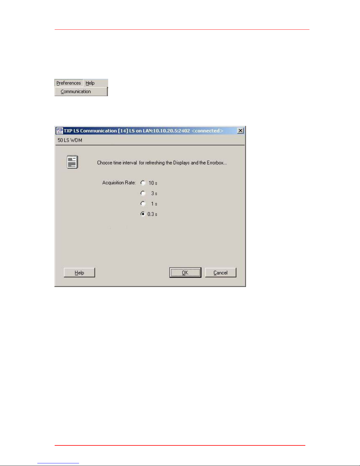
3.2.4 The ‘Preferences’ menu
The ‘preferences’ menu contains one item: ‘Communication’, which allows to define
the refreshing rate of all information retrieved from the card.
Depending on the bandwidth and reliability of your connection between TXP and PC,
you can select update rates from 10 seconds down to 0.3 s.


4.1 Troubleshooting
4 Service and Maintenance
4.1 Troubleshooting
Card does not work at all :
Look if the Card is inserted properly into the TXP mainframe and the ejector
handle has snapped into its position.
Look if the mainframe is powered up (does any LED light up)
You don’t get the desired laser output power
Is the global interlock closed (TXP5016 only)?
If you do not use the global interlock, put the short circuit plug delivered with the
TXP5016 on the D-SUB connector at the rear panel of the TXP.
If you don’t find the error source by means of the trouble shooting list, please contact
the Thorlabs Hotline (europe@thorlabs.com)
4.2 Recalibration
In normal operation the LS5000 card does not need any service. If highest precision
of the measurements is vital for you, you should send your module for recalibration to
Thorlabs GmbH (Germany) every two years. You can see the due date of calibration
in the card info-menu of the card driver (refer to 3.2.3, “The cards menu”).
LS5000 / page 23

5.1 Warranty
5 Appendix
5.1 Warranty
Thorlabs GmbH warrants material and production of the LS5000 for a period of 24
months starting with the date of shipment. During this warranty period Thorlabs
GmbH will see to defaults by repair or by exchange if these are entitled to warranty.
For warranty repairs or service the unit must be sent back to Thorlabs GmbH
(Germany) or to a place determined by Thorlabs GmbH . The customer will carry the
shipping costs to Thorlabs GmbH, in case of warranty repairs Thorlabs GmbH will
carry the shipping costs back to the customer.
If no warranty repair is applicable the customer also has to carry the costs for back
shipment.
In case of shipment from outside EU duties, taxes etc. which should arise have to be
carried by the customer.
Thorlabs GmbH warrants the hard- and software determined by Thorlabs GmbH for
this unit to operate fault-free provided that they are handled according to our
requirements. However, Thorlabs GmbH does not warrant a faulty free and
uninterrupted operation of the unit, of the soft- or firmware for special applications nor
this instruction manual to be error free. Thorlabs GmbH is not liable for consequen-
tial damages.
Restriction of warranty
The warranty mentioned before does not cover errors and defects being the result of
improper treatment, software or interface not supplied by us, modification, misuse or
operation outside the defined ambient conditions (refer also to the TXP5016 /
TXP5004 mainframe operation manual) stated by us or unauthorized maintenance.
Further claims will not be consented to and will not be acknowledged. Thorlabs
GmbH does explicitly not warrant the usability or the economical use for certain
cases of application.
Thorlabs GmbH reserves the right to change this instruction manual or the technical
data of the described unit at any time.
LS5000 / page 24

5.2 Thorlabs “End of Life” policy (WEEE)
5.2 Thorlabs “End of Life” policy (WEEE)
As required by the WEEE (Waste Electrical and Electronic Equipment Directive) of
the European Community and the corresponding national laws, Thorlabs offers all
end users in the EC the possibility to return “end of life” units without incurring
disposal charges.
This offer is valid for Thorlabs electrical and electronic equipment
• sold after August 13
th
2005
• marked correspondingly with the crossed out “wheelie bin” logo (see Figure 7)
• sold to a company or institute within the EC
• currently owned by a company or institute within the EC
• still complete, not disassembled and not contaminated
As the WEEE directive applies to self contained operational electrical and electronic
products, this “end of life” take back service does not refer to other Thorlabs
products, such as
• pure OEM products, that means assemblies to be built into a unit by the user
(e. g. OEM laser driver cards)
• components
• mechanics and optics
• left over parts of units disassembled by the user (PCB’s, housings etc.).
If you wish to return a Thorlabs unit for waste recovery, please contact Thorlabs or
your nearest dealer for further information.
5.2.1 Waste treatment on your own responsibility
If you do not return an “end of life” unit to Thorlabs, you must hand it to a company
specialized in waste recovery. Do not dispose of the unit in a litter bin or at a public
waste disposal site.
LS5000 / page 25

5.2 Thorlabs “End of Life” policy (WEEE)
5.2.2 Ecological background
It is well known that WEEE pollutes the environment by releasing toxic products
during decomposition. The aim of the European RoHS directive is to reduce the
content of toxic substances in electronic products in the future.
The intent of the WEEE directive is to enforce the recycling of WEEE. A controlled
recycling of end of life products will thereby avoid negative impacts on the
environment.
Figure 7 Crossed out “wheelie bin” symbol
LS5000 / page 26

5.3 List of Acronyms and abbreviations
5.3 List of Acronyms and abbreviations
The following acronyms and abbreviations are used in this manual:
ADC Analog to Digital Converter
APC Angled Physical Contact
ASCII American Standard Code for Information Interchange
CLR CLeaR
CR Carriage Return
DAC Digital to Analog Converter
D-Share Differential share
IEEE Institute for Electrical and Electronic Engineering
I-Share Integral share
LDC Laser Diode Controller
LED Light Emitting Diode
PC Personal Computer
PC Physical Contact
P-Share Proportional share
SDC Selected Device Clear
SEL SELect
SW Soft Ware
TEC ThermoElectric Cooler (Peltier Element)
LS5000 / page 27

5.4 List of figures
5.4 List of figures
Figure 1 LS5000 front view 9
Figure 2 The TXP Explorer Window 12
Figure 3 The LS5000 GUI Surface 13
Figure 4 Select the IP-Address 14
Figure 5 Select Portnumber and Timeout 14
Figure 6 The card selection window 15
Figure 7 Crossed out “wheelie bin” symbol 26
LS5000 / page 28

5.5 List of possible status messages
5.5 List of possible status messages
“Card Missing” This status message shows if you have
established a connection between the
corresponding software module and a card and
then remove the card from the TXP.
“Critical Card Temperature reached” The card temperature is too high. The laser will
probably be switched off. Please wait for
cooling down.
“Supply Voltage Failed”
Internal hardware error.
“Global Interlock Open”
Global Interlock has opened. Close it or use
the short circuit plug delivered with the TXP.
“Temperature not Stabilized”
Wait for the laser temperature to reach its
operating temperature.
“Laser Current Limit reached”
The laser current reached the user-set limit.
LS5000 / page 29

5.6 Certifications and compliances
5.6 Certifications and compliances
Certifications and compliances
Category Standards or description
EC
Declaration of
Conformity EMC
Meets intent of Directive 89/336/EEC for Electromagnetic Compatibility.
Compliance was demonstrated to the following specifications as listed in the
Official Journal of the European Communities:
EN 61326 EMC requirements for Class A electrical equipment
for measurement, control and laboratory use,
including Class A Radiated and Conducted
Emissions
1,2,3
and Immunity.
1,2,4
IEC 61000-4-2 Electrostatic Discharge Immunity (Performance
criterion A)
IEC 61000-4-3 Radiated RF Electromagnetic Field Immunity
(Performance criterion A)
IEC 61000-4-4 Electrical Fast Transient / Burst Immunity
(Performance criterion A)
IEC 61000-4-5 Power Line Surge Immunity (Performance criterion
A)
IEC 61000-4-6 Conducted RF Immunity (Performance criterion A)
IEC 61000-4-11 Voltage Dips and Interruptions Immunity
(Performance criterion A)
EN 61000-3-2 AC Power Line Harmonic Emissions
EN 61000-3-3 Voltage Fluctuations and Flicker
Australia /
New Zealand
Declaration of
Conformity EMC
Complies with the Radiocommunications Act and demonstrated per EMC Emission
standard
1,2,3
:
AS/NZS 2064 Industrial, Scientific, and Medical
Equipment: 1992
FCC EMC
Compliance
Emissions comply with the Class A Limits of FCC Code of Federal Regulations 47,
Part 15, Subpart B
1,2,3
.
1
Compliance demonstrated using high-quality shielded interface cables.
2
Compliance demonstrated with the LS5000 and ITC5xxx series modules installed in the Thorlabs
TXP5016 mainframe.
3
Emissions, which exceed the levels required by these standards, may occur when this equipment
is connected to a test object.
4
Minimum Immunity Test requirement.
LS5000 / page 30

5.6 Certifications and compliances
LS5000 / page 31
Certifications and compliances
Category Standards or description
Complies with EN60825-1/A2:2001 Safety of laser products Part 1.
Equipment classification,
requirements and user’s guide.
Class 1M
IEC60825-1/A2:2001 Safety of laser products Part 1.
Equipment classification,
requirements and user’s guide.
Class 1M
21CFR 1040.10
Laser Notice No. 50
Code of Federal Regulations,
Radiological Health, Part 1040 Performance Standards for LightEmitting Products. Class 1M

5.7 Copyright
5.7 Copyright
Thorlabs GmbH has taken every possible care in preparing this User Manual. We
however assume no liability for the content, completeness or quality of the
information contained therein. The content of this manual is regularly updated and
adapted to reflect the current status of the software. We furthermore do not
guarantee that this product will function without errors, even if the stated
specifications are adhered to.
Under no circumstances can we guarantee that a particular objective can be
achieved with the purchase of this product.
Insofar as permitted under statutory regulations, we assume no liability for direct
damage, indirect damage or damages suffered by third parties resulting from the
purchase of this product. In no event shall any liability exceed the purchase price of
the product.
Please note that the content of this User Manual is neither part of any previous or
existing agreement, promise, representation or legal relationship, nor an alteration or
amendment thereof. All obligations of Thorlabs GmbH result from the respective
contract of sale, which also includes the complete and exclusively applicable
warranty regulations. These contractual warranty regulations are neither extended
nor limited by the information contained in this User Manual. Should you require
further information on this product, or encounter specific problems that are not
discussed in sufficient detail in the User Manual, please contact your local Thorlabs
dealer or system installer.
All rights reserved. This manual may not be reproduced, transmitted or translated to
another language, either as a whole or in parts, without the prior written permission of
Thorlabs GmbH.
Status: 2009
© Thorlabs GmbH. All rights reserved.
LS5000 / page 32

5.8 Addresses
5.8 Addresses
Our Company is represented by several distributors and sales offices throughout the
world.
Europe
Thorlabs GmbH
Hans-Boeckler-Str. 6
D-85221 Dachau
Germany
Sales and Support
Phone: +49 (0) 81 31 / 5956-0
Fax: +49 (0) 81 31 / 5956-99
Email: europe@thorlabs.com
Web: www.thorlabs.com
USA
Thorlabs, Inc.
435 Route 206 North
Newton, NJ 07860
USA
Sales and Support
Phone: 1-973-579-7227
Fax: 1-973-300-3600
Email: sales@thorlabs.com
Email: techsupport@thorlabs.com
Web: www.thorlabs.com
LS5000 / page 33

5.8 Addresses
LS5000 / page 34
Japan
Thorlabs, Inc.
3-6-3, Kitamachi,
Nerima-ku, Tokyo 179-0081
Japan
Sales and Support
Phone: +81-3-6915-7701
Fax: +81-3-6915-7716
Email: sales@thorlabs.jp
Web: www.thorlabs.co.jp
Please call our hotlines, send an Email to ask for your nearest distributor or just visit
our homepage
http://www.thorlabs.com
 Loading...