


Operation Manual
Thorlabs Instrumentation
LED Illumination System for Fluorescence Lifetime Imaging
(FLIM)
LEDD3
2009

Version:
Date:
1.2
03.03.2009
© 2009 Thorlabs
© 2009 Thorlabs

Table of Contents
Foreword 3
Part I General Information
................................................................................................................................... 51 Safety
................................................................................................................................... 82 Ordering Codes and Accessories
Part II Getting Started
................................................................................................................................... 101 Unpacking
................................................................................................................................... 102 Preparation
................................................................................................................................... 113 Physical Overview
......................................................................................................................................................... 11Operating Elements on the Front Panel
......................................................................................................................................................... 12Operating Elements on the Rear Panel
......................................................................................................................................................... 12Operating Elements on the LED Head
Part III Operating the LEDD3
................................................................................................................................... 141 Operation and Settings
......................................................................................................................................................... 14Navigating the Menus
......................................................................................................................................................... 15Operation Modes
......................................................................................................................................................... 18Settings and Configuration
................................................................................................................................... 202 Remote Application
......................................................................................................................................................... 20Installation
......................................................................................................................................................... 28Operating the LEDD3 by the Remote Application
................................................................................................................................... 323 Changing the LED
5
10
14
Part IV Computer Interface
................................................................................................................................... 341 Connecting a Computer
................................................................................................................................... 342 LEDD3 Utility Software
................................................................................................................................... 353 Command Reference
......................................................................................................................................................... 35Command List
......................................................................................................................................................... 35Description
................................................................................................................................... 394 Status Reporting
Part V Maintenance and Repair
................................................................................................................................... 411 Maintenance
................................................................................................................................... 412 Firmware Update
................................................................................................................................... 413 Troubleshooting
Part VI Appendix
................................................................................................................................... 441 Warranty
................................................................................................................................... 452 Certifications and Compliances
................................................................................................................................... 473 Technical Data
......................................................................................................................................................... 47Common Data
......................................................................................................................................................... 47Technical Data
......................................................................................................................................................... 48LED for Frequency Domain FLIM
................................................................................................................................... 524 Thorlabs 'End of Life' Policy (WEEE)
......................................................................................................................................................... 52Waste Treatment on your own Responsibility
34
41
44
© 2009 Thorlabs

......................................................................................................................................................... 52Ecological Background
Part VII Listings
................................................................................................................................... 541 List of Acronyms
................................................................................................................................... 542 List of Figures
................................................................................................................................... 563 Addresses
Part VIII Application Note
................................................................................................................................... 581 Fluorescence Lifetime Imaging (FLIM)
......................................................................................................................................................... 58Time Domain FLIM
......................................................................................................................................................... 59Frequency Domain FLIM
Index 1
54
58
© 2009 Thorlabs

We aim to develop and produce the best solution for your application
in the field of optical measurement technique. To help us to come up
to your expectations and develop our products permanently we need
your ideas and suggestions. Therefore, please let us know about
possible criticism or ideas. We and our international partners are
looking forward to hearing from you.
Thorlabs GmbH
This part of the instruction manual contains every specific information on how
to handle and use the LEDD3 - FLIM LED Driver. A general description is
followed by explanations of how to operate the unit remotely via the USB
connection.
Attention
This manual contains "WARNINGS" and "ATTENTION" label in
this form, to indicate danger for persons or possible damage of
equipment.
Please read these advises carefully!
NOTE
This manual also contains "NOTES" and "HINTS" written in this form.
© 2009 Thorlabs

General Information
LEDD3 - FLIM LED Driver User
Manual
Part
I

5General Information
1
1.1
General Information
The LED modulating system (LEDD3 series) is designed for frequency domain
Fluorescence Lifetime Imaging (FLIM) and other microscopy applications that
require modulated high-power LED illumination sources.
The compact LED driver in the LEDD3 series can supply a high current (up to 1A) to
high-power LEDs. The LEDD3 series system includes an optical head, modulating
electronics, and a heat sink designed to dissipate the heat generated by high-power
LEDs. The design of the head allows the user to mount any compatible star-shaped
PCB packaged LED.
Please refer to chapter Fluorescence Lifetime Imaging for application notes.
Safety
GAttentionG
All statements regarding safety of operation and technical data in
this instruction manual will only apply when the unit is operated
correctly.
Before applying power to your LEDD3 system, make sure that the
protective conductor of the 3 conductor mains power cord is
correctly connected to the protective earth contact of the socket
outlet!
Improper grounding can cause electric shock with damages to
your health or even death!
The LEDD3 must not be operated in explosion endangered
environments!
The LED head, control inputs and outputs must only be
connected with duly shielded connection cables.
Only with written consent from Thorlabs may changes to single
components be carried out or components not supplied by
Thorlabs be used.
Do not obstruct the air ventilation slots in housing!
Do not remove covers!
Refer servicing to qualified personal!
© 2009 Thorlabs
This precision device is only dispatchable if duly packed into the
complete original packaging including the plastic form parts. If
necessary, ask for a replacement package.
Mobile telephones, cellular phones or other radio transmitters are
not to be used within the range of three meters of this unit since
6 LEDD3 - FLIM LED Driver User Manual
the electromagnetic field intensity may then exceed the maximum
allowed disturbance values according to IEC 61326-1.
This product has been tested and found to comply with the limits
according to IEC 61326-1 for using connection cables shorter than
3 meters (9.8 feet).
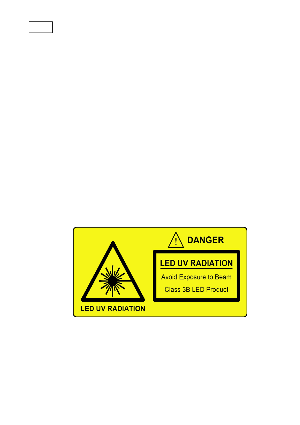
GCautionG
The head of LEDD3 can contain an UV light LED! In this case the
LED radiates intense UV light during operation. Precautions must
be taken to prevent looking directly at the UV light with
unprotected eyes.
Do not look directly into the UV light or look through the optical
system during operation of the device. This can be harmful to the
eyes even for brief periods due to the high intensity of the UV light.
If there is the possibility to receive a reflection of the UV light, UV
light protective glasses have to be used to prevent that UV light
can catch one's eye directly.
If viewing the UV light is necessary, use UV light protective
glasses to avoid damage by the UV light.
GCautionG
The head of the LEDD3 is also a heat sink for the LED and will be
heated up to more than 50°C!
© 2009 Thorlabs

GAttentionG
The following statement applies to the products covered in this
manual, unless otherwise specified herein. The statement for other
products will appear in the accompanying documentation.
Note: This equipment has been tested and found to comply with
the limits for a Class B digital device, pursuant to Part 15 of the
FCC Rules and meets all requirements of the Canadian
Interference-Causing Equipment Standard ICES-003 for digital
apparatus. These limits are designed to provide reasonable
protection against harmful interference in a residential installation.
This equipment generates, uses, and can radiate radio frequency
energy and, if not installed and used in accordance with the
instructions, may cause harmful interference to radio
communications. However, there is no guarantee that interference
will not occur in a particular installation. If this equipment does
cause harmful interference to radio or television reception, which
can be determined by turning the equipment off and on, the user is
encouraged to try to correct the interference by one or more of the
following measures:
7General Information
· Reorient or relocate the receiving antenna.
· Increase the separation between the equipment and receiver.
· Connect the equipment into an outlet on a circuit different from
that to which the receiver is connected.
· Consult the dealer or an experienced radio/T.V. technician for
help.
Thorlabs GmbH is not responsible for any radio television
interference caused by modifications of this equipment or the
substitution or attachment of connecting cables and equipment
other than those specified by Thorlabs GmbH. The correction of
interference caused by such unauthorized modification,
substitution or attachment will be the responsibility of the user.
The use of shielded I/O cables is required when connecting this
equipment to any and all optional peripheral or host devices.
Failure to do so may violate FCC and ICES rules.
© 2009 Thorlabs

8 LEDD3 - FLIM LED Driver User Manual
1.2
Ordering Codes and Accessories
Ordering code Short description
LEDD3-365 LEDD3 - FLIM LED Driver with LED Head @ 365nm
LEDD3-405 LEDD3 - FLIM LED Driver with LED Head @ 405nm
LEDD3-470 LEDD3 - FLIM LED Driver with LED Head @ 470nm
LEDD3-630 LEDD3 - FLIM LED Driver with LED Head @ 630nm
Other wavelength on request ranging from 365nm up to 940nm.
Please visit our homepage http://www.thorlabs.com for further information.
© 2009 Thorlabs

Getting Started
LEDD3 - FLIM LED Driver User
Manual
Part
II

10 LEDD3 - FLIM LED Driver User Manual
2
2.1
2.2
Getting Started
Unpacking
Inspect the packaging for damage.
If the shipping container seems to be damaged, keep it until you have inspected the
contents and you have inspected the LEDD3 mechanically and electrically.
Verify that you have received the following items:
1. 1 LEDD3 (main unit and LED head)
2. 1 Power cord, connector according to ordering country
3. 1 Power supply 12V / 3.75A
4. 1 USB cable
5. 1 Operation manual
6. 1 Applications and driver CD
Preparation
1.Connect LED head cable with socket labeled "LED" at the back of the main
control unit, see figure 1
2.Connect power supply cable with main control unit, use only the power supply
supplied with your LEDD3 unit
3.Plug in power supply
Figure 1 Connecting the LED Head
GAttentionG
Prior to switching on your LEDD3 please check if the line voltage
corresponds to the input voltage range of the power supply!
Turn the unit on by pressing the power switch on the rear side of the unit.
After the device is powered up, the graphics display will show a 'Welcome' screen
© 2009 Thorlabs

for a few seconds.
The LEDD3 is immediately ready to use after turning on. The rated accuracy is
reached, however, after a warming-up period of approximately 10 minutes.
11Getting Started
2.3
2.3.1
Physical Overview
Operating Elements on the Front Panel
© 2009 Thorlabs
Figure 2 Display and Operating Elements on the Front Panel
12 LEDD3 - FLIM LED Driver User Manual
2.3.2
Operating Elements on the Rear Panel
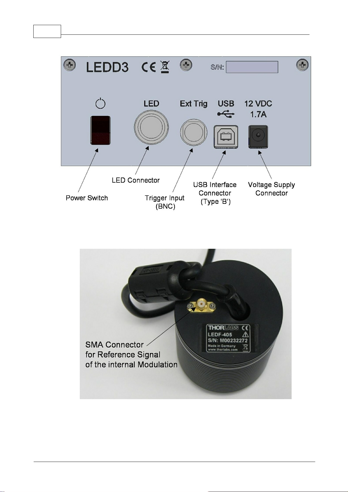
2.3.3
Figure 3 Operating Elements on the Rear Panel
Operating Elements on the LED Head
Figure 3a Operating Elements on the LED Head
© 2009 Thorlabs

Operating the LEDD3
LEDD3 - FLIM LED Driver User
Manual
Part
III

14 LEDD3 - FLIM LED Driver User Manual
3
3.1
3.1.1
Operating the LEDD3
The LEDD3 can either be controlled via the front panel of the main unit (see chapter
Operation and Settings) or by a remote application (see chapter Remote
Application).
Operation and Settings
The following sub chapters contain the description about the operation of the
LEDD3.
Navigating the Menus
The LEDD3 is controlled by three buttons and the multi-control knob on the front
panel. The two buttons below the graphics display have an Enter and Escape
functionality. The button with LED indicator is used to switch the LED on or off. The
multi-control is used to select the desired menu or to change the settings.
After switching on the LEDD3 a 'Welcome' screen appears for a few seconds.
Figure 4 Welcome Screen
In case no LED head is connected you will be prompted to switch off the main unit,
connect the LED head and switch on the device.
The display will show the screen of one of the 3 LED operation modes (Constant
Current, Internal Modulation or External Control Mode). The 'Main Menu' can be
accessed via the 'ESC' button.
Figure 5 Main Menu
To select an operation mode or a configuration display the multi-control knob is
used. Press the 'Ok' button to enter the selected item.
© 2009 Thorlabs

15Operating the LEDD3
3.1.2
Operation Modes
Only if one of the three operation modes (Constant Current, Internal Modulation or
External Control) is selected the LED can be enabled /switched on.
It is possible to leave the active mode when the LED is switched on and enter the
main menu. However, the LED has to switch off before you can enter another
operation mode. This can be done while the main menu is selected by pressing the
LED button.
Constant Current Mode
The 'Constant Current Mode' provides a constant non-modulated LED current. The
current can be set directly with the multi-control knob. No confirmation is necessary.
The 'Ok' button has no functionality within this mode. The LED is switched on or off
with the LED button. The LED current can be changed when the LED is off as well as
when it is in operation. This allows to increase or reduce the brightness of the LED.
The current limit is displayed at the bottom of the screen.
Return to the main menu with the 'ESC' button.
Figure 6 Constant Current Mode
Internal Modulation Mode
This mode can be used to apply a sine wave modulation to the LED with a defined
frequency.
The 'Internal Modulation Mode' features three settings: current, frequency and
modulation depth. The first parameter is the DC component. The frequency can be
set between 10MHz and 100MHz in steps of 0.1MHz. The modulation depth
describes the relation between constant and variable component.
Figure 7 Internal Modulation Mode
To change the settings select one of the parameters using the multi-control knob and
press the 'Ok' button. The corresponding screen appears and the value for the
current, the frequency or the modulation depth can be adjusted with the multi-control
© 2009 Thorlabs

16 LEDD3 - FLIM LED Driver User Manual
knob. Changing the value will take effect immediately. However, since the editing
mode is active the value has to be confirmed with the 'Ok' button or can be canceled
with the 'ESC' button.
Figure 8 Internal Modulation - Current Adjustment
Figure 9 Internal Modulation - Frequency Adjustment
Figure 10 Internal Modulation - Modulation Depth Adjustment
See the chapter Technical Data for information about cut-off frequencies for certain
LEDs.
The following diagram illustrates the definition of current and modulation depth:
© 2009 Thorlabs

17Operating the LEDD3
Figure 11 Definition of the Parameter Current and Modulation Depth
External Control Mode
This mode allows to control the LEDD3 by an external signal.
The 'External Control Mode' has no parameter settings. The LED can only be
controlled via the BNC connector at the rear panel of the LEDD3. The applied
voltage corresponds to the LED current. 1V is equivalent to a LED current of
100mA. A maximum voltage of 10V can be applied, which results in a current of
1000mA.
Please note: The maximum current is limited by the user defined current limit set in
the 'Adjust Limit' menu.
Figure 12 External Control Mode
The Modulation Frequency range is 0 to 100kHz and valid for sine wave modulation.
The last selected operation mode will be saved. After switching on the LEDD3 again
this operation mode will be automatically the active mode. All settings are saved and
validated after a shut off. The current settings in the 'Constant Current Mode' and in
© 2009 Thorlabs

18 LEDD3 - FLIM LED Driver User Manual
the 'Internal Modulation Mode' are two separate parameters and will be handled
individually.
3.1.3
Settings and Configuration
There are settings and system configurations, which can be accessed via the main
menu. To enter the main menu from one of the operation modes press the 'ESC'
button.
Figure 13 Main Menu
Select an item with the multi-control knob and press the 'Ok' button to access the
desired setting or configuration panel.
User Limit
The current limit can be changed by selecting 'User Limit'. The following screen
appears and the LED current limit can be set using the multi-control knob. The new
value has to be confirmed with the 'Ok' button or canceled with the 'ESC' button. The
LED current limit can be set up to the maximum LED current limit (LED Imax), which
is defined in the EEPROM of the LED head. See next section for more information.
Figure 14 LED Current Limit Setting
LED Configuration
In case a new LED was installed the LEDs maximum current and frequency need to
be configured. These values are saved in the EEPROM of the LED head and can be
changed in the 'LED Configuration' menu.
This menu entry is hidden in normal operation mode. Go to the 'User Limit' screen
described above and hold the "LED" button for about three seconds.
A sub menu appears and the LEDs maximum current (LED Imax) and frequency
(LED fmax) can be set. Press the 'Ok' button to select one of these limits. The multicontrol knob is used to change the value and has to be confirmed with the 'Ok' button
or canceled with the 'ESC' button.
© 2009 Thorlabs

Figure 15a LED Maximum Current
19Operating the LEDD3
Figure 15b LED Maximum Frequency
GAttentionG
A wrong and too high LED maximum current limit can cause damage to the
LED. Prior to changing the LED maximum current limit of the LED head
check if the LED can handle this current!
System Settings
Within the system configuration the LCD backlight brightness can be set. Select
'Configuration' from the main menu via the multi-control knob and press 'Ok'. A sub
menu appears and the 'Brightness' setting can be accessed by pressing the 'Ok'
button. The multi-control knob is used to change the brightness of the LCD backlight
between 0 and 100%. Confirm your setting with 'Ok' or cancel it with 'ESC'.
© 2009 Thorlabs
Figure 16 LCD Backlight Brightness Setting

20 LEDD3 - FLIM LED Driver User Manual
About
The item 'About' gives information about the firmware version and serial number of
the LEDD3 and the connected LED head.
Figure 17 About Panel
3.2
3.2.1
3.2.1.1
Remote Application
The LEDD3 remote software can be used to operate the LEDD3 - FLIM LED Driver
via the PC. The device has to be connected to the PC by an USB cable.
Installation
The Installation Menu
Before installing the LEDD3 remote application, please make sure that no Thorlabs
LEDD3 - FLIM LED Driver is connected. After you inserted the LEDD3 installation
CD an autorun menu will appear. If autorun is disabled on your system please
browse the installation CD and run "CD-Drive:\Autorun\Autorun.exe".
Figure 18 Autorun Menu
© 2009 Thorlabs

Note: Please be aware that you need a VISA engine installed on your system to
operate the LEDD3 remote application .
21Operating the LEDD3
3.2.1.2
Installing VISA Runtime Engine
A VISA runtime 4.3.0 or higher has to be installed on your system to operate the
LEDD3 remote application.
You may install the National Instruments©® VISA runtime engine provided on the
installation CD. You may also download the latest NI-VISA runtime engine from the
National Instruments©® web site (www.ni.com/visa).
In case you want to use the VISA engine provided on the installation CD select "NIVISA Engine". An installation wizard will be started. If you are running Windows
VISTA©® you might be prompted to change to the "elevated mode". Please ask
your administrator for help when you do not have administrator privileges.
Press "Next" to continue.
Now you have to specify an installation path. Press "Next" to continue.
© 2009 Thorlabs
Figure 19 VISA Installation Start Screen

22 LEDD3 - FLIM LED Driver User Manual
Figure 20 Selection of the Installation Path
Select "I accept the License Agreement(s)" if you do so and press "Next".
Figure 21 License Agreement
In the next window please select the features to install. To operate the LEDD3
remote application you need at least the USB and the Serial feature (see figure 22).
Confirm with "Next" to start installation.
© 2009 Thorlabs

Figure 22 Selection of VISA Features
23Operating the LEDD3
After all files are copied and the installation was successful you might be prompted
to reboot your machine. Click "Finish" to finalize the installation.
Figure 23 Finalize Installation
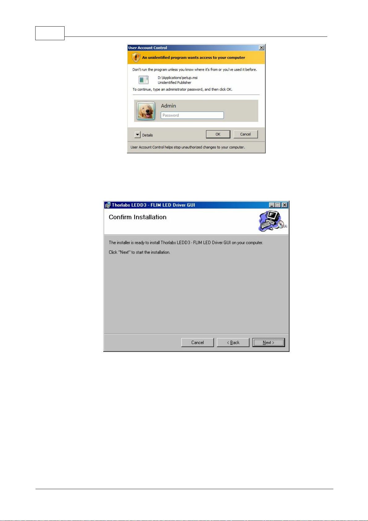
3.2.1.3
Installing the Remote Application
Select "LEDD3 - Application software" from the installation menu to start the
installation wizard. If you are running Windows VISTA©® you might be promted to
change to the "elevated mode", as shown in figure 24. Please ask your administrator
for help when you do not have administrator privileges.
© 2009 Thorlabs
24 LEDD3 - FLIM LED Driver User Manual
Figure 24 Request for Administrator Privileges
After the LEDD3 remote application installation wizard finished the initialization you
will be prompted to specify the installation path. Confirm with "Next" when you
selected the installation path of your choice.
Figure 25 Selecting the Installation Paths
During the installation process a separate installation wizard will start to register the
device drivers on your system.
© 2009 Thorlabs

Figure 26 The Device Driver Installer
Please press 'Next >' and follow this wizard. You will be asked two times to
"Continue anyway" the installation. Please do so.
25Operating the LEDD3
After installation was successful you will see a window containing some information
about the installed drivers. Press "Finish" to close the wizard.
© 2009 Thorlabs
Figure 27 The Windows Logo Test

26 LEDD3 - FLIM LED Driver User Manual
Figure 28 Additional Notes
Press "Close" to finish the installation of the LEDD3 remote application.
3.2.1.4
Figure 29 Installation successful
Driver Installation
The necessary drivers for the LEDD3 - FLIM LED Driver is automatically copied to
the system folder during the installation of the LEDD3 remote application.
Attention:
The following procedure will only be necessary for Windows XP/2000©®.
On the first connection of a device the "Found New Hardware Wizard" will start to
install the new device. Depending on the configuration of your system you might be
asked if you want to connect to "Windows Update to search for software" shown in
© 2009 Thorlabs

figure 30. Please select "No, not this time" and click "Next" to continue.
Figure 30 The Found New Hardware Wizard
27Operating the LEDD3
Select "Install the software automatically" and click "Next" to continue.
Figure 31 Choosing the Installation Mode
Finalize the installation by clicking "Finish".
© 2009 Thorlabs

28 LEDD3 - FLIM LED Driver User Manual
Figure 32 Finishing the New Found Hardware Wizard
3.2.2
3.2.2.1
Operating the LEDD3 by the Remote Application
The LEDD3 remote application can be used to operate a LEDD3 - FLIM LED Driver
via the PC.
Every setting made will automatically be used by the device. The parameters are
updated/synchronized once every second.
Connecting a Device
Please connect the LEDD3 to your PC with the shipped USB cable. The USB
socket labeled "USB" at the back of the main control.
After starting the application the following window is displayed.
Figure 33 The Start Screen
Use the green button or the menu option 'Connect...' to open the device selection
dialog.
© 2009 Thorlabs

29Operating the LEDD3
Figure 34 The Device Selection Dialog
Select your LEDD3 - FLIM LED Driver by double-clicking or pressing the "Accept"
button. The device will be connected and the last active mode will be entered. The
upload of the actual values on the system may take some seconds.
3.2.2.2
Constant Current Mode
The constant current can be selected by pressing the 'Constant Current Mode' button
(see figure 35) or the corresponding menu entry 'Mode/Constant Current Mode'.
You can either change the value directly by typing into the numeric control, or use the
small arrows. The maximum value depends on the user current limit, which is set in
the configuration menu.
Figure 35 Constant Current Mode
3.2.2.3
Internal Modulation Mode
The internal modulation mode can be selected by pressing the 'Internal Modulation
Mode' button (see figure 36) or the corresponding menu entry 'Mode/Internal
Modulation Mode'.
You can either change the values directly by typing into the numeric controls, or use
the arrow controls.
The maximum user frequency is stored in the LED head and is specific to the
mounted LED.
The maximum current is half of the user current limit, which is set in the configuration
menu.
© 2009 Thorlabs

30 LEDD3 - FLIM LED Driver User Manual
Figure 36 The Internal Modulation Mode
3.2.2.4
External Control Mode
The 'External Control Mode' can be selected by pressing the 'External Control Mode'
button (see figure 37) or the corresponding menu entry 'Mode/External Control
Mode'.
This screen is for information purposes only and offers no user inputs.
In this mode the LED can only be controlled via the BNC connector at the rear panel
of the LEDD3. The applied voltage corresponds to the LED current. 1V is equivalent
to a LED current of 100mA. A maximum voltage of 10V can be applied, which will
result in a current of 1A.
Figure 37 The External Control Mode
© 2009 Thorlabs

31Operating the LEDD3
3.2.2.5
User Limit Current
The user can set an individual current limit, which must be below the LEDs maximum
current limit stored in the LED head.
Figure 38 User Limit
3.2.2.6
Figure 39 User Limit Dialog
Configuring a new LED
The LEDD3 - FLIM LED Driver offers the possibility to operate a LED of your
choice.
Use the menu 'Configuration/LED Configuration' to set the new LEDs maximum
current and frequency.
© 2009 Thorlabs
Figure 40 LED Configuration Menu

32 LEDD3 - FLIM LED Driver User Manual
Figure 41 LED Maximum Limit
Figure 42 LED Maximum Frequency
3.3
Changing the LED
The LEDD3 - FLIM LED Driver offers the possibility to operate a LED of your
choice.
Contact Thorlabs for more information!
© 2009 Thorlabs

Computer Interface
LEDD3 - FLIM LED Driver User
Manual
Part
IV

34 LEDD3 - FLIM LED Driver User Manual
4
4.1
Computer Interface
The LEDD3 has a USB 2.0 interface that allows to send commands from a host
computer to the instrument using the LEDD3 - VISA Instrument Driver. The
connection between PC and LEDD3 is accomplished by an USB cable with a male
type 'A' connector at the PC side and a type 'B' connector on the instrument side.
See chapter Command List for a complete command reference.
Connecting a Computer
GAttentionG
To successfully complete the installation of the LEDD3 USB driver, you must
have Administrator privileges on the PC, on which you are performing the
installation.
Prior to connecting the LEDD3 with the PC, please insert the CD that was shipped
with the instrument and install the LEDD3 drivers. When the following message
appears after the installation you have to install NI-VISA from the distribution CD or
from the National Instruments web site, too.
4.2
Figure 43 No VISA Engine installed
After successfully installing the software connect the LEDD3 to a USB port of your
PC. The PC will find sequentially a LEDD3 and a DFU device. Please follow the
instructions of the dialog screens and allow the installation.
LEDD3 Utility Software
The LEDD3 comes with an utility software, by which the LEDD3 can be remotely
operated.
Additionally the LEDD3 comes with a driver software, which can be used by C/C++/
LabVIEW and every programming language supporting DLLs.
Please refer to the manuals, which are copied on your system when installing the
device driver.
Note: Please be aware that you need a VISA engine installed on your system to use
the LEDD3 - VISA Instrument Driver.
© 2009 Thorlabs

35Computer Interface
Command
Description
LEDD3_setLimitCurrent
Set User Current Limit
LEDD3_getLimitCurrent
Get User Current Limit
LEDD3_setMaxLimit
Set Maximum Current Limit
LEDD3_getMaxLimit
Get Maximum Current Limit
LEDD3_setMaxFrequency
Set Maximum Frequency
LEDD3_getMaxFrequency
Get Maximum Frequency
LEDD3_setOperationMode
Set Operation Mode
LEDD3_getOperationMode
Get Operation Mode
LEDD3_setLedOnOff
Set LED OnOff
LEDD3_getLedOnOff
Get LED OnOff
LEDD3_setModuCurrent
Set Internal Modulation Current
LEDD3_getModuCurrent
Get Internal Modulation Current
LEDD3_setModuFreq
Set Internal Modulation Frequency
LEDD3_getModuFreq
Get Internal Modulation Frequency
LEDD3_setModuDepth
Set Internal Modulation Depth
LEDD3_getModuDepth
Get Internal Modulation Depth
LEDD3_setConstCurrent
Set Constant Current
LEDD3_getConstCurrent
Get Constant Current
LEDD3_setDispBright
Set Display Brightness
LEDD3_getDispBright
Get Display Brightness
LEDD3_getStatusRegister
Get Status Register
LEDD3_errorMessage
Error Message
LEDD3_identificationQuery
Identification Query
LEDD3_revisionQuery
Revision Query
4.3
4.3.1
Command Reference
Command List
4.3.2
4.3.2.1
4.3.2.2
4.3.2.3
Description
Set User Limit Current
Command: LEDD3_setLimitCurrent
Parameter: Current limit in Ampere
Response: None
Description: Sets the current limit. This limit may not exceed the LEDs limit
specified in the LED head.
Get User Limit Current
Command: LEDD3_getLimitCurrent
Parameter: None
Response: Current limit in Ampere
Description: Returns the current limit.
Set Maximum Current Limit
Command: LEDD3_setMaxLimit
Parameter: Maximum current limit in ampere
Response: None
Description: Sets the LEDs maximum current limit in ampere. This limit
should only be set in case a new LED was installed.
© 2009 Thorlabs

36 LEDD3 - FLIM LED Driver User Manual
4.3.2.4
4.3.2.5
4.3.2.6
4.3.2.7
Get Maximum Current Limit
Command: LEDD3_getMaxLimit
Parameter: None
Response: Maximum current limit in ampere
Description: Returns the current limit.
Set Maximum Frequency
Command: LEDD3_setMaxFrequency
Parameter: Maximum frequency in MHz
Response: None
Description: Sets the maximum frequency in MHz. This limit should only be
set in case a new LED was installed.
Get Maximum Frequency
Command: LEDD3_getMaxFrequency
Parameter: None
Response: Maximum frequency in MHz
Description: Returns the LEDs maximum frequency.
Set Operation Mode
4.3.2.8
4.3.2.9
4.3.2.10
Command: LEDD3_setOperationMode
Parameter: Operation Mode
Response: None
Description: Sets the operation mode.
Get Operation Mode
Command: LEDD3_getOperationMode
Parameter: None
Response: Actual operation mode
Description: Returns the operation mode.
Set LED OnOff
Command: LEDD3_setLedOnOff
Parameter: LED output state
Response: None
Description: Sets the LED output.
Get LED OnOff
Command: LEDD3_getLedOnOff
Parameter: None
Response: LED output state
Description: Returns the LED output state.
4.3.2.11
Set Internal Modulation Current
Command: LEDD3_setModuCurrent
Parameter: Internal modulation current in Ampere
Response: None
© 2009 Thorlabs

Description: Sets the current used for internal modulation.
37Computer Interface
4.3.2.12
4.3.2.13
4.3.2.14
4.3.2.15
Get Internal Modulation Current
Command: LEDD3_getModuCurrent
Parameter: None
Response: Internal modulation current in Ampere
Description: Returns the current used for internal modulation in ampere.
Set Internal Modulation Frequency
Command: LEDD3_setModuFreq
Parameter: Frequency in MHz
Response: None
Description: Sets the internal modulation frequency in MHz.
Get Internal Modulation Frequency
Command: LEDD3_getModuFreq
Parameter: None
Response: Frequency in MHz
Description: Returns the internal modulation frequency.
Set Internal Modulation Depth
Command: LEDD3_setModuDepth
Parameter: Modulation depth in percent
Response: None
Description: Sets the internal modulation depth in percent.
4.3.2.16
4.3.2.17
4.3.2.18
Get Internal Modulation Depth
Command: LEDD3_getModuDepth
Parameter: None
Response: Modulation depth in percent
Description: Returns the internal modulation depth in percent.
Set Constant Current
Command: LEDD3_setConstCurrent
Parameter: Constant current in Ampere
Response: None
Description: Sets the current in ampere used for the constant current mode.
Get Constant Current
Command: LEDD3_getConstCurrent
Parameter: None
Response: Constant current in ampere
Description: Returns the current in Ampere used for the constant current
mode.
© 2009 Thorlabs

38 LEDD3 - FLIM LED Driver User Manual
4.3.2.19
4.3.2.20
4.3.2.21
4.3.2.22
Set Display Brightness
Command: LEDD3_setDispBright
Parameter: Display brightness in percent
Response: None
Description: Sets the display brightness.
Get Display Brightness
Command: LEDD3_getDispBright
Parameter: None
Response: Display brightness in percent
Description: Returns the display brightness.
Get Status Register
Command: LEDD3_getStatusRegister
Parameter: None
Response: Status register value
Description: Reads the content of the instruments status register. Refer to
chapter Status Reporting.
Error Message
4.3.2.23
4.3.2.24
Command: LEDD3_errorMessage
Parameter: Error code
Response: User readable message string
Description: This function takes the error code returned by the instrument
driver functions, interprets it and returns it as a user readable
string.
Identification Query
Command: LEDD3_identificationQuery
Parameter: None
Response: Manufacturer name
Device name
Serial number
Firmware revision
Description: This function returns the device identification information.
Revision Query
Command: LEDD3_revisionQuery
Parameter: None
Response: Instrument driver revision
Firmware revision
Description: This function returns the instruments driver revision and the
devices firmware revision.
© 2009 Thorlabs

39Computer Interface
Status
Bit
Name
Description
Bit 0
No LED Changed
The bit 'No LED' has changed.
Bit 1
No LED
The LED head is not connected to the chassis.
Bit 2
VCC Fail Changed
The bit 'VCC Fail' has changed.
Bit 3
VCC Fail
The power supply is out of range.
Bit 4
OTP Change
The bit 'OTP' (Over Temperature) has
changed.
Bit 5
OTP
Over temperature (OTP) in the chassis was
detected. The LED head was switched off.
Bit 6
LED Open Changed
The bit 'LED Open' has changed.
Bit 7
LED OPEN
The LED head is connected but no LED was
installed.
Bit 8
Limit Changed
The bit 'Limit' has changed.
Bit 9
Limit
The adjusted current is greater than the current
limit and was coerced to the limit.
Bit 10
OTP Head Changed
The bit 'OTP Head' (Over Temperature Head)
has changed.
Bit 11
OTP Head
Over temperature in the LED head was
detected. The LED head was switched off.
Bit 12
Interface Refresh
The user has changed settings.
4.4
Status Reporting
The LEDD3 stores the status in a register. It can be accessed via the
'LEDD3_getStatusRegister. The following table lists all status numbers and the
according descriptive messages. Each bit represents an error.
© 2009 Thorlabs

Maintenance and Repair
LEDD3 - FLIM LED Driver User
Manual
Part
V

41Maintenance and Repair
5
5.1
Maintenance and Repair
Maintenance
Protect the LEDD3 from adverse weather conditions. The LEDD3 is not water
resistant.
G Attention G
To avoid damage to the LEDD3, do not expose it to spray, liquids or
solvents!
The unit does not need a regular maintenance by the user.
If necessary the unit and the display can be cleaned with a cloth dampened with
water.
The LEDD3 does not contain any modules that could be repaired by the user
himself. If a malfunction occurs, the whole unit has to be sent back to Thorlabs. Do
not remove covers!
5.2
5.3
Firmware Update
Firmware upgrades can be done by the user via the USB interface.
You need the batch file LEDD3_Firmware_Update.bat and the hex file LEDD3.hex.
Both files have to be in the same directory.
Connect the LEDD3 with a USB cable to your computer. Check the COM port of the
LEDD3. It has to be COM1, COM2, COM3 or COM4. If not please change the COM
port to one of the listed COM ports.
Before you switch on the LEDD3 press the LED button and keep it pressed while
you switch on the device. The LEDD3 shows 'LEDD3 BOOTLOADER' in its display.
Start the batch file. The new firmware will be uploaded to the LEDD3.
Please refer to www.thorlabs.com for the latest LEDD3 firmware version that can be
downloaded as a *.hex file.
Do not switch off the LEDD3 or disconnect the USB cable during the firmware
download.
Troubleshooting
In case that your LEDD3 shows malfunction please check the following items:
· Unit does not work at all (no data is shown on the display):
© 2009 Thorlabs
· Is the power supply of the LEDD3 connected properly to the mains?
- Check the mains cable of the power supply.
· Is the LEDD3 turned on?

42 LEDD3 - FLIM LED Driver User Manual
- Turn on your LEDD3.
· Is the power supply connected properly to the LEDD3?
- Check the low voltage line of the power supply.
· LED cannot be switched on:
· Is on of the three operation modes (Constant Current, Internal Modulation or
External Control) selected?
- An operation mode can be selected from the main menu using the multifunction knob and pressing the 'Ok' button.
© 2009 Thorlabs

Appendix
LEDD3 - FLIM LED Driver User
Manual
Part
VI

44 LEDD3 - FLIM LED Driver User Manual
6
6.1
Appendix
Warranty
Thorlabs GmbH warrants material and production of the LEDD3 for a period of 24
months starting with the date of shipment. During this warranty period Thorlabs
GmbH will see to defaults by repair or by exchange if these are entitled to warranty.
For warranty repairs or service the unit must be sent back to Thorlabs GmbH
(Germany) or to a place determined by Thorlabs GmbH . The customer will carry
the shipping costs to Thorlabs GmbH, in case of warranty repairs Thorlabs GmbH
will carry the shipping costs back to the customer.
If no warranty repair is applicable the customer also has to carry the costs for back
shipment.
In case of shipment from outside EU duties, taxes etc. which should arise have to be
carried by the customer.
Thorlabs GmbH warrants the hard- and software determined by Thorlabs GmbH for
this unit to operate fault-free provided that they are handled according to our
requirements. However, Thorlabs GmbH does not warrant a faulty free and
uninterrupted operation of the unit, of the soft- or firmware for special applications
nor this instruction manual to be error free. Thorlabs GmbH is not liable for
consequential damages.
Restriction of warranty
The warranty mentioned before does not cover errors and defects being the result of
improper treatment, software or interface not supplied by us, modification, misuse or
operation outside the defined ambient conditions stated by us or unauthorized
maintenance.
Further claims will not be consented to and will not be acknowledged. Thorlabs
GmbH does explicitly not warrant the usability or the economical use for certain
cases of application.
Thorlabs GmbH reserves the right to change this instruction manual or the technical
data of the described unit at any time and without notice.
© 2009 Thorlabs

45Appendix
Certifications and Compliances
Category
Standards or description
EC
Declaration
of
Conformity EMC
Meets intent of Directive 89/336/EEC for Electromagnetic
Compatibility. Compliance was demonstrated to the following
specifications as listed in the Official Journal of the European
Communities:
EN 61326:1997
+A1:1998
+A2:2001
+A3:2003
Electrical equipment for measurement, control and
laboratory use – EMC requirements:
Immunity: complies with immunity test requirements
for equipment intended for use in industrial
locations
1
.
Emission: complies with EN 55011 Class B Limits
1,3
,
IEC 610003-2 and IEC 61000-3-3.
IEC 61000-4-2
Electrostatic Discharge Immunity (Performance
criterion C)
IEC 61000-4-3
Radiated RF Electromagnetic Field Immunity
(Performance Criterion A)
5
IEC 61000-4-4
Electrical Fast Transient / Burst Immunity (Perf.
Criterion C)
IEC 61000-4-5
Power Line Surge Immunity (Performance Criterion
A)
IEC 61000-4-6
Conducted RF Immunity (Performance Criterion A)
IEC 61000-411
Voltage Dips, Short Interruptions and Voltage
Variations Immunity (Performance Criterion A / C 6)
FCC EMC
Compliance
Emissions comply with the Class B Limits of FCC Code of Federal
Regulations 47, Part 15, Subpart B
1,3
.
EC
Declaration
of
Conformity Low Voltage
Compliance was demonstrated to the following specification as listed
in the Official Journal of the European Communities:
Low Voltage Directive 73/23/EEC, amended by 93/68/EEC
EN 61010-1:2001
Safety requirements for electrical equipment for
measurement, control and laboratory use.
U.S.
Nationally
Recognized
Testing
Laboratory
Listing
UL 61010-1 2
nd
ed.
Safety requirements for electrical equipment for
measurement, control, and laboratory use.
ISA-82:02.01
Safety requirements for electrical equipment for
measurement, control, and laboratory use.
Canadian
Certification
CAN/CSA C22.2
No. 61010-1-04
Safety requirements for electrical equipment for
measurement, control, and laboratory use.
Additional
Compliance
IEC 610101:2001
Safety requirements for electrical equipment for
measurement, control, and laboratory use.
Equipment
Type
Test and measuring
Safety
Class
Class I equipment (as defined in IEC 60950-1:2001)
1
Compliance demonstrated using high-quality shielded interface cables shorter
than 3 meters.
6.2
Certifications and Compliances
© 2009 Thorlabs

46 LEDD3 - FLIM LED Driver User Manual
3
Emissions, which exceed the levels required by these standards, may occur when
this equipment is connected to a test object.
5
MOD IN port capped at IEC 61000-4-3 test.
6
Performance Criterion C was reached at additional test levels according to EN
61326-1:2006 table 2
© 2009 Thorlabs

47Appendix
Line Voltage (Ext. Power Supply)
100 ... 240VAC (-10%, +10%)
Line Frequency (Ext. Power Supply)
50 ... 60Hz
Power Consumption (max)
20VA
Supply mains over Voltage
Category II (Cat II)
Input Voltage (LEDD3 chassis)
12VDC
Operating Temperature
1)
0 ... +40 °C
Storage Temperature
-40 ... +70 °C
Relative Humidity
Max. 80% up to 31 °C
decreasing to 50% at 40 °C
Pollution Degree (indoor use only)
2
Operation Altitude
< 3000 m
Warm-up Time for rated Accuracy
10 min
Weight
< 1 kg
Dimensions (W x H x D) without
operating elements
160 x 80 x 150 mm³
Dimensions (W x H x D) with
operating elements
160 x 80 x 168 mm³
LED Current Range
0 ... 1000mA
Modulation Frequency Range
(Internal Modulation Mode only)
10 ... 100MHz
Modulation
(Internal Modulation Mode only)
Sine Wave
Modulation Depth
1)
(Internal Modulation Mode only)
0 ... 100%
Trigger Output
(Internal Modulation Mode only)
Sine Wave
Modulation Frequency Range
(External Control Mode only)
0 ...100kHz
(Sine Wave)
Modulation
(External Control Mode only)
Arbitrary
Trigger Input
(External Control Mode only)
max. 10V
1V corresponds to 100mA
LEDD3-365
Nominal Wavelength
365nm
Maximum Current
700mA
Cut-off Frequency
90MHz
LEDD3-405
Nominal Wavelength
405nm
Maximum Current
1000mA
Cut-off Frequency
95MHz
6.3
6.3.1
Technical Data
Common Data
1)
non condensing
6.3.2
Technical Data
All technical data are valid at 23 ± 5°C and 45 ± 15% rel. humidity)
© 2009 Thorlabs

48 LEDD3 - FLIM LED Driver User Manual
LEDD3-470
Nominal Wavelength
470nm
Maximum Current
1000mA
Cut-off Frequency
80MHz
LEDD3-630
Nominal Wavelength
630nm
Maximum Current
1000mA
Cut-off Frequency
70MHz
1)
depending on LED type and modulation frequency
Microscope Mounting are available for the following microscopes:
· Olympus BX/IX
· Leica DMI
· Nikon F Mount
· Zeiss Axioskop
6.3.3
6.3.3.1
LED for Frequency Domain FLIM
The LEDD3 is a LED driver for high brightness (HB) LEDs, which can apply a sine
wave modulation to the LED in the range from 10MHz to 100MHz. A HB LED has an
internal capacity, which limits the maximum frequency. This cut-off frequency is an
intrinsic property of LED. In the following sub chapters the phase difference between
reference output and the emitted light signal are shown.
LED @ 365nm
The LEDD3-365 contains the UV LED NCSU033A from Nichia. The LED emits a
wavelength at 365nm and an optical power of up to 310mW.
GCautionG
This LEDD3 head radiates intense UV light during operation.
Precautions must be taken to prevent looking directly at the UV
light with unaided eyes.
Do not look directly into the UV light or look through the optical
system during operation of the device. This can be harmful to the
eyes even for brief periods due to the intense UV light.
If there is the possibility to receive a reflection of the UV light, UV
light protective glasses has to be used to prevent that UV light can
catch one's eye directly.
If viewing the UV light is necessary, use UV light protective
glasses to avoid damage by the UV light.
The 10dB cut-off frequency of the LEDD3-365 is 90MHz. The maximum current is
© 2009 Thorlabs

limited to 700mA.
49Appendix
6.3.3.2
Figure 44 Phase Difference of LEDD3-365
LED @ 405nm
The LEDD3-405 contains the UV LED LZ1-00UA05 from LedEngin. The LED emits
a wavelength at 405nm and an optical power of up to 1000mW.
The 10dB cut-off frequency of the LEDD3-405 is 95MHz. The maximum current is
1000mA.
© 2009 Thorlabs
Figure 45 Phase Difference of LEDD3-405
50 LEDD3 - FLIM LED Driver User Manual
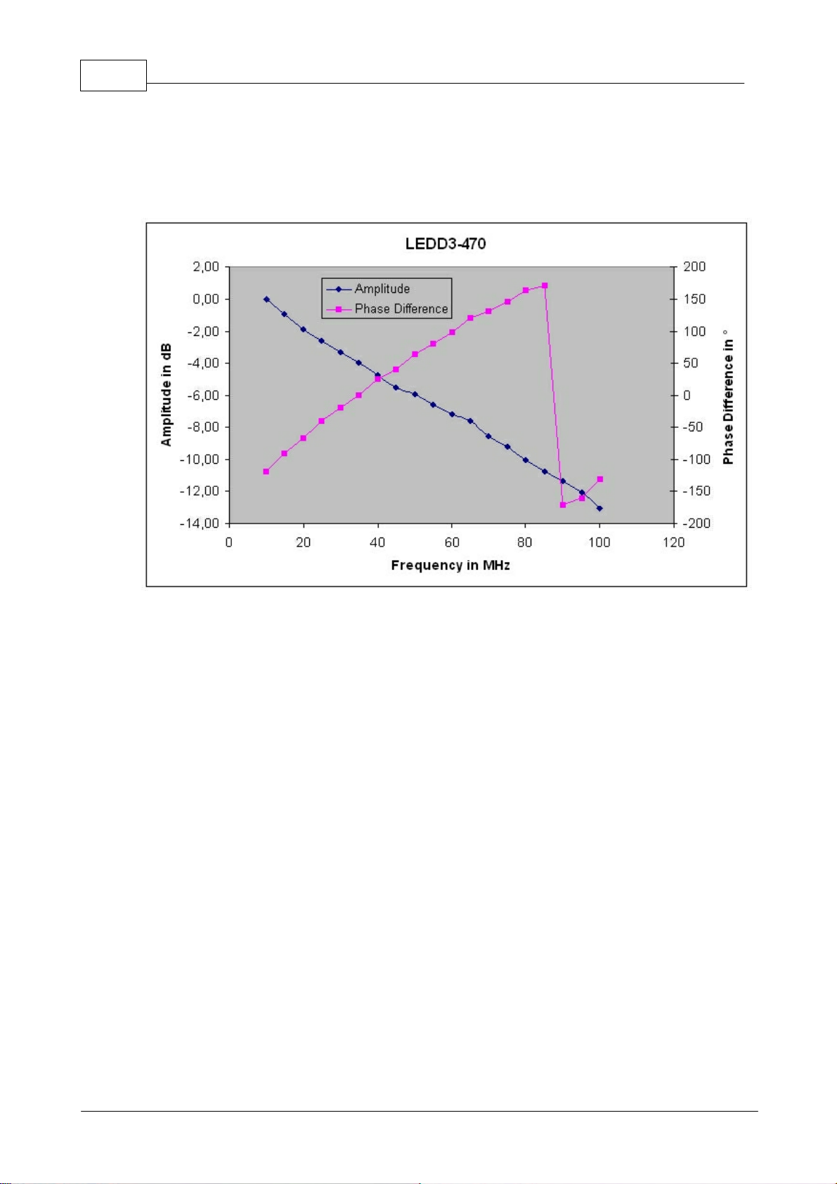
6.3.3.3
LED @ 470nm
The LEDD3-470 contains the blue LED LZ1-00B205 from LedEngin. The LED
emits a wavelength at 470nm and an optical power of up to 60lm.
The 10dB cut-off frequency of the LEDD3-470 is 80MHz. The maximum current is
1000mA.
6.3.3.4
Figure 46 Phase Difference of LEDD3-470
LED @ 630nm
The LEDD3-630 contains the red LED LZ1-00R105 from LedEngin. The LED emits
a wavelength at 630nm and an optical power of up to 100lm.
The 10dB cut-off frequency of the LEDD3-630 is 70MHz. The maximum current is
1000mA.
© 2009 Thorlabs

51Appendix
Figure 47 Phase Difference of LEDD3-630
© 2009 Thorlabs

52 LEDD3 - FLIM LED Driver User Manual
6.4
Thorlabs 'End of Life' Policy (WEEE)
As required by the WEEE (Waste Electrical and Electronic Equipment Directive) of
the European Community and the corresponding national laws, Thorlabs offers all
end users in the EC the possibility to return "end of life" units without incurring
disposal charges.
This offer is valid for Thorlabs electrical and electronic equipment
· sold after August 13
· marked correspondingly with the crossed out 'wheelie bin' logo (see fig. 1)
· sold to a company or institute within the EC
· currently owned by a company or institute within the EC
· still complete, not disassembled and not contaminated
As the WEEE directive applies to self contained operational electrical and electronic
products, this 'end of life' take back service does not refer to other Thorlabs
products, such as
· pure OEM products, that means assemblies to be built into a unit by the user
(e. g. OEM laser driver cards)
· components
· mechanics and optics
· left over parts of units disassembled by the user (PCB's, housings etc.).
th
2005
6.4.1
6.4.2
If you wish to return a Thorlabs unit for waste recovery, please contact Thorlabs or
your nearest dealer for further information.
Waste Treatment on your own Responsibility
If you do not return an 'end of life' unit to Thorlabs, you must hand it to a company
specialized in waste recovery. Do not dispose of the unit in a litter bin or at a public
waste disposal site.
Ecological Background
It is well known that WEEE pollutes the environment by releasing toxic products
during decomposition. The aim of the European RoHS directive is to reduce the
content of toxic substances in electronic products in the future.
The intent of the WEEE directive is to enforce the recycling of WEEE. A controlled
recycling of end of live products will thereby avoid negative impacts on the
environment.
Figure 48 Crossed out "Wheelie Bin" Symbol
© 2009 Thorlabs

Listings
LEDD3 - FLIM LED Driver User
Manual
Part
VII

54 LEDD3 - FLIM LED Driver User Manual
7
7.1
7.2
Listings
List of Acronyms
The following acronyms and abbreviations are used in this manual:
AC Alternating Current
AGND Analog Ground
DC Direct Current
DGND Digital Ground
DLL Dynamic Link Library
FCC Federal Communications Commission
FLIM Fluorescence Lifetime Imaging
GUI Graphical User Interface
IEC International Electrotechnical Commission
LCD Liquid Crystal Display
LED Light Emitting Diode
PC Personal Computer
PCB Printed Circuit Board
USB Universal Serial Bus
List of Figures
Figure 1 Connecting the LED Head
Figure 2 Display and Operating Elements on the Front Panel
Figure 3 Operating Elements on the Rear Panel
Figure 3a Operating Elements on the LED Head
Figure 4 Welcome Screen
Figure 5 Main Menu
Figure 6 Constant Current Mode
Figure 7 Internal Modulation Mode
Figure 6 Internal Modulation - Current Adjustment
Figure 9 Internal Modulation - Frequency Adjustment
Figure 10 Internal Modulation - Modulation Depth Adjustment
Figure 11 Definition of the Parameter Current and Modulation Depth
Figure 12 External Control Mode
Figure 13 Main Menu
Figure 14 LED Current Limit Setting
Figure 15a LED Maximum Current
Figure 15b LED Maximum Frequency
Figure 16 LCD Backlight Brightness Setting
Figure 17 About Panel
Figure 18 Autorun Menu
Figure 19 VISA Installation Start Screen
Figure 20 Selection of the Installation Path
Figure 21 License Agreement
Figure 22 Selection of VISA Features
Figure 23 Finalize Installation
Figure 24 Request for Administrator Privileges
Figure 25 Selecting the Installation Paths
Figure 26 The Device Driver Installer
Figure 27 The Windows Logo Test
© 2009 Thorlabs

Figure 28 Additional Notes
Figure 29 Installation successful
Figure 30 The Found New Hardware Wizard
Figure 31 Choosing the Installation Mode
Figure 32 Finishing the New Found Hardware Wizard
Figure 33 The Start Screen
Figure 34 The Device Selection Dialog
Figure 35 Constant Current Mode
Figure 36 The Internal Modulation Mode
Figure 37 The External Control Mode
Figure 38 User Limit
Figure 39 User Limit Dialog
Figure 40 LED Configuration Menu
Figure 41 LED Maximum Limit
Figure 42 LED Maximum Frequency
Figure 43 No VISA Engine installed
Figure 44 Phase Difference of LEDD3-365
Figure 45 Phase Difference of LEDD3-405
Figure 46 Phase Difference of LEDD3-470
Figure 47 Phase Difference of LEDD3-630
Figure 48 Crossed out "Wheelie Bin" Symbol
55Listings
© 2009 Thorlabs

56 LEDD3 - FLIM LED Driver User Manual
7.3
Addresses
Our Company is represented by several distributors and sales offices throughout the
world.
Europe
Thorlabs GmbH
Hans-Boeckler-Str. 6
D-85221 Dachau / Munich
Germany
Sales and Support
Phone: +49 (0) 81 31 / 5956-0
Fax: +49 (0) 81 31 / 5956-99
Email: europe@thorlabs.com
Web: www.thorlabs.com
USA
Thorlabs, Inc.
435 Route 206 North
Newton, NJ 07860
USA
Sales and Support
Phone: 1-973-579-7227
Fax: 1-973-300-3600
Email: sales@thorlabs.com
Email: techsupport@thorlabs.com
Web: www.thorlabs.com
Japan
Thorlabs, Inc.
1th Floor, Higashi Ikebukuro Q Building
2-32-2, Higashi Ikebukuro, Toshima-ku
Tokyo 170-0013
Japan
Sales and Support
Phone: +81-3-5979-8889
Fax: +81-3-5979-7285
Email: sales@thorlabs.jp
Web: www.thorlabs.jp
Our company is also represented by several distributors and sales offices
throughout the world.
Please call our hotline, send an Email to ask for your nearest distributor or just visit
our homepage http://www.thorlabs.com
© 2009 Thorlabs

Application Note
LEDD3 - FLIM LED Driver User
Manual
Part
VIII

58 LEDD3 - FLIM LED Driver User Manual
8
8.1
8.1.1
Application Note
Fluorescence Lifetime Imaging (FLIM)
FLIM (Fluorescence Lifetime Imaging) is an imaging technology that is primarily
used with confocal microscopy, but the FLIM method has also been applied in other
microscopy methods such as wide field and multiphoton imaging. Especially in the
field of cell and tissue research FLIM is a powerful tool to analyze the distribution of
biological materials.
If a dye molecule is exposed to energy of a specific wavelength, it emits another also
specific wavelength. The color of the emitted light as well as the lifetime of a
fluorescent dye are particular properties of the fluorophore. Due to different
fluorescent dyes the lifetime can vary between a few nanoseconds and several
milliseconds. The lifetime is depended on the ion concentration as well as further
factors like molecular binding, oxygen concentration or hydrophobic properties,
which will provide information about molecules of living cells. The concentration of
the dye, the dimension of the cell or the excitation light intensity will not affect the
lifetime. Therefore, the fluorescence lifetime imaging is a precise measure for ion
concentration.
Time Domain FLIM
The sample will be excited with a light pulse in the ps range. After the pulse the
electrons of the dye will stay in the excited state for a certain time (lifetime). They
return into their ground state and emit a fluorescence photon. The lifetime of the
excited electrons are quite short (ns range). The fluorescence intensity is highest
right after the excitation pulse and decays quickly since there are only a few
electrons with a longer lifetime. The decay can be described with a simple
-t/
exponential function: I(t)=I(t0)*e
Mostly lasers are used to generate pulses with several ps pulse width.
t
.
Figure A1 Time Domain FLIM
© 2009 Thorlabs

59Application Note
8.1.2
Frequency Domain FLIM
The lifetime can also be determined in the frequency domain by using a modulated
light source. The source continuously emits a sine wave signal in the range of 1 to
200MHz and modulates the fluorescence. Due to the lifetime of the electrons in the
excited state there will be a phase shift between the excitation signal and the
fluorescence response. Furthermore, the intensity to the excitation and fluorescence
sine waves will be modulated. The lifetime can be calculated from the modulation
ratio of the intensity. Hence, the FLIM in the frequency domain provides 2 values for
the lifetime.
Figure A2 Frequency Domain FLIM
© 2009 Thorlabs

 Loading...