


LDM56(/M) and LDM90(/M)
Temperature-Controlled Mounts for
Ø5.6 and Ø9 mm Laser Diodes
Operating Manual

Temperature-Controlled Laser Diode Mounts
Table of Contents
Chapter 1 Warning Symbol Definitions ........................................... 1
Chapter 2 Safety ................................................................................. 2
Chapter 3 Description ........................................................................ 3
Chapter 4 Setup .................................................................................. 5
4.1. PackageContents..........................................................5
4.2. LaserInstallation...........................................................5
4.2.1. General Configuration ................................................................. 5
4.2.2. Special Note for G Style Configuration Laser Diodes .................. 7
4.3. LaserDiodeControllerConnection.................................8
4.3.1. Using the Thorlabs LDC/ITC Series Laser Controllers ................ 8
4.3.2. Using a Third-Party Laser Controller ........................................... 8
4.4. TECControllerConnection............................................10
4.4.1. Using the Thorlabs TED Series TEC Controllers ...................... 10
4.4.2. Using a Third-Party TEC controller ............................................ 10
4.5. MountingOtherAccessories........................................11
4.5.1. Mounting Thorlabs Fiber Coupled Pigtailed Lasers ................... 11
4.6. MakingtheSafetyInterlockConnections.....................12
Chapter 5 Operation ......................................................................... 13
5.1. RFModulation.............................................................13
5.2. StatusandInterlocks...................................................14
5.3. TemperatureSensor....................................................15
Chapter 6 Maintenance .................................................................... 16
Chapter 7 Troubleshooting ............................................................. 17
Chapter 8 Specifications ................................................................. 18
Chapter 9 Drawing ........................................................................... 19
Chapter 10 Regulatory ....................................................................... 20
Chapter 11 Thorlabs Worldwide Contacts....................................... 21

Temperature-Controlled Laser Diode Mounts Chapter 1: Warning Symbol Definitions
Chapter 1 Warning Symbol Definitions
Below is a list of warning symbols you may encounter in this manual or on your
device.
Symbol Description
Direct Current
Alternating Current
Both Direct and Alternating Current
Earth Ground Terminal
Protective Conductor Terminal
Frame or Chassis Terminal
Equipotentiality
Rev C, February 20, 2018 Page 1
On (Supply)
Off (Supply)
In Position of a Bi-Stable Push Control
Out Position of a Bi-Stable Push Control
Caution: Risk of Electric Shock
Caution: Hot Surface
Caution: Risk of Danger
Warning: Laser Radiation
Caution: Spinning Blades May Cause Harm

Temperature-Controlled Laser Diode Mounts Chapter 2: Safety
Chapter 2 Safety
!
This unit must not be operated in explosive environments
Avoid exposure – laser radiation emitted from apertures.
WARNING
WARNING
!
Page 2 TTN121126-D02

Temperature-Controlled Laser Diode Mounts Chapter 3: Description
Chapter 3 Description
Features
Supports Ø5.6 mm or Ø9 mm Pinout Spacing TO-Can Lasers
Integrated TEC Lockout Circuit to Protect Laser Diode (Can Be
Disabled)
Integrated Bias-T Adapter Allows for RF Modulation of LD Current up to
600 MHz
= T
8 W Heat Dissipation @ T
ambient
TEC Element Prolongs LD Life, Stabilizes Output Power, and Stabilizes
Wavelength
The LDM56(/M) and LDM90(/M) mounts by Thorlabs are ideal for temperaturecontrolled operation of most 3 and 4-pin laser diodes in Ø5.6 mm (TO-56) and
Ø9 mm (TO-9) packages, respectively. The mount can control the laser diode
and monitor photodiode independently making it compatible with a wide variety of
laser diodes including all three-pin style A, B, and C configuration laser diodes,
two-pin style E, G, and H configurations, and all four-pin style D laser diodes.
The LDM56(/M) and LDM90(/M) are also compatible with style G laser diodes by
setting an internal jumper as discussed in section 4.2.2. Please note that style F
laser diodes are incompatible with the LDM56(/M) and LDM90(/M) mounts.
Laser diodes can be quickly and easily changed in the mount. It is as simple as
inserting the laser diode into the socket according to the imprinted pin
assignment and fastening the mounting flange with two screws. The diode socket
is located very close to the front of the cold plate making the connection of short
lead devices easier.
The LDM56(/M) and LDM90(/M) can be easily integrated into any existing optical
setup. The mounting options include multiple 1/4"-20 (M6) mounting holes, and
its front plate is equipped with tapped holes to mount our 30 mm Cage System
and SM1 threading for use with our Lens Tube Assemblies.
The LDM56(/M) and LDM90(/M) includes a Bias-T for RF modulation of the laser
current up to 600 MHz. The mount can be adapted to the polarity of the laser
diode and monitor diode by miniature switches located at the top of the mount.
User protection features include an LED indicating an enabled laser located
along the top of the mount and a remote interlock connector located on the side.
Laser protection features include optional grounding configurations and the TEC
lockout circuit (only useable with our controllers) that prevents enabling the laser
unless the TEC controller is active. The built-in TE cooler enables temperaturecontrolled operation of the laser diode. The mounting flange protects the laser
diode against air drafts, thus temperature stabilities of about 10 mK can be
achieved.
= 25 °C
laser
Rev C, February 20, 2018 Page 3

Temperature-Controlled Laser Diode Mounts Chapter 3: Description
r
LD Switch
Laser On
Indicator
PD Switch
DIP Switches
Pin Code
Select Jumpe
LD Driver
Connector
RF Input
(SMA))
TEC Driver
Connector
Remote
Interlock
Figure 1 Location of Features
Page 4 TTN121126-D02

Temperature-Controlled Laser Diode Mounts Chapter 4: Setup
Chapter 4 Setup
4.1. Package Contents
LDM56(/M) or LDM90(/M) Mount
Diode Retainer(s):
o LDM56(/M): 5.6 mm TO-Can Laser Diode Mounting Flange
o LDM90(/M): 9.0 mm Standard and 9.0 mm High Heat Load
Laser Diode Mounting Flanges
2-56 x 1/8" Screws for Mounting Flange
2-56 x 1/4" Screws for Pigtails Laser Diodes
Hex Key
Operating Manual
4.2. Laser Installation
4.2.1. General Configuration
! !
Make sure the laser diode is installed correctly and the polarity switches on the
driver side are set as per the laser diode pin configuration provided by the
manufacturer. Connecting the LD driver to mount with incorrect installation will
Use of thermal grease is not recommended for use with the TO-can laser diode
mount. Thermal grease will creep and eventually contaminate the laser facet.
To install the laser diode, complete the following steps:
1. Unpack the laser mount. Removing the cover is optional when installing
an A, B, C, D, E, or H pin style laser. If a laser diode with a G style pin
code is being used, follow the steps in section 4.2.2.
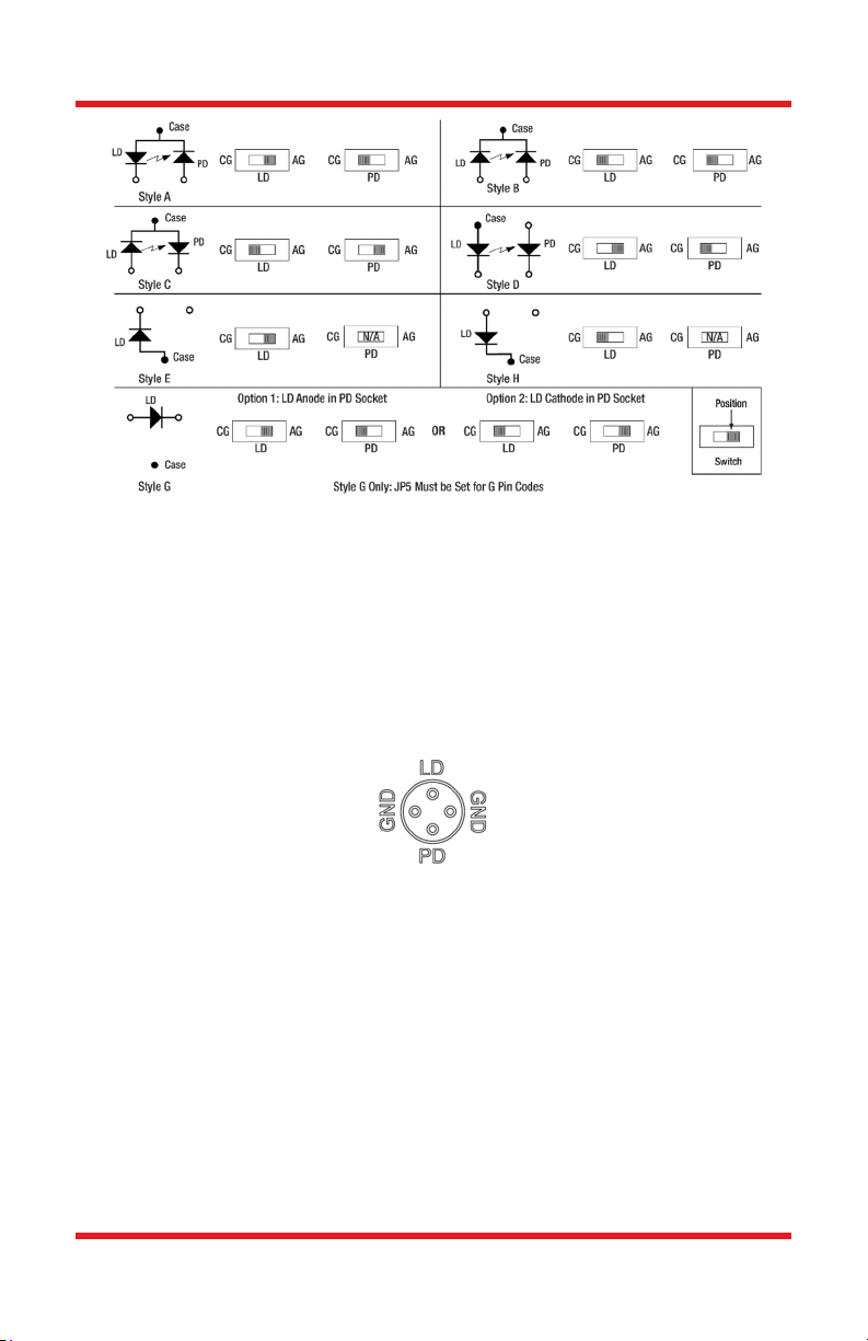
2. Determine the laser pin configuration from the laser diode
manufacturer’s data sheets and set the LD (Laser Diode) and PD
(Photodiode) switches located on the top of the unit according to Figure
2.
WARNING
damage the laser diode.
WARNING
Rev C, February 20, 2018 Page 5
Temperature-Controlled Laser Diode Mounts Chapter 4: Setup
Figure 2 Polarity Switch Settings
3. Most laser diodes are three pins with the case tied to one of the laser
pins and also to one of the photodiode pins. The other laser and
photodiode pin will be isolated from the case. The LDM56(/M) and
LDM90(/M) mounts were designed to operate the laser case at ground
potential, therefore this common pin will be inserted into either the 3
o’clock or the 9 o’clock position of the laser connector. Locate the
isolated laser pin and insert it in the 12 o’clock position. The isolated
photodiode should now be in the 6 o’clock position. Refer to the figure
below.
Figure 3 LD and PD Orientation
4. Install the laser mounting flange and the cover. Install both screws
through the mounting flange and loosely into the cold plate, then
carefully tighten each screw a little bit at a time until the flange is just
snug. Do not over tighten either screw – the flange will sit slightly above
the cold plate. If removed during installation reinstall the cover using the
four 2-56 cap head screws provided.
Note: The four sockets comprising the laser diode connector are 0.6" deep, laser
diode leads do not need to be cut unless they are longer than 0.6".
Note: The laser connector is located close enough to the front face of the copper
cold plate to allow easy installation of short leaded lasers. The clearance area
around the LD and PD sockets is sufficient to prevent the pins from contacting
the cold plate.
Page 6 TTN121126-D02

Temperature-Controlled Laser Diode Mounts Chapter 4: Setup
4.2.2. Special Note for G Style Configuration Laser Diodes
Figure 4 LDM56(/M) and LDM90(/M) Internal Circuitry Showing Jumper JP5
In order to drive a style G laser diode, the PD pin in the mount must be
grounded. The red jumper is set across the bottom and left pin for operation with
A, B, C, D, E, and H pin code laser diodes (Figure 5). The jumper is set across
the center and right pin for operation with G pin code laser diodes (Figure 6). The
G pin code setting grounds the photodiode pin which allows the mount to drive a
laser diode only (no photodiode) configuration with the LD pin at the 12 o'clock
position.
5. If the mount will be used with a G style laser diode, unscrew the four
captive 4-40 socket head screws from the front cover using a 5/64" hex
driver.
6. Locate JP5 header and move the red jumper as shown below or in the
note beside the header.
Figure 5 JP5 Position for A, B, C, D, E, & H Pin Code TO-Can Lasers
Figure 6 JP5 Position for G Pin Code TO-Can Lasers
Rev C, February 20, 2018 Page 7
Temperature-Controlled Laser Diode Mounts Chapter 4: Setup
Note: Once the jumper is set for operation of the mount with G style laser diodes
it must be set back to the A, B, C, D, E, and H pin code position for operation
with those diodes.
4.3. Laser Diode Controller Connection
4.3.1. Using the Thorlabs LDC/ITC Series Laser Controllers
The LDM56(/M) and LDM90(/M) is compatible with all Thorlabs LDC LD
controllers and ITC series combination controllers (LD and TEC).
Appropriate cables with DB9 connectors are included with Thorlabs
controllers and ensure that the controllers cannot be connected
incorrectly. Additionally, these controllers have built-in protection
circuitry that protects the laser when not in use.
The nomenclature for the laser diode polarity switch on the LDC/ITC
driver and the LDM56(/M) and LDM90(/M) are consistent with each
other. For example, if the laser polarity on the driver is set to AG (anode
grounded), then the LD polarity switch on the LDM56(/M) and
LDM90(/M) should also be set to AG, and so forth.
The nomenclature for the photodiode polarity switch on the
LDC40xx/80xx and ITC series drivers and the LDM56(/M) and
LDM90(/M) is as follows: The photodiode polarity switch on the
LDM56(/M) and LDM90(/M) must always be set to “CG.” The
photodiode polarity should be set with the internal laser controller switch
only. For more information on how to set polarity settings on the laser
controller, please refer to the appropriate laser controller manual.
4.3.2. Using a Third-Party Laser Controller
When using a third-party controller, a custom cable will have to be made to
properly interface to the laser mount. Please refer to the table on page 9 for laser
connections.
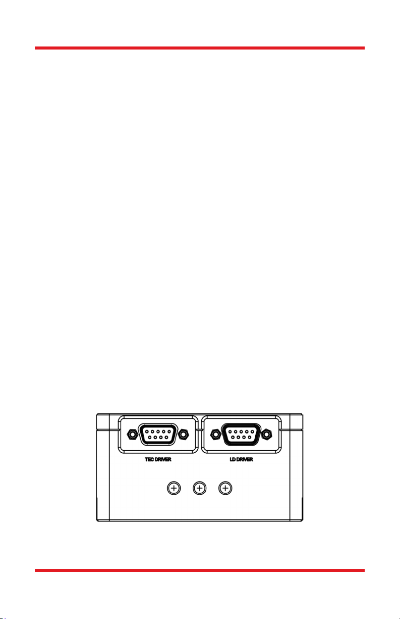
1 5
6 9
Figure 7 Pin Out for LD Driver and TEC Driver Connectors
Page 8 TTN121126-D02
5 1
9 6

Temperature-Controlled Laser Diode Mounts Chapter 4: Setup
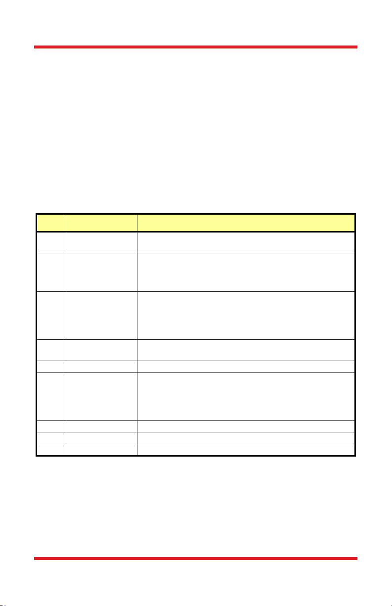
Pin Signal Description
Interlock and
1
(LDC Specific)
Interlock and
5
Status Return
7
8
Laser Ground
3
2
4
Status Pin
Laser Diode
Cathode
Laser Diode
Anode
(Case)
Photodiode
Cathode
Photodiode
Anode
This pin is the input to the LD Status Indicator and Interlock
Circuits. When using Thorlabs LDCs no external circuitry is
required. To use these features with third-party controllers
please refer to the Status and Interlock section of this manual.
This pin is the return side of the Status and Interlock circuitry.
This pin is connected to the 12 o’clock pin on the laser socket
when the LD Polarity Switch is set to AG
1
. Otherwise it is
floating.
This pin is connected to the 12 o’clock pin on the laser socket
when the LD Polarity Switch is set to CG
2
. Otherwise it is
floating.
This pin is connected to the 3 o’clock and 9 o’clock pins on
the laser socket and corresponds to the settings of the LD and
PD polarity switches. i.e. If the LD and PD switches are set to
AG then this pin grounds the Anodes of the laser and photo
diodes.
This pin is connected to the 6 o’clock pin on the laser socket
when the PD Polarity Switch is set to AG. It is attached to
ground and the 3 o’clock and 9 o’clock pins on the laser
socket when the PD Polarity Switch is set to CG.
This pin is connected to the 6 o’clock pin on the laser socket
when the PD Polarity Switch is set to CG. It is attached to
ground and the 3 o’clock and 9 o’clock pins on the laser
socket when the PD Polarity Switch is set to AG.
This pin is connected to LD Interface Pin 7, thru a 499 Ω
resistor, when the LD Polarity Switch is set to AG. It is
attached directly to LD Interface Pin 3 when the LD Polarity
Switch is set to CG.
This pin is connected to LD Interface Pin 8, thru a 499 Ω
resistor, when the LD Polarity Switch is set to CG. It is
attached directly to LD Interface Pin 3 when the LD Polarity
Switch is set to AG.
6
9
Laser Diode
Voltage
(Cathode)
Laser Diode
Voltage
(Anode)
1
AG stands for Anode Ground.
2
CG stands for Cathode Ground.
Rev C, February 20, 2018 Page 9
Temperature-Controlled Laser Diode Mounts Chapter 4: Setup
4.4. TEC Controller Connection
4.4.1. Using the Thorlabs TED Series TEC Controllers
The LDM56(/M) and LDM90(/M) is best used with Thorlabs TED200 or related
TEC controllers. The TED series are shipped with a mating DB9 cable that plugs
directly into the controller and laser mount. Using the cable supplied with the
TED, the controller cannot be connected incorrectly. Simply connect the cable
included with the TED to the Laser Mount and to the controller.
4.4.2. Using a Third-Party TEC controller
When using a third-party controller, a custom cable will have to be made to
properly interface to the laser mount. Please refer to the table below for laser
connections:
Pin Signal Description
4 +TEC
-TEC and TEC
5
1 TEC Lockout (+)
2 +Thermistor
3 -Thermistor The thermistor return pin.
7 AD592 (-)
9 AD592 (+) The positive terminal of the AD592.
6 N.C. Not Used
8 N.C. Not Used
Lockout (-)
This pin is connected to the positive terminal of the TEC
element.
This pin is connected to the negative terminal of the TEC
element, and also is common to the cathode of the photorelay of the TEC Lockout circuit – refer to the Status and
Interlock section of this manual.
This pin is connected to the anode of the photo-relay side
of the TEC Lockout circuit. When using Thorlabs TEDs no
external circuitry is required. To use these features with
third-party controllers please refer to the Status and
Interlock section of this manual.
The 10 k at 25 C NTC thermistor (provided for
temperature feedback).
The negative terminal of the AD592 temperature
transducer. When using Thorlabs TEDs no external
circuitry is required. To use this device with third party
controllers it must be properly biased. Refer to Analog
Devices AD592 Data for application information.
Page 10 TTN121126-D02
Temperature-Controlled Laser Diode Mounts Chapter 4: Setup
4.5. Mounting Other Accessories
The LDM56(/M) and LDM90(/M) includes an SM1 (1.035"-40) threaded hole
centered on the laser for mounting our SM1 series of optics mounts. This is most
often used for mounting aspheric collimating optics.
Each mount also has four 4-40 tapped holes at the corners of the mount for
compatibility with the LDMXY Flexure Adapter, which provides ±1.0 mm of XY
translation for collimation optics.
Also included are eight 4-40 tapped holes for attaching Thorlabs 30 mm or
60 mm cage assembly products. Using the combination of the SM1 threaded
mount and cage assembly products, a wide variety of optical systems can be
easily assembled form off-the-shelf products.
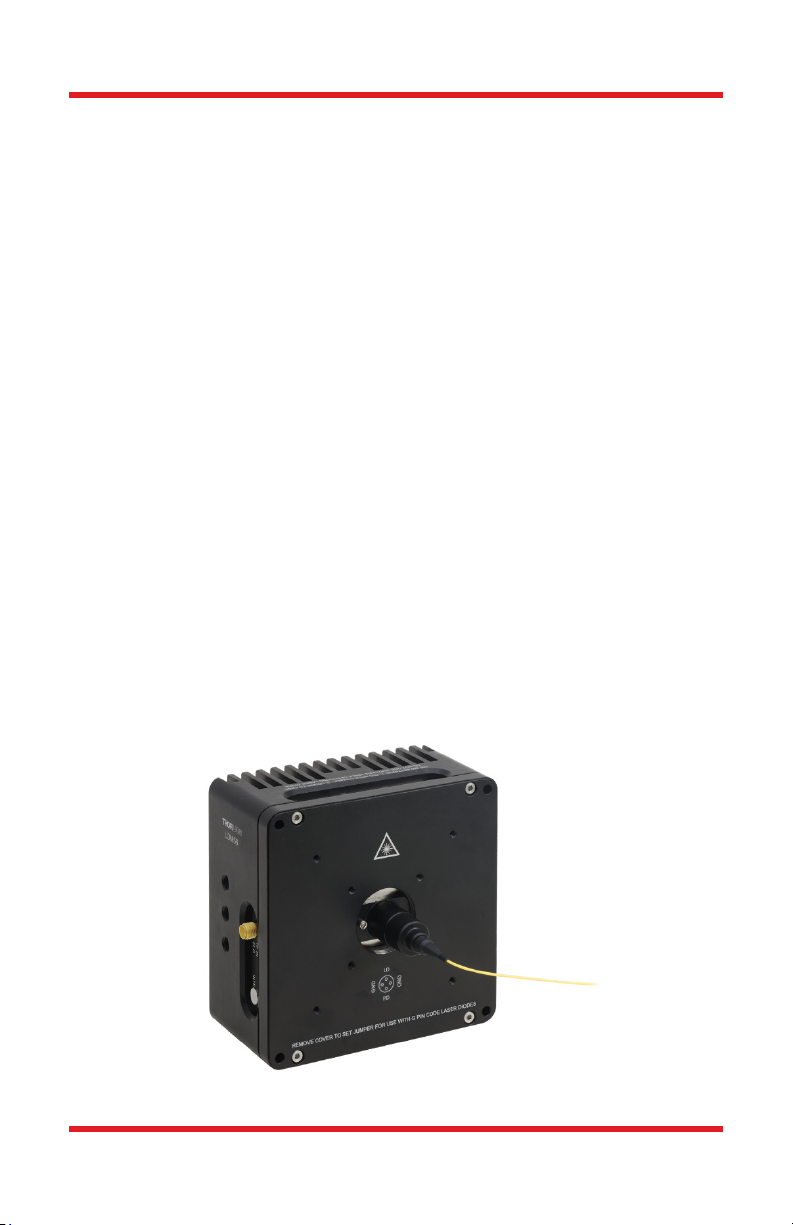
4.5.1. Mounting Thorlabs Fiber Coupled Pigtailed Lasers
Ensuring that the pins are correctly aligned, mount the pigtail housing directly
onto the cold-plate, as shown in Figure 8 below. Note that these mounts are not
optimized for use with pigtailed lasers so TEC performance and compatibility are
not guaranteed. If primarily using pigtailed lasers, we suggest using the LDM9LP
or CLD1011LP.
1. Install the pigtailed laser into the mount's socket, observing the proper
polarity of the laser to the socket (the pigtail’s pin-outs are provided with
the pigtail data sheet).
2. Make sure the pigtail’s laser diode leads are fully inserted into the
socket. The mounting holes on the laser housing should be lined up with
the threaded holes on the cold-plate as shown in the photo below.
3. Secure the housing to the cold-plate using two (2) 2-56 x 1/4" cap head
screws (included).
Figure 8 Installing Fiber Pigtailed Laser
Rev C, February 20, 2018 Page 11

Temperature-Controlled Laser Diode Mounts Chapter 4: Setup
4.6. Making the Safety Interlock Connections
The LDM56(/M) and LDM90(/M) is equipped with a Remote Interlock connector
located on the side panel. In order to enable the laser source, a short circuit must
be applied across the terminals of the remote interlock connector. In practice this
connection is made available to allow the user to connect a remote actuated
switch to the connector (i.e. an open door indicator). The switch (which must be
normally open) has to be closed in order for the unit to be enabled. Once the
switch is in an open state the laser diode must automatically shut down.
All units are shipped configured with a shorting device installed in the interlock
connector. If you are not going to use this feature then you can leave the shorting
device installed and the unit will operate normally as described in the procedures
in this manual. If you wish to make use of the interlock feature you will need to
acquire the appropriate connector mate and wire it your remote interlock switch.
Next, remove the shorting device by pulling it from the input and install the
connector into the interlock input.
The interlock input only accepts a 2.5 mm mono phono jack. This connector is
readily available at most electronics suppliers.
The electrical specifications for the interlock input are as follows:
Specification Value
Type of Mating Connector 2.5 mm Mono Phono Jack
Open Circuit Voltage
Short Circuit Current 10 mA DC Typical
Connector Polarity Tip is positive, barrel is ground.
Interlock Switch Requirements
+5 VDC with Respect to System Ground
(When used in conjunction with Thorlabs
drivers.)
Must be N.O. Dry Contacts (Under no
circumstances should any external
voltages be applied to the Interlock input.)
Figure 9 Remote Interlock Connector
Page 12 TTN121126-D02

Temperature-Controlled Laser Diode Mounts Chapter 5: Operation
Chapter 5 Operation
With the laser mounted and the laser controller and temperature controller
connected, the LDM56(/M) and LDM90(/M) is ready to operate. Please refer to
the operating instructions for the laser and temperature controller for specific
operating instructions.
When operating at low temperatures in high humidity climates the laser mount
may develop internal condensation. If this occurs, turn the laser off, open the
case and allow the mount to dry off completely before re-using.
5.1. RF Modulation
The LDM56(/M) and LDM90(/M) has an RF input for modulating the laser with an
external RF source up to 600 MHz. This is a 50 Ω input that is AC-coupled
directly to the laser through a Bias-Tee network. To calculate the desired RF
power to modulate the laser determine the amount of modulating current needed
from the laser manufacturer’s data sheets and use the following calculations:
50ΩLDModulatingCurrent
It is strongly recommended that you start off conservatively by a factor of 10
below the calculated modulating voltage and slowly bring the RF power up until
the desired depth of modulation is reached. Use the laser controller to establish
the DC operating point of the laser.
!
The RF input is directly coupled to the laser. Any excessive transients or noise
will be coupled into the laser and may cause the laser to be overdriven. In
addition, the laser can be easily overdriven if excessive RF power is applied to
this input. Use the RF modulation input with care to avoid damaging your laser.
Rev C, February 20, 2018 Page 13
WARNING
Max RF Power 200 mW
!

Temperature-Controlled Laser Diode Mounts Chapter 5: Operation
5.2. Status and Interlocks
This unit is equipped with two interlock circuits and an LED that indicates if the
laser diode is enabled. All three circuits are designed to interface with our laser
and TEC controllers with no external circuitry.
The first interlock circuit is controlled by the Interlock connector outlined in
section 4.6. The second interlock is the TEC Interlock DIP SW 1. When the dip
switch is in the down position shown the TEC interlock circuit is closed, enabling
operation.
Figure 10 Switches on Top of LDM56(/M) and LDM90(/M) Mounts
DIP Switch 2 allows the user to internally tie the LD ground to earth ground when
in the down position as shown above. Care should be taken when setting the
LDGND switch. It should be noted this is commonly left open and is only needed
if using a controller that is floating, has no path to earth ground.
If third party controllers are used to drive the laser diode or TEC elements then
only the LD ON indicator can be used. To prevent damage to the Status and
Interlock circuits the following external connections should be followed:
1. Install the shorting device into the INTERLOCK connector that was
shipped with the LDM56(/M) and LDM90(/M).
2. Connect a resistor to LD Interface DB9 Pin 1 appropriately sized to limit
the current into Pin 1 to between 5 – 10 mA.
3. The “driver” side of this resistor should be connected to a DC signal
that, when high, indicates that the laser diode is being driven.
4. If you have any questions regarding these connections please feel free
to contact an engineer at Thorlabs for clarification.
If you wish to make full use all of the status and interlock features with your third
party drivers, please contact your local Tech Support office. An engineer will help
you determine if this is possible and how to implement these features.
Page 14 TTN121126-D02

Temperature-Controlled Laser Diode Mounts Chapter 5: Operation
5.3. Temperature Sensor
The LDM56(/M) and LDM90(/M) includes a 10 kΩ thermistor for temperature
feedback. We recommend setting the sensor type to Thermistor (low) when
operating with a Thorlabs ITC or TED4xxx series controller. The graph below
shows the typical thermistor resistance versus temperature. Full thermistor
specifications can be found in Chapter 8.
Figure 11 Thermistor Resistance vs. Temperature
Rev C, February 20, 2018 Page 15

Temperature-Controlled Laser Diode Mounts Chapter 6: Maintenance
Chapter 6 Maintenance
There are no serviceable parts in the LDM56(/M) and LDM90(/M). The housing
may be cleaned by wiping with a soft damp cloth. If you suspect a problem with
your LDM56(/M) and LDM90(/M), please call Thorlabs and an engineer will be
happy to assist you.
Page 16 TTN121126-D02

Temperature-Controlled Laser Diode Mounts Chapter 7: Troubleshooting
Chapter 7 Troubleshooting
Problem Solution
Remote Interlock is open.
Make sure that either the “shorting device” is installed in
the INTERLOCK connector on the side of the LDM56(/M)
Laser Driver will not
enable.
(If you are using
Thorlabs Laser and TEC
controllers with your
LDM56(/M) and
LDM90(/M) mount.)
Laser wavelength or
power is unstable even
though the TEC
controller shows a stable
temperature.
The LDC series laser
driver indicates an “Open
Circuit” alarm when the
laser is enabled.
The LD does not have an
integrated photodiode,
how does it get installed
and how do the polarity
switches get set?
and LDM90(/M). If you have a remote interlock switch
connected to this INTERLOCK connector it must be in a
closed position.
TEC LOCKOUT circuit is active and the TED series TEC
controller is not enabled.
To determine if you have selected the TEC LOCKOUT
circuit to be active refer to section 5.2. If it is selected
then the TED series TEC controller must be enabled first
before the LDC series laser controller can be enabled.
Make sure your laser diode is fully inserted into the
LDM56(/M) and LDM90(/M) laser socket and its body is
in full contact with the nickel plated cold plate.
Make sure the appropriate mounting flange is installed
over your laser. There are two different flanges; one
specifically for 5.6 mm diodes, one for 9 mm diodes, one
for high heat 9 mm diodes, and a DPSS flange that is
sold separately (LDM56DJ).
The LD and PD polarity switch settings are incorrect.
Refer to Figure 2 and the data sheet for your specific
laser diode to ensure the proper settings. The LD polarity
switch setting on your LDM56(/M) and LDM90(/M) must
also match the LD polarity switch setting on the rear
panel of your LDC series laser diode controller.
The laser diode is installed into the wrong pins on the
laser diode socket. Refer to Figure 3 for the correct
orientation of the laser diode pins and compare this to
the data sheet for your laser diode.
If your laser diode has one of its two active leads
common to the case of the laser, that lead must be
connected to one of the “GND” sockets on the laser
diode connector (refer to Figure 3) while the other pin is
connected to the “LD” socket in the 12 o’clock position.
Depending on the pin orientation of your laser you might
be using either the “GND” socket at 3 o’clock or the
“GND” socket at 9 o’clock. Refer to your laser diode data
for pin orientation. If your Cathode pin is common to the
body of your laser diode, set the LD polarity switch to
“CG”. If your Anode pin is common to the body of your
laser diode, set the LD polarity switch to “AG”. The
setting for the PD polarity switch is irrelevant.
Rev C, February 20, 2018 Page 17

Temperature-Controlled Laser Diode Mounts Chapter 8: Specifications
Chapter 8 Specifications
Specification Value
Laser Specs
Laser Diodes Supported
Max Laser Current 2 A (T
Laser Pin Configurations3
Pin Lead Diameter 0.015" – 0.020" (0.38 – 0.51 mm)
Pin Lead Length, Max 0.6" (15.24 mm)
RF Modulation Frequency 100 kHz to 600 MHz
RF Input Impedance
Max RF Power 200 mW
RF Input Connector SMA
Interlock Connector 2.5 mm Phono Jack
Laser Interface DB9 Female
TEC Specs
Max TEC Current 5 A
Max TEC Voltage 4 V
TEC Heating / Cooling Capacity 8 W (T
Typical Temperature Range
(LD Dependent)
Temperature Sensor
Thermistor
TEC Interface DB9 Male
General
Size
Weight 1.9 lbs (0.87 kg)
Operating Temperature 10 to 40 °C
Storage Temperature 10 to 80 °C
Accessory Mounting SM1 (1.035"-40) Series Internal Thread
Cage Compatibility
Mounting Holes
LDM56(/M): Ø5.6 mm TO Can
LDM90(/M): Ø9 mm TO Can
= 25 °C)
ambient
A, B, C, D, E, G, and H LD Packages,
Switch Selectable
50
= 25 °C)
ambient
0 to 70 C
AD592AN (1 A/K)
10 k ± 3% at 25 C, NTC
Beta = 3977 K ± 0.75%
4.00" x 4.00" x 2.07"
(101.6 mm × 101.6 mm × 52.6 mm)
4-40 Taps (8 Places) for
30 mm and 60 mm Cage Systems
LDM56, LDM90: 1/4"-20 (9 Places)
LDM56/M, LDM90/M: M6x1.0 (9 Places)
3
Note that G style LD configuration requires setting an internal jumper of the LDM56(/M)
and LDM90(/M) mount. Refer to section 4.2.2.
Page 18 TTN121126-D02

Temperature-Controlled Laser Diode Mounts Chapter 9: Drawing
Chapter 9 Drawing
Figure 12 Mechanical Diagram of LDM56(/M) and LDM90(/M) Mounts
(Imperial Mounting Holes: 1/4"-20, Metric Mounting Holes: M6)
Rev C, February 20, 2018 Page 19

Temperature-Controlled Laser Diode Mounts Chapter 10: Regulatory
Chapter 10 Regulatory
As required by the WEEE (Waste Electrical and Electronic Equipment Directive)
of the European Community and the corresponding national laws, Thorlabs offers
all end users in the EC the possibility to return “end of life” units without incurring
disposal charges.
This offer is valid for Thorlabs electrical and electronic equipment:
Sold after August 13, 2005
Marked correspondingly with the crossed out
“wheelie bin” logo (see right)
Sold to a company or institute within the EC
Currently owned by a company or institute
within the EC
Still complete, not disassembled and not
contaminated
As the WEEE directive applies to self-contained
operational electrical and electronic products, this end of
life take back service does not refer to other Thorlabs products, such as:
Pure OEM products, that means assemblies to be built into a unit by the
user (e.g. OEM laser driver cards)
Components
Mechanics and optics
Left over parts of units disassembled by the user (PCB’s, housings etc.).
If you wish to return a Thorlabs unit for waste recovery, please contact Thorlabs
or your nearest dealer for further information.
Waste Treatment is Your Own Responsibility
Wheelie Bin Logo
If you do not return an “end of life” unit to Thorlabs, you must hand it to a
company specialized in waste recovery. Do not dispose of the unit in a litter bin
or at a public waste disposal site.
Ecological Background
It is well known that WEEE pollutes the environment by releasing toxic products
during decomposition. The aim of the European RoHS directive is to reduce the
content of toxic substances in electronic products in the future.
The intent of the WEEE directive is to enforce the recycling of WEEE. A
controlled recycling of end of life products will thereby avoid negative impacts on
the environment.
Page 20 TTN121126-D02

7HPSHUDWXUH&RQWUROOHG/DVHU'LRGH0RXQWV&KDSWHU7KRUODEV:RUOGZLGH&RQWDFWV
Chapter Thorlabs Worldwide Contacts
USA, Canada, and South America
Thorlabs, Inc.
56 Sparta Avenue
Newton, NJ 07860
USA
Tel: 973-300-3000
Fax: 973-300-3600
www.thorlabs.com
www.thorlabs.us (West Coast)
Email: sales@thorlabs.com
Support: techsupport@thorlabs.com
Europe
Thorlabs GmbH
Hans-Böckler-Str. 6
85221 Dachau / Munich
Germany
Tel: +49-(0) 8131-5956-0
Fax: +49-(0) 8131-5956-99
www.thorlabs.de
Email: europe@thorlabs.com
France
Thorlabs SAS
109, rue des Côtes
78600 Maisons-Laffitte
France
Tel: +33 (0) 970 444 844
Fax: +33 (0) 825 744 800
www.thorlabs.com
Email: sales.fr@thorlabs.com
Japan
Thorlabs Japan, Inc.
3-6-3, Kitamachi,
Nerima-ku, Tokyo 179-0081
Japan
Tel: +81-3-6915-7701
Fax: +81-3-6915-7716
www.thorlabs.co.jp
Email: sales@thorlabs.jp
UK and Ireland
Thorlabs Ltd.
1 Saint Thomas Place
Ely CB7 4EX
Great Britain
Tel: +44 (0) 1353-654440
Fax: +44 (0) 1353-654444
www.thorlabs.com
Email: sales.uk@thorlabs.com
Support: techsupport.uk@thorlabs.com
Scandinavia
Thorlabs Sweden AB
Bergfotsgatan 7
431 35 Mölndal
Sweden
Tel: +46-31-733-30-00
Fax: +46-31-703-40-45
www.thorlabs.com
Email: scandinavia@thorlabs.com
Brazil
Thorlabs Vendas de Fotônicos Ltda.
Rua Riachuelo, 171
São Carlos, SP 13560-110
Brazil
Tel: +55-16-3413 7062
Fax: +55-16-3413 7064
www.thorlabs.com
Email: brasil@thorlabs.com
China
Thorlabs China
Room A101, No. 100, Lane 2891,
South Qilianshan Road
Putuo District
Shanghai 200331
China
Tel: +86 (0) 21-60561122
Fax: +86 (0) 21-32513480
www.thorlabschina.cn
Email: chinasales@thorlabs.com
Rev &, )HEUXDU\, 2018 Page

www.thorlabs.com
 Loading...