

LCC25
Liquid Crystal Controller
Operating Manual

Liquid Crystal Controller
Table of Contents
Part 1. Important Safety Notice .................................................................. 4
Part 2. Product Overview ............................................................................ 5
Part 3. Setup and Operation ........................................................................ 7
AC Line Voltage .............................................................................................................. 7
Powering ON the LCC25 ................................................................................................ 7
Setting the Voltage and Modulation Frequency .............................................................. 7
Setting the Output ............................................................................................................ 8
Internal Modulation Frequency ....................................................................................... 8
External Modulation Frequency ...................................................................................... 8
Computer Controlled Operation ...................................................................................... 9
3.1. LCC25 Controls and Features .............................................................. 11
Part 4. LCC25 Specifications ..................................................................... 12
4.1. Mechanical Drawing .............................................................................. 13
Part 5. Maintenance ................................................................................... 14
5.1. Fuse Replacement .................................................................................. 14
5.2. Ventilation .............................................................................................. 14
5.3. Troubleshooting ..................................................................................... 15
Part 6. Warranty Information ................................................................... 16
Part 7. Declaration of Conformity ............................................................ 17
Part 8. Regulatory ...................................................................................... 18
Part 9. Thorlabs Worldwide Contacts ...................................................... 19
18828-D02 Rev F, Sept 23, 2011 Page 2 www.thorlabs.com

Liquid Crystal Controller
Table of Figures
Figure 1: A 2 kHz Square Wave Output with no Additional Modulation ..................... 5
Figure 2: A 2 kHz Square Wave Output with 150 Hz Modulation ................................ 6
Figure 3: Front Display ................................................................................................. 6
Figure 4: LCC25 Front Panel ...................................................................................... 11
Figure 5: LCC25 Rear Panel Features ......................................................................... 11
Figure 6: LCC25 Mechanical Drawing ....................................................................... 13
18828-D02 Rev F, Sept 23, 2011 Page 3 www.thorlabs.com
Liquid Crystal Controller
Part 1. Important Safety Notice
Do Not Open Housing!
The LCC25 has no user-serviceable parts. Service should only be
performed by trained service personnel.
All statements regarding safety of operation and technical data in this instruction manual
will only apply when the unit is operated correctly.
SHOCK WARNING
High voltage inside. To avoid electrical shock, before powering
unit, make sure that the protective conductor of the 3-conductor
power cord is correctly connected to the protective earth contact of
the socket outlet. Improper grounding can cause electric shock
resulting in severe injury or even death. Do not operate without
cover installed.
WARNING
This unit must not be operated in explosive environments
Unit is supplied with a 115 V parallel blade line cord for North American use only. For
all other applications use an IEC 320 compatible line cord fitted with a plug appropriate
for your particular AC wall socket.
Make sure that the line voltage rating marked on the rear panel agrees with your local
supply and that the appropriate fuses are installed. Changing of the mains fuse can be
done by the user (see Setting the AC Line Voltage and Installing Fuses). With the
exception of the mains fuses, there are no user serviceable parts in this product.
WARNING
Do Not Operate in Wet/Damp conditions. Do not obstruct the air-
ventilation slots in the housing!
Mobile telephones, cellular phones or other radio transmitters should not to be used
within the range of three meters of this unit since the electromagnetic field intensity may
exceed the maximum allowed disturbance values according to EN50082-1.
18828-D02 Rev F, Sept 23, 2011 Page 4 www.thorlabs.com
Liquid Crystal Controller
Part 2. Product Overview
The LCC25 is a liquid crystal controller compatible with all Thorlabs LC Variable
Retarders. The LCC25 will drive most nematic liquid crystal devices. The liquid crystal
device is connected to the BNC voltage output port. The amplitude of the output voltage,
adjusted by the front panel knob, and external signal, and a computer via a USB interface,
controls the retardance of the LC device.
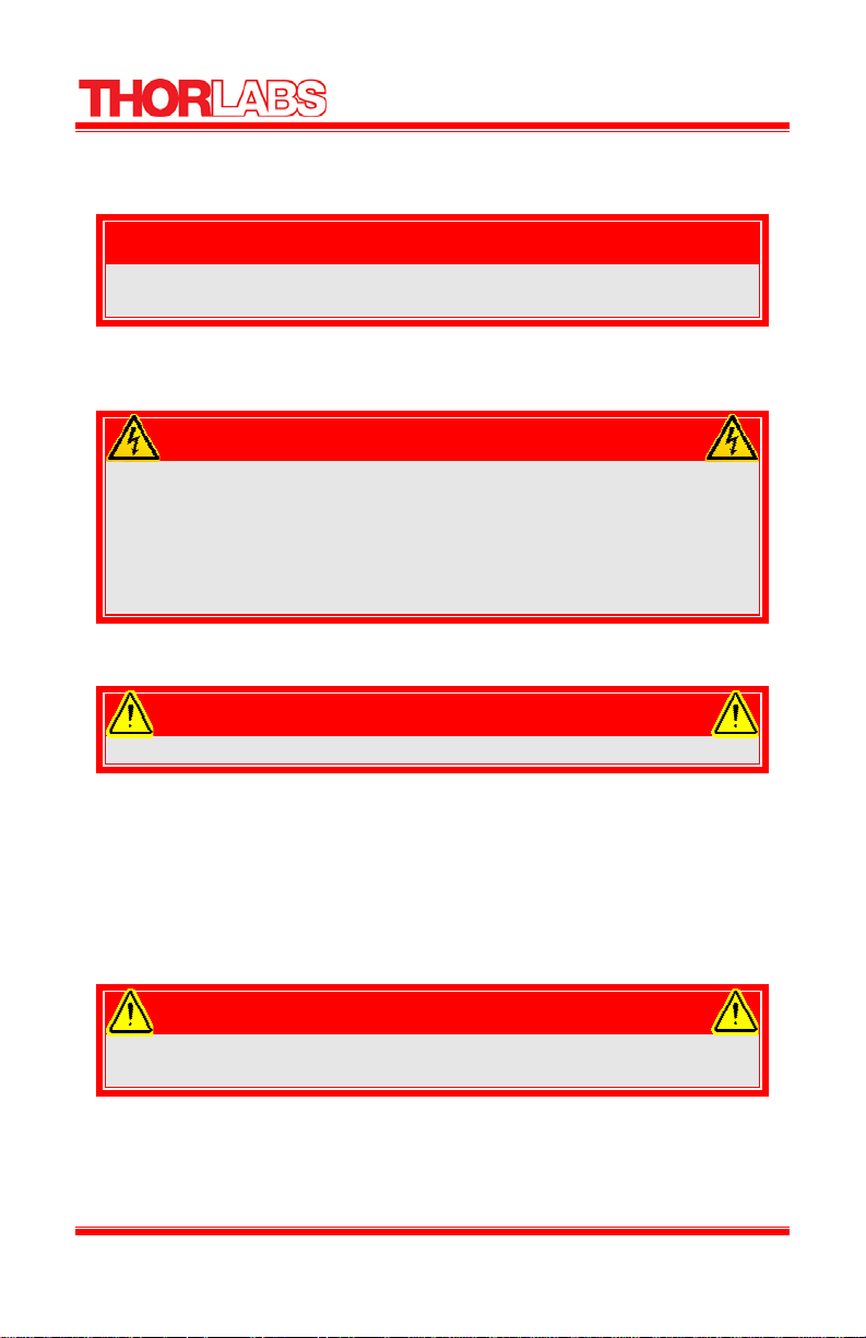
The LCC25 produces a 2 kHz AC square wave with an amplitude that is adjustable from
0 to 25 V
The unit features two selectable set points, Voltage 1 and Voltage 2. Both set points are
controlled by the user, and they produce a square wave that is plus/minus the set point.
For example, if the user sets Voltage 1 to 15.000, the output would be a ±15.000V, 2 kHz
square wave (see figure 1).
RMS
.
Figure 1: A 2 kHz Square Wave Output with no Additional Modulation
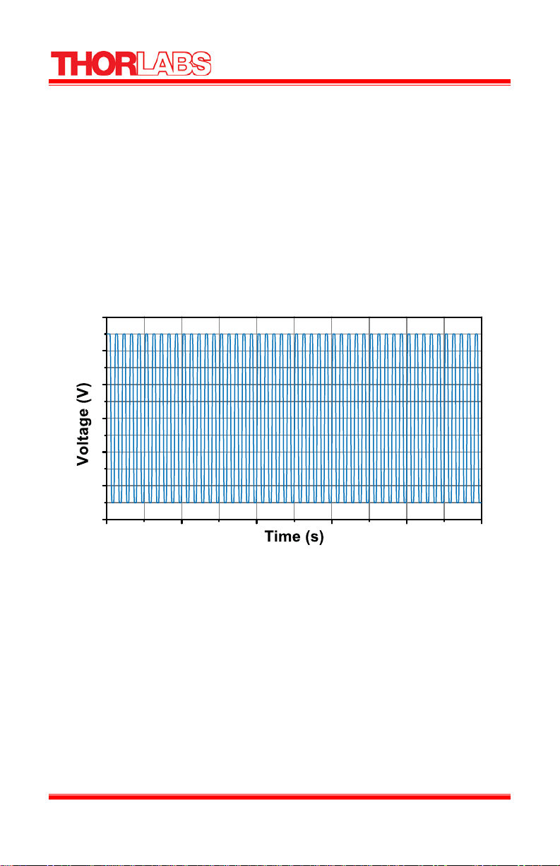
The user can also select a modulated output with a frequency range of 0.5 to 150 Hz. The
First cycle will be equal to Voltage 1 and the second cycle will be equal to Voltage 2 (see
figure 2)
18828-D02 Rev F, Sept 23, 2011 Page 5 www.thorlabs.com
Liquid Crystal Controller
Figure 2: A 2 kHz Square Wave Output with 150 Hz Modulation
The LCC25 will automatically detect and correct any DC offset in real time to within ±10
mV. This feature increases the life of the liquid crystal device.
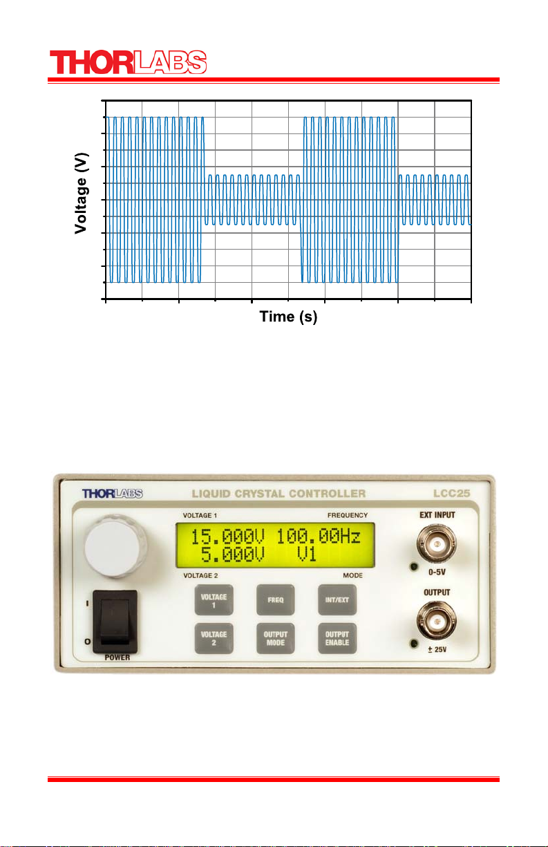
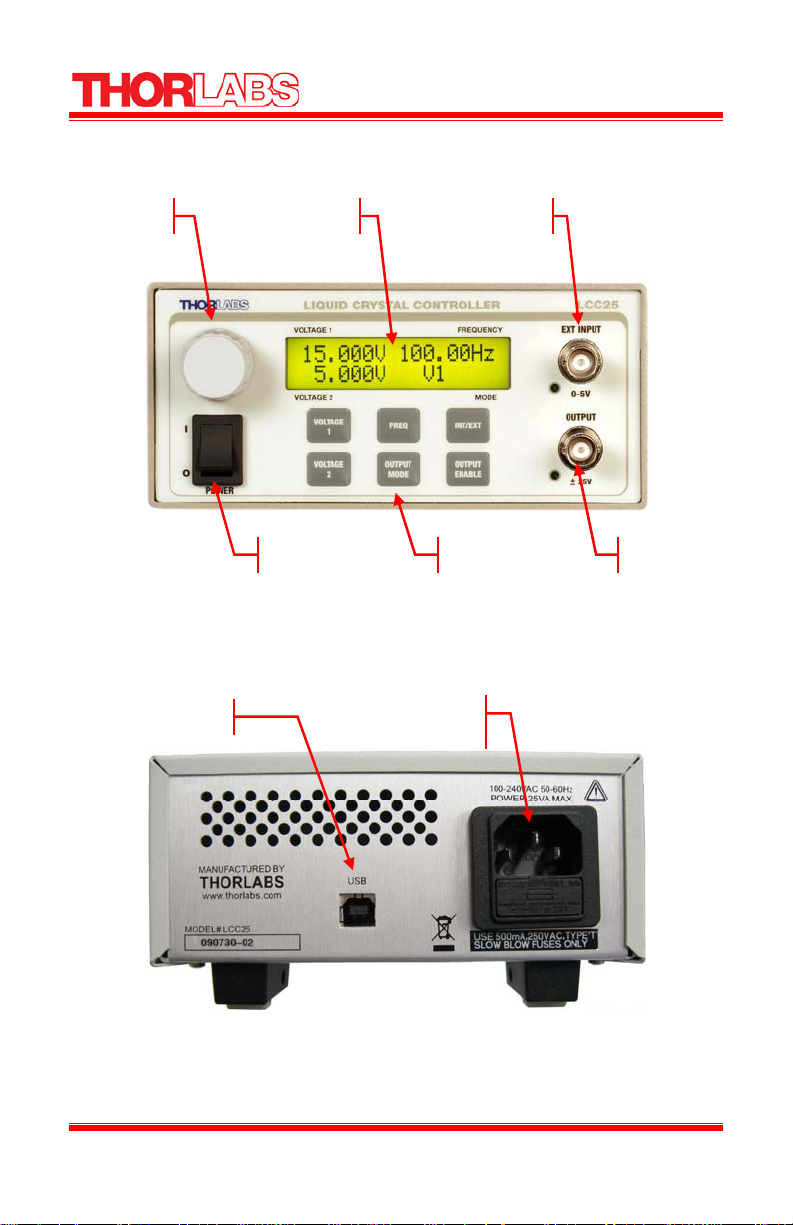
The device can be controlled using tactile buttons on the front panel to select the voltage
and frequency and then using the knob to adjust the levels. The system’s display is a
16 x 2 LCD which displays the voltages and frequency (see figure 3). There are two BNC
connectors. The top BNC is the external input and allows the user to input an external
modulation frequency square wave up to 5 volts. The bottom BNC is the system output.
Figure 3: Front Display
The LCC25 may also be controlled by a command line language through the USB port.
This is offered to enable operation through a terminal interface or for those who may
want to write their own program to control the unit.
18828-D02 Rev F, Sept 23, 2011 Page 6 www.thorlabs.com

Liquid Crystal Controller
Part 3. Setup and Operation
To setup the unit, refer to Figures 4 and 5, and the legend table on the preceding page and
perform the following steps:
NOTE: For optimal performance a warm up time of at least 30 minutes is
recommended.
AC Line Voltage
The LCC25 is designed to operate at 100 to 240 VAC operation. There is no line switch
adjustment to be made. However it may be necessary to replace an open fuse. To do this
you must perform the following procedure on page 14, Fuse Replacement.
Powering ON the LCC25
• Connect the appropriate power cord into the AC receptacle and plug the unit in.
• Set power switch to the ON position. Thorlabs will scroll across the display.
Voltage 1, Voltage 2, and the Frequency then will be displayed.
• BNC Output and External input LED indicators will be OFF. This is the default
state when the unit is power on.
Setting the Voltage and Modulation Frequency
There is a set of 6 buttons beneath the LCD display and a knob for adjustment to the left
of the display.
• To change Voltage 1 press the VOLTAGE 1 key, the LCD top left will flash.
Adjust the knob to the desired Voltage.
• To change Voltage 2 press the VOLTAGE 2 key, the LCD bottom left will
flash. Adjust the knob to the desired Voltage.
• To change Frequency Modulation, press the FREQ key, the LCD top right will
flash. Adjust the knob to the desired Frequency.
After pressing the key, the selected voltage or frequency can be saved by pressing the key
while the cursor is flashing or by letting the cursor time out in about 5 seconds. These
settings will be saved during power down and retrieved on power up.
18828-D02 Rev F, Sept 23, 2011 Page 7 www.thorlabs.com

Liquid Crystal Controller
Setting the Output
Output Mode has three selections. Pressing the OUTPUT MODE key will toggle through
each mode. The selected mode will be indicated in the bottom right of the LCD display.
The sequence is as follows: Voltage 1, Voltage 2, and Modulation. To activate the output,
press the OUTPUT ENABLE button. When active, the LED indicator next to the
OUTPUT BNC connector will be lit.
The supported modes are:
• Voltage 1: The output signal will be a 2 kHz
square wave with an RMS voltage level equal
to the value set by Voltage 1
• Voltage 2: The output signal will be a 2 kHz
square wave with an RMS voltage level equal
to the value set by Voltage 2.
• Modulation: The output signal will be a 2 kHz
square wave at an RMS voltage level
switching between the value currently set for
Voltage 1 and the value set for Voltage 2 at the
currently selected frequency.
Internal Modulation Frequency
The LCC25 has internal modulation frequency adjustable from 0.5 to 150 Hz. To use the
internal modulation, the LED next to the EXT INPUT BNC connect should be off. If it is
lit, press the INT/EXT key disabling the LED indicator. To adjust the modulation
frequency, push the FREQ key and adjust the knob to the desired output.
External Modulation Frequency
The LCC25 can be modulated by an external input. The modulation frequency device is
connected to the EXT INPUT BNC. The input signal can be any waveform with a
frequency from 0.5 to 500 Hz, and any duty cycle, but must be 0 and 5 Volts to trigger
the flip. The output from the LCC25 will be modulated based on the input frequency with
Voltage 1 being the high and Voltage 2 being the low.
To select the external modulation, the LED next to the EXT INPUT BNC connector
should be on. If it is not lit, press the INT/EXT key enabling the LED indicator. When the
external input is enabled, the top right of LCD will display EXT and bottom right will
switch to the modulation square -wave symbol (same as modulation is shown above.
18828-D02 Rev F, Sept 23, 2011 Page 8 www.thorlabs.com

Liquid Crystal Controller
Computer Controlled Operation
The LCC25 may also be controlled by a command line language through the USB port.
This is offered to enable operation through a terminal interface or for those who may
want to write their own program to control the unit. The command language is described
below. Prior to running the command line interface, the included drivers should be
installed, the unit should be powered, and a USB cable should be connected between the
LCC25 and the host.
The terminal emulator should be set as follows:
• Baud Rate: 115.2k b/s (bits per second)
• Data Bits: 8
• Parity: None
• Stop Bits: 1
• Flow Control: None
If the connection is correct and after pressing the Enter key, you will see the following:
Command error CMD_NOT_DEFINED followed by the command prompt, “>”
The basic structure of the interface is a keyword followed by either an equals sign (=) or
a question mark (?). The (=) or (?) will determine if the string is a command or a query.
All strings, commands and queries, must be terminated by a carriage return (CR) or
pressing the ENTER key on the computer.
The command structure is as follows:
Keyword = argument (CR)
Where “keyword” defines the function and “argument” is a numerical value followed by
a carriage return (CR).
The query structure is a follows:
Keyword? (CR)
The “keyword” defines the function and the question mark (?) indicates a query. The
string is terminated with a carriage return (CR).
There are a few exceptions to this which are noted below, also noted are unique shortcut
keys. The following table lists the commands and queries available with this device. The
prompt symbol (>) will appear on power up and after a command is accepted by the
LCC25 indicating it is ready to receive another command line.
If the keyword, format, or argument are incorrect or out of range the unit will return an
error string.
18828-D02 Rev F, Sept 23, 2011 Page 9 www.thorlabs.com

Liquid Crystal Controller
Command Syntax* Description
Get ID *idn? Returns the model number and firmware version
Set Voltage 1 volt1=(n) Where (n) equals a voltage between 0 and 25V
Get Voltage 1 volt1? Returns the current voltage set for Voltage 1
Set Voltage 2 volt2=(n) Where (n) equals a voltage between 0 and 25V
Get Voltage 2 volt2? Returns the current voltage set for Voltage 2
Set Modulation Frequency freq=(n) Where (n) equals a frequency between 5 and 150 Hz
Get Modulation Frequency freq? Returns the current modulation frequency
mode=0 Sets output mode to Modulation
Set Output Mode
Get Output Mode mode? Returns the current output mode
Set Output Enable
Get Output Enable enable? Returns current output enable state
Set External Modulation extern=(n) Where (n) is 0 for internal modulation and 1 for
Get External Modulation extern? Returns current modulation mode – internal or
Set Preset set=(n) Stores the current settings in the preset (n)
Get Preset get=(n) Restores the settings saved in the preset (n)
Save Parameters save Stores parameters in static memory
Restore Default Parameters default Restores the initial factory settings
Set Test Mode Dwell Time (mS) dwell=(n) Sets the dwell time for LC Test Mode
Get Test Mode Dwell Time (mS) dwell? Returns the current dwell time for LC Test Mode
Set Test Mode Increment (V) increment=(n) Sets the voltage step increment for LC Test Mode
Get Test Mode Increment (V) increment? Returns the current voltage step increment for LC
Set Test Min Voltage (V) min=(n) Sets the starting voltage level for LC Test Mode
Get Test Min Voltage (V) min? Returns the current starting voltage level for LC Test
Set Test Max Voltage (V) max=(n) Sets the ending voltage level for LC Test Mode
Get Test Max Voltage (V) max? Returns the current ending voltage level for LC Test
Run Test Mode test Starts the LC Test Mode that will step the output
Remote not shown on Display
Normal use of button on display
Remote shown on Display and
current Set voltage
Locks out use of buttons
Command Query ? Returns a list of these commands
mode=1 Sets output mode to Voltage 1
mode=2 Sets output mode to Voltage 2
enable=0 Output is disabled
enable=1 Output is enabled
external
external
Test Mode
Mode
Mode
voltage from the min voltage to the max voltage by
steps equal to increment. At each voltage level it will
delay for the time specified by dwell.
remote=0 Disables remote from being shown on display.
remote=1 Enables remote shown on display and displays
Normal operation
current Set voltage.
Locks out buttons on from panel.
*) All commands and queries are in lower case letters.
18828-D02 Rev F, Sept 23, 2011 Page 10 www.thorlabs.com
Liquid Crystal Controller
r
3.1. LCC25 Controls and Features
Rotary Knob LCD Display External Input BNC
USB
Main Power Switch Function Keys Output BNC
Figure 4: LCC25 Front Panel
AC Input Connector-IEC
and Fuse Drawe
Figure 5: LCC25 Rear Panel Features
18828-D02 Rev F, Sept 23, 2011 Page 11 www.thorlabs.com
Liquid Crystal Controller
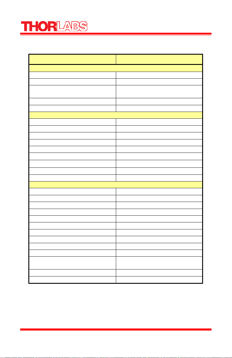
Part 4. LCC25 Specifications
Specification Description
Max Ratings
Max Output Current 15 mA
Max External Input Voltage 5 VDC
Fuse Rating
*See replacement spec. page 14
Operating Temperature Range 10 to 40 °C
Maximum Relative Humidity 85%
Electrical Characteristics
External Input Voltage 0 to 5 VDC Square Wave
Adjustable Output Voltage ± 25 V
Voltage resolution 1.0 mV
Adjustable Internal Modulation Frequency 0.5 to 150 Hz @ 50% Duty Cycle
Switching Frequency 2,000 ± 5 Hz, 50% Duty Cycle
Slew Rate
DC offset ±10 mV
AC Power 85 – 264 VAC, 47 – 63 Hz, 25 VA
Warm Up Time 30 Minutes
Physical Features
External Input Connector BNC
External Input Enable Front Panel: INT/EXT enable Key
External Input Indicator Green LED
Output Connector BNC
Output Enable Front Panel: OUTPUT ENABLE Key
Output Indicator Green LED
Rotary Knob Digital Encoder
Display LCD 16 x 2
Power Switch Rocker Switch
USB interface USB Standard B Plug
Dimensions 5.75” x 3″ x 12.2″
146 mm x 78 mm x 309 mm
Weight 3.6 lbs
Other Tilting Rubber-Padded Feet
500 mA,
5 x 20 mm SLO-BLO
10 V/μs
18828-D02 Rev F, Sept 23, 2011 Page 12 www.thorlabs.com

Liquid Crystal Controller
4.1. Mechanical Drawing
12.160"
(308.88mm)
11.425"
(290.2mm)
5.758"
(146.26mm)
2.586"
(65.69mm)
3.066"
(77.88mm)
Figure 6: LCC25 Mechanical Drawing
18828-D02 Rev F, Sept 23, 2011 Page 13 www.thorlabs.com

Liquid Crystal Controller
Part 5. Maintenance
The LCC25 amplifier needs very little maintenance under normal operating conditions.
The enclosure may be cleaned by wiping with a soft damp cloth.
There are no serviceable parts in the LCC25 and no reason to open the unit. If you
suspect a problem with your LCC25 please call Thorlabs and technical support will be
happy to assist you.
5.1. Fuse Replacement
The AC input is protected by a fuse located in a pull out compartment drawer on the rear
panel AC connector. If replacement is required:
• Remove the AC power cord if it is connected to the unit.
• Locate the Fuse tray directly below the AC power cord connection on the
rear panel of the unit.
• Carefully use a flat blade screwdriver to open the fuse tray.
• Remove the existing fuse and install the appropriate 500mA fuse. The
replacement fuse must be a 5 mm x 20 mm 250 VAC Type T Fuses (IEC
60127-2/III, low breaking capacity, slow blow), see fuse specification
below.
• Push the fuse tray back into place making sure that it snaps and seats
correctly.
• Connect the appropriate power cord into the AC receptacle and plug the
unit in.
* Replace the fuse with the correct rating and type. It is not recommended to use a fuse
other than what is specified. Do not use a fuse with a current rating higher than the unit
is rated for.
Fuse specification:
• Manufacturer: Littlefuse
• Manufacturer part#: 0218.500HXP
• Description: Fuse, 0.500A 250V IEC SLO 5x20mm 218 series
• Thorlabs part#: 4300-GMC-250-500MA
5.2. Ventilation
For proper operation and protection, it is important that the ventilation passages located
on the sides and rear of the unit not be obstructed from free airflow.
18828-D02 Rev F, Sept 23, 2011 Page 14 www.thorlabs.com

Liquid Crystal Controller
5.3. Troubleshooting
Problem Solutions
Unit will not power up. LCD display not
illuminating, unit is not functioning
DC Offset Error
Note: The LCC25 circuitry has been designed to monitor and correct the DC offset in real
time. This will increase the life of the Liquid Crystals. For any unforeseen reason DC
offset is detected above the ±10 mV limit enabling the DC OFFSET ERROR to appear.
To eliminate damage to the LC device disconnect from LCC25 output BNC.
Check the power switch is in the ON position,
the mains connection is correct, and the fuse
has not been damaged.
If Error appears on LCD. Disconnect LC
device from the output of the LCC25. Cycle
power switch to reset parameters. If ERROR
reappears, please contact Thorlabs technical
support for assistance.
18828-D02 Rev F, Sept 23, 2011 Page 15 www.thorlabs.com

Liquid Crystal Controller
Part 6. Warranty Information
General Product Warranty
Thorlabs warrants that all products sold will be free from defects in material and
workmanship, and will conform to the published specifications under normal use and
service when correctly installed and maintained.
Opto-Mechanics
Lifetime Warranty: Thorlabs offers a lifetime warranty on all opto-mechanical components.
Thorlabs will repair or replace any opto-mechanical product which after evaluation has
failed to perform in the above conditions.
Optical Tables and Breadboards
Lifetime Warranty: We provide a lifetime guarantee that all of our passively damped optical
tables and breadboards will meet all originally stated performance specifications under
normal use and proper handling. We additionally guarantee that all our table tops and
breadboards, both active and passive, will be free from defects in workmanship, including
de-lamination of the skins under normal use and handling.
Lasers and Imaging Systems
Thorlabs offers a one year warranty on all lasers and imaging systems, with the exceptions
of laser diodes. Some products are warranted for the number of hours specified in the
operating manual of each laser.
Opto-Electronics, Control Electronics, Optics, and Nano-Positioning Product Lines
Thorlabs offers a two year warranty on the above mentioned product lines, provided normal
use and maintenance of the products and when properly handled and correctly installed.
Thorlabs shall repair or replace any defective or nonconforming product as detailed above.
We ask that buyer contact Thorlabs for a Return Material Authorization number (RMA #)
from our Customer Service/Returns department in order to most efficiently process the
return and/or repair.
Products returned for repair that are not covered under warranty, a Thorlabs standard repair
charge shall be applicable in addition to all shipping expenses. This repair charge will be
quoted to the customer before the work is performed.
Warranty Exclusions
The stated warranty does not apply to Products which are (a) specials, modifications, or
customized items (including custom patch cables) meeting the specifications you provide;
(b) ESD sensitive items whose static protection packaging has been opened; (c) items
repaired, modified or altered by any party other than Thorlabs; (d) items used in conjunction
with equipment not provided by, or acknowledged as compatible by, Thorlabs; (e) subjected
to unusual physical, thermal, or electrical stress; (f) damaged due to improper installation,
misuse, abuse, or storage; (g) damaged due to accident or negligence in use, storage,
transportation or handling.
18828-D02 Rev F, Sept 23, 2011 Page 16 www.thorlabs.com
Liquid Crystal Controller
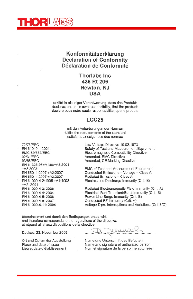
Part 7. Declaration of Conformity
18828-D02 Rev F, Sept 23, 2011 Page 17 www.thorlabs.com

Liquid Crystal Controller
Part 8. Regulatory
As required by the WEEE (Waste Electrical and Electronic Equipment Directive) of the
European Community and the corresponding national laws, Thorlabs offers all end users
in the EC the possibility to return “end of life” units without incurring disposal charges.
• This offer is valid for Thorlabs electrical and
electronic equipment:
• Sold after August 13, 2005
• Marked correspondingly with the crossed out
“wheelie bin” logo (see right)
• Sold to a company or institute within the EC
• Currently owned by a company or institute within
the EC
• Still complete, not disassembled and not
contaminated
As the WEEE directive applies to self contained operational
electrical and electronic products, this end of life take back service does not refer to other
Thorlabs products, such as:
• Pure OEM products, that means assemblies to be built into a unit by the user
(e.g. OEM laser driver cards)
• Components
• Mechanics and optics
• Left over parts of units disassembled by the user (PCB’s, housings etc.).
If you wish to return a Thorlabs unit for waste recovery, please contact Thorlabs or your
nearest dealer for further information.
Wheelie Bin Logo
8.1. Waste Treatment is Your Own Responsibility
If you do not return an “end of life” unit to Thorlabs, you must hand it to a company
specialized in waste recovery. Do not dispose of the unit in a litter bin or at a public
waste disposal site.
8.2. Ecological Background
It is well known that WEEE pollutes the environment by releasing toxic products during
decomposition. The aim of the European RoHS directive is to reduce the content of toxic
substances in electronic products in the future.
The intent of the WEEE directive is to enforce the recycling of WEEE. A controlled
recycling of end of live products will thereby avoid negative impacts on the environment.
18828-D02 Rev F, Sept 23, 2011 Page 18 www.thorlabs.com

Liquid Crystal Controller
Part 9. Thorlabs Worldwide Contacts
USA, Canada, and South America
Thorlabs, Inc.
56 Sparta Avenue
Newton, NJ 07860
USA
Tel: 973-579-7227
Fax: 973-300-3600
www.thorlabs.com
www.thorlabs.us (West Coast)
Email: sales@thorlabs.com
Support: techsupport@thorlabs.com
Europe
Thorlabs GmbH
Hans-Böckler-Str. 6
85221 Dachau
Germany
Tel: +49-(0)8131-5956-0
Fax: +49-(0)8131-5956-99
www.thorlabs.de
Email: europe@thorlabs.com
France
Thorlabs SAS
109, rue des Côtes
78600 Maisons-Laffitte
France
Tel: +33 (0) 970 444 844
Fax: +33 (0) 825 744 800
www.thorlabs.com
Email: sales.fr@thorlabs.com
Japan
Thorlabs Japan, Inc.
--, .LWDPDFKL,
1HULPD-ku, Tokyo 17-00
Japan
Tel: +81-3--
Fax: +81-3--
www.thorlabs.FRjp
Email: sales@thorlabs.jp
UK and Ireland
Thorlabs Ltd.
1 Saint Thomas Place, Ely
Cambridgeshire CB7 4EX
Great Britain
Tel: +44 (0)1353-654440
Fax: +44 (0)1353-654444
www.thorlabs.com
Email: sales.uk@thorlabs.com
Support: techsupport.uk@thorlabs.com
Scandinavia
Thorlabs Sweden AB
Mölndalsvägen 3
412 63 Göteborg
Sweden
Tel: +46-31-733-30-00
Fax: +46-31-703-40-45
www.thorlabs.com
Email: scandinavia@thorlabs.com
China
Thorlabs China
Room A101, No. 100
Lane 2891, South Qilianshan Road
Putuo District
Shanghai
China
Tel: +86 (0)21-32513486
Fax: +86 (0)21-32513480
www.thorlabs.hk
Email: chinasales@thorlabs.com
18828-D02 Rev F, Sept 23, 2011 Page 19 www.thorlabs.com

www.thorlabs.com
 Loading...