


KST101
K-Cube Stepper Motor Controller
APT User Guide
Original Instructions

Contents
Chapter 1 Safety .............................................................................................4
1.1 Safety Information .................................................................................. 4
1.2 General Warnings .................................................................................. 4
Chapter 2 Overview and Setup ..................................................................... 5
2.1 Introduction ............................................................................................. 5
2.2 K-Cube Controller Hub ........................................................................... 6
2.3 APT PC Software Overview ...................................................................7
2.3.1 Intro duction ..................................................................................................... ....7
2.3.2 APTUser Utility ................................................................................................... 8
2.3.3 APT Config Utility ...............................................................................................9
2.3.4 APT Server (ActiveX Controls) .........................................................................10
2.3.5 Software Upgrades ...........................................................................................11
Chapter 3 Getting Started ............................................................................ 12
3.1 Install The Software .................................................................... .......... 12
3.2 Mechanical Installation .........................................................................13
3.3 Electrical Installation ............................................................................. 14
3.4 Connect The Hardware ........................................................................ 16
3.5 Use with Legacy Actuators and Stages ...................................... ... .. ..... 17
3.6 Verifying Software Operation ...............................................................18
Chapter 4 Standalone Operation ................................................................ 20
4.1 Introduction ........................................................................................... 20
4.2 Control Panel ....................................................................................... 21
4.2.1 Digital Display - Operating Mode ......................................................................21
4.3 Velocity Wheel Operation ............................... ... .. ............................... ..22
4.3.1 Homing ............................................................................................................. 22
4.3.2 Go to Position ................................................................................................... 22
4.3.3 Jogging .............................................................................................................22
4.3.4 Velocity Moves .................................................................................................23
4.4 Settings Menu ............................ ... ............................ ... ........................23
4.4.1 Overview ..........................................................................................................23
4.4.2 Menu Option - Go to position ...........................................................................24
4.4.3 Menu Option - Start homing .............................................................................25
4.4.4 Menu Option - Velocity .....................................................................................25
4.4.5 Menu Option - Joystick Mode ........................................................................... 26
4.4.6 Menu Option - Jog Step Size ...........................................................................27
4.4.7 Menu Option - Teach Position .......................................................................... 28
4.4.8 Menu Option - Brightness .................................................................................29
4.4.9 menu Option - Disp.Level.................................................................................. 29
4.4.10 Menu Option - Disable ......................................................................................30
4.4.11 Menu Option - Select stage .............................................................................. 31
Continued...
2 HA0362T Rev C Jan 2017

K-Cube Stepper Motor Controller
Chapter 5 PC Operation - Tutorial ............................................................. 32
5.1 Introduction ........................................................................................... 32
5.2 Using the APT User Utility ....................................................................32
5.3 Homing Motors ........................... ... ............................ .. .........................34
5.4 Moving to an Absolute Position ............................................................35
5.5 Changing Motor Parameters ................................................................36
5.6 Jogging .................................................................................................37
5.7 Stopping the Stage ...................................... .........................................38
5.8 Graphical Control Of Motor Positions (Point and Move) .......................39
5.9 Setting Move Sequences ......................................................................41
5.10 Creating a Simulated Configuration Using APT Config ........................44
5.11 Stage/Axis Tab ..................................................................... ................47
Chapter 6 Software Reference .................................................................... 48
6.1 Introduction ........................................................................................... 48
6.2 GUI Panel .............................................................................................48
6.3 Settings Panel .................................................. ... .................................50
6.3.1 Moves/Jogs Tab ............................................................................................... 50
6.3.2 Stage/Axis Tab ................................................................................................. 55
6.3.3 Panel/Triggering Tab ....................................................................................... 58
6.3.4 Rotation StagesTab ......................................................................................... 63
Appendices
Appendix A Rear Panel Connector Pinout Details .................................... 64
Appendix B Preventive Maintenance ......................................................... 65
Appendix C Specifications ..... ................................. ... ... ... .... ... ... ... .... ... ... ... . 66
Appendix D Motor Control Method Summary ........................................... 68
Appendix E Stepper Motor Operation - Background .. ... .... ... ... ... .... ...... ... . 72
Appendix F Regulatory ........ ... .... ... ... ... .... ... ................................ ... .... ... ... ... . 78
Appendix G Thorlabs Worldwide Contacts ............................................... 81
3

Chapter 1 Safety
1.1 Safety Information
For the continuing safety of the operators of this equipment, and the protection of the
equipment itself, the operator should take note of the Warnings, Cautions and Notes
throughout this handbook and, where visible, on the product itself.
The following safety symbols may be used throughout the handbook and on the
equipment itself.
Shock Warning
Given when there is a risk of injury from electrical shock.
Warning
Given when there is a risk of injury to users.
Caution
Given when there is a risk of damage to the product.
Note
Clarification of an instruction or additional information.
1.2 General Warnings
Warnings
If this equipment is used in a manner not specified by the manufactu rer, the
protection provided by the equipment may be impaired. In particular,
excessive moisture may impair operation.
Spillage of fluid, such as sample solutions, should be avoided. If spillage does
occur, clean up i mmediately u sing absorba nt tissue. Do not allow spille d fluid
to enter the internal mechanism.
4

Chapter 2 Overview and Setup
2.1 Introduction
The K-Cube Stepper Motor Controller (KST101) is a compact single channel
controller for easy manual and automated co ntrol of small 2-phase bi-polar stepper
motors. This driver has been designed to operate with a variety of lower powered
motors (up to 15V at 12W operation) equipped with or without encoder feedback.
Although targeted at lower power operations this product is fully featured with a highly
flexible and powerful DSP controller that provides a unique high resolution
microstepping capability for such a compact unit. The KST101 is optimised for 'out of
the box' operation with the Thorlabs range of ZST stepper motor actuators, however
its highly flexible parameter set also supports operation a wide range of stepper
motors and associated stages/actuators.
For convenience the footprint of this unit has been kept to a minimum, measuring only
60 mm x 60 mm x 47 mm (2.36" x 2.36" x 1.85") and with the facility to directly mount
to the optical table close to the motorised device - convenient when manually
adjusting motor positions using the top panel controls (jog buttons and velocity
control slider). Table top operation also allows minimal dri ve ca ble lengths for easi er
cable management.
USB connectivity provides easy 'Plug and Play' PC controlled operation - multiple
units can be connected to a single PC via standard USB hub te chnology or b y using
the new K-Cube Controller Hub (see over) for mul ti-axis motion con trol applica tions.
Coupling this with the very user friendly apt™ software (supplied) allows the user to
Fig. 2.1 K-Cube Stepper Motor Driver
5

Chapter 2
very quickly get up and running with complex move sequences in a short space of
time – for example all relevant operating parameters are set automatically for
Thorlabs stage/actuator products. Advanced custom motion control applications and
sequences are also possible using the extensive ActiveX® programming environment
also supplied. This programming library is compatible with many development tools
such as LabView, Visual Basic, Visual C++, C++ Builder, LabWindows/CVI, Matlab
and Delphi.
In the remainder of this handbook, operation of the unit is described for both fro nt
panel and PC operation. Tutorial sections (Chapter 4 and Chapter 5) provide a good
initial understanding on using the unit and referen ce section (Chapter 6) covers all
operating modes and parameters in detail.
2.2 K-Cube Controller Hub
For power, a single way wall plug supply (KPS101) is available for powering a single
K-Cube Driver.
As a further level of convenience when using the new K-Cube Controllers Thorlabs
also offers the 3-channel and 6-channel K-Cube Controller Hubs (KCH301 and
KCH601). These products have been designed specifically with multiple K-Cube
operation in mind in order to simplify issues such as cable management, power
supply routing, multiple USB device communications and different optical table
mounting scenarios.
The K-Cube Controller Hub comprises a slim ba se-plate type carrier with electrical
connections located on the upper surface to accept the K-Cubes.
Internally the Controller Hub contains a fully compliant USB 2.0 hub circuit to provide
communications for all K-Cubes – a sin gle USB connection to the Controlle r Hub is
all that is required for PC control. The Controller Hub also provides power distribution
for the K-Cubes, requiring only a single power connection.
6 HA0362T Rev C Jan 2017

K-Cube Stepper Motor Controller
2.3 APT PC Software Overview
2.3.1 Introduction
As a member of the APT range of controllers, the Stepper Driver K-Cube shares many
of the associated software benefits. This includes USB connectivity (allowing multiple
units to be used together on a single PC), fully featured Graphical User Interface
(GUI) panels, and extensive software function libraries for custom application
development.
The APT software suite supplied with all APT controllers, including the Stepper Driver
K-Cube, provides a flexible and powerful PC based control system both for users of
the equipment, and software programmers aiming to automate its operation.
For users, the APTUser (see Section 2.3.2.) and APTConfig (see Section 2.3.3.)
utilities allow full control of all settings a nd operating modes enabli ng complete ‘outof-box’ operation without the need to develop any further custom software. Both
utilities are built on top of a sophisticated, multi-threaded ActiveX ‘engine’ (called the
APT server) which provides all of the necessary APT system software services such
as generation of GUI panels, communications handling for multiple USB units, and
logging of all system activity to assist in hardware trouble shooting. It is this APT
server ‘engine’ that is used by software developers to allow the creation of advanced
automated positioning applications very rapidly and with great ease. The APT server
is described in more detail in Section 2.3.4.
Aside
ActiveX®, a Windows®-based, language-independe nt technology, allows a user
to quickly develop custom applications that automate the control of APT system
hardware units. Development environments supported by ActiveX® technology
include Visual Basic®, LabView™, Borland C++ Builder, Visual C++, Delphi™,
and many others. ActiveX® technology is also su pported by .NET development
environments such as Visual Basic.NET and Visual C#.NET.
ActiveX controls are a specific form of ActiveX technology that provide both a user
interface and a programming interface. An ActiveX control is supplie d for each
type of APT hardware unit to provide specific controller functionality to the
software developer. See Section 2.3.4. for further details.
7

Chapter 2
2.3.2 APTUser Utility
The APTUser application allows the user to inte ract with a numb er of APT ha rdware
control units connected to the host PC. This program displays multiple graphical
instrument panels to allow multiple APT units to be controlled simultaneously.
All basic operating parameters can be altered and, similarly, all ope rations (such as
motor moves) can be initiated. Settings and p arameter changes can be saved and
loaded to allow multiple operating configurations to be created and easily applied.
For many users, the APTUser application provides all of the functio nality nece ssary
to operate the APT hardware without the need to develop any further custom
software. For those who do need to further customi se and automate usage of the
Stepper Driver K-Cube (e.g. to implement a positioning algorithm), this application
illustrates how the rich functionality provided by the APT ActiveX server is exposed
by a client application.
Use of the APT User utility is covered in the PC tutorial (Chapter 5) and in the
APTUser online help file, accessed via the F1 key when using the APTUser utility.
8 HA0362T Rev C Jan 2017

K-Cube Stepper Motor Controller
2.3.3 APT Config Utility
There are many system parameters and configuration settings associated with the
operation of the APT Server. Most can be directly accessed using the various
graphical panels, however there are several system wide settings that can be made
'off-line' before running the APT software. These settings have global effect; such as
switching between simulator and real operating mode, associating mechanical stages
to specific motor actuators and incorporation of calibration data.
The APTConfig utility is provided as a convenient means for making these system
wide settings and adjustments. Full details on u sing APTConfig are provided in the
online help supplied with the utility.
Use of the APT Config utility is covered in the PC tutorial (Chapter 5) and in the
APTConfig online help file, accessed via the F1 key when using the APTConfig utility.
9

Chapter 2
2.3.4 APT Server (ActiveX Controls)
ActiveX Controls are re-usable compiled software components that supply both a
graphical user interface and a programmable interface. Many such Controls are
available for Windows applications development, providing a large range of re-usable
functionality. For example, there are Controls available that can be used to
manipulate image files, connect to the internet or simply provide user interface
components such as buttons and list boxes.
With the APT system, ActiveX Controls are deployed to allow direct control over (and
also reflect the status of) the range of electronic controller units, including the Stepper
Driver K-Cube. Software applications that use ActiveX Controls a re often referred to
as 'client applications'. Based on ActiveX interfacing technolog y, an ActiveX Control
is a language independent software component. Consequently ActiveX Controls can
be incorporated into a wide range of software development environments for use by
client application developers. Development environments sup ported include Visual
Basic, Labview, Visual C++, C++ Builder, HPVEE, Matlab, VB.NET, C#.NET
VBA, Microsoft Office applications such as Excel and Word.
Consider the ActiveX Control supplied fo r the KST101 stepper driver unit.
and, via
This Control provides a complete user graphical instrument pa nel to all ow the mo tor
unit to be manually operated, as well as a complete set of software functions (often
called methods) to allow all parameters to be set and motor operations to be
automated by a client application. The instrument panel reflects the current operating
state of the controller unit to which it is associated (e.g. such as motor position).
Updates to the panel take place automatically when a user (client) application is
making software calls into the same Control. For example, if a client application
instructs the associated stepper motor Control to move a motor, the progress of that
move is reflected automatically by changing position readouts on the graphical
interface, without the need for further programming intervention.
10 HA0362T Rev C Jan 2017

K-Cube Stepper Motor Controller
The APT ActiveX Controls collection provides a rich set of graphical user panels and
programmable interfaces allowing users and client application developers to interact
seamlessly with the APT hardware. Each of the APT controllers has an associated
ActiveX Control and these are described fully in system online help or the handbooks
associated with the controllers. Note that the APTUser and APTCon fig utilities take
advantage of and are built on top of the powerful functionality provided by the APT
ActiveX Server (as shown in Fig. 2.2).
Refer to the main APT Software online help file for a complete programmers guide
and reference material on using the APT ActiveX Controls collection. This is available
either by pressing the F1 key when running the APT server, o r via the Start menu,
Start\Programs\Thorlabs\APT\APT Help.
2.3.5 Software Upgrades
Thorlabs operate a policy of continuous product development and may issue software
upgrades as necessary.
Fig. 2.2 System Architecture Diagram
11

Chapter 3 Getting Started
3.1 Install The Software
Note
When operating via a PC, direct user interaction with the unit is
accomplished through intuitive graphical user in terface panels (GUIs),
which expose all key operating parameters and modes. The user can
select multiple panel views displaying different information about a
particular hardware unit. The multitasking architecture ensures that the
graphical control panels always remain live, showing all current
hardware activity.
Caution
Some PCs may have been configured to restrict the users ability to load
software, and on these systems the software may not install/run. If you are
in any doubt about your rights to install/run software, please consult your
system administrator before attempting to install.
If you experience any problems when installing software, contact Thorlabs on
+44 (0)1353 654440 and ask for Technical Support.
DO NOT CONNECT THE CONTROLLER TO YOUR PC YET
1) Download the software from www.thorlabs.com.
2) Locate the downloaded setup.exe file and move to a suitable file locatio n.
3) Double-click the setup.exe file and follow the on-screen instructions.
12

K-Cube Stepper Motor Controller
3.2 Mechanical Installation
3.2.1 Environmental Conditions
Caution
This unit is designed for operation within normal operational limits. It is not
recommended to use this equipment outsi de the fol lo wing limits.
Location Indoor use only
Maximum altitude 2000 m
Temperature range 5
Maximum Humidity Less than 80% RH (non-condensing) at 31°C
To ensure reliable operation the unit should not be exposed to corrosive agents or
excessive moisture, heat or dust.
If the unit has been stored at a low temperature or in an environment of high humidity,
it must be allowed to reach ambient conditions before being powered up.
o
C to 40oC
3.2.2 Mounting Options
The K-Cube Stepper Driver is shipped with a baseplate, for use whe n fitting the unit
to a breadboard, optical table or similar surface - see Section 3.2.3.
For multiple cube systems, a 3-channel and 6-channel K-Cube Controller Hub
(KCH301 and KCH601). ) are also available - see Section 2.2. for further details. Full
instructions on the fitting and use of the controller hub are contained in the handbook
available at www.thorlabs.com.
Caution
When siting the unit, it should be positioned so as not to impede the
operation of the control panel.
Ensure that proper airflow is maintained to the unit.
13

Chapter 3
3.2.3 Using the Baseplate
The baseplate must be bolted to the worksurface before the K-Cube is fitted, as shown below.
The K-cube is then located on two dowels in the baseplate and secured by two clips.
3.3 Electrical Installation
3.3.1 Rear Panel
Fig. 3.1 Using The Baseplate
Fig. 3.2 Rear Panel Connections
The rear panel of the unit is fitted with a 15 pin D-type connector as shown above,
which is compatible with all new Thorlabs DC servo motor actuators (refer to
Appendix A for details of pin outs).
DO NOT connect a motor actuator while the K-Cube is powered up.
Only use motor drive cables su pplied by Thorlabs, other cabl es may have
14 HA0362T Rev C Jan 2017
Caution
incompatible wiring.

3.3.2 Front Panel
_
+
TRIG 1
TRIG 2
USB
POWER
DC 15V 1A
+5V TTL +5V TTL
ON
KST101
K-Cube Stepper Motor Controller
Fig. 3.3 Front Panel Power Supply Connections
Shock Warning
The unit must be connected only to a DC supply of 15V, 1A regulated.
Connection to a supply of a different rating may cause damage to the unit
and could result in injury to the operator.
POWER - A Standard 3.5 mm front panel jack connector for connecting the unit to a
regulated DC power supply of 15 V, 1A.
Thorlabs offers a compact, multi-way power supply unit (TPS008), allowing up to
eight Driver K-Cubes to be powered from a single mains outlet. A single way wall plug
supply (KPS101) for powering a single Driver K-Cube is also available.
USB - USB port for system communications.
Note
The USB cable length should be no more than 3 metres unless a powered
USB hub is being used.
ON - Power ON/Standby switch. When in the ON position, the unit is fully powered
up. When the switch is turned to the Standby position, the unit initi ates a controlled
power down sequence, saving all user-adjustable parameters to non-volatile memory
before turning off the power. For the first few seconds, the shutdown can be cancelled
by turning the switch on again, in which case the unit will save the parameters but will
remain powered up. In a powered down (Standby) state, the logic circuits are
powered off and the unit will draw only a sma ll quiescent curre nt. The switch should
always be used to power down th e un i t .
TRIG 1 and TRIG 2 - SMA connectors for use with external trigger input and output
signals (5V TTL levels). The function is set to trigger IN or OUT via the settings panel
- see Section 6.3.3.
15

Chapter 3
Thorlabs KST101
SwRev 10001
Stage Connected:
ZFS25
At +0.0000 mm
Stopped V
3.4 Connect The Hardware
1) Perform the mechanical installation as detailed in Section 3.2.
2) Install the APT Software.
Caution
During items (3) to (6) the instructions should be followed in the order stated.
Problems may occur if the process is not performed in the correct sequence.
3) Connect the Controller unit to your PC.
(Note. The USB cable should be no more than 3 metres in length. Communication
lengths in excess of 3 metres can be achieved by using a powered USB hub)
4) Connect the stepper motor actuator to the Controller unit - see Section 3.3.1..
Caution
During item (5) ensure the power switch on the front panel of the unit is
switched off before connecting power to the K-Cube. Always power up
the K-Cube unit by its ON switch. DO NOT connect the K-Cube unit to a
'live' external power supply. Do ing so (i.e. “hot plugging”) carries the risk
of PERMANENT damage to the unit. Similarly, to power down the unit,
turn the power switch off before disconnecting the power sup pl y.
5) Connect the Controller unit to the power supply - see Section 3.3.
6) Connect the PSU to the main supply.
7) Switch ‘ON’ the unit using the switch on the front panel.
The unit takes about 5 seconds from power application until warm up is finished,
during which time the following screens are displayed.
8) WindowsTM should detect the new hardware. Wait while W indowsTM installs the
drivers for the new hardware.
Fig. 3.4 KST101 start up screens
16 HA0362T Rev C Jan 2017
If any problems are encountered during the connection and power up
process, power cycle the unit, which should clear the error.
Note

K-Cube Stepper Motor Controller
3.5 Use with Legacy Actuators and Stages
To ensure that a particular stage is driven properly by the system, a number of
parameters must first be set. These parameters relate to the physical characteristics
of the stage being driven (e.g. min and max positions, leadscrew pitch, homing
direction etc.).
Later version actuators and stages have an id entification eprom fitted such that the
system will recognise the actuator type and install suitable defaults. Older version
devices must be associated manually using the top panel menu - see Section 4.4.11.
Once this association has been made, the APT server applies automatically, suitable
default parameter values on boot up of the software.
Note
If the actuator/stage has been recognised automatically via the eprom,
the start up screens will display ‘Stage connected xxxx’ as shown in Fig.
3.4. If the stage is not fitted with an eprom, the display will show the last
stage type persisted, e.g. Stage persisted: ZST13B
17

Chapter 3
3.6 Verifying Software Operation
3.6.1 Initial Setup
The APT Software should be installed (Section 3.1.) and the stage association
performed (Section 3.5.) before software operation can be verified.
1) Ensure power is applied to the unit, then switch the unit ON using the switch on
the front panel.
2) If required, make the stage/actuator association as detailed in Section 4.4.11.
3) Run the APTUser utility and check that the Graphical User Interface (GUI) panel
appears and is active.
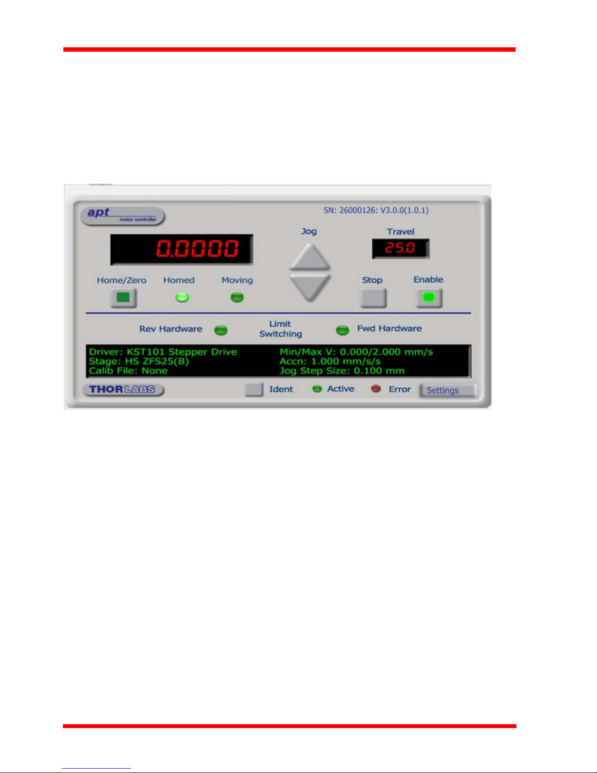
Fig. 3.5 Gui panel showing jog and ident buttons
4) Check that the actuator type associated is displayed in the GUI panel.
5) Click the ‘Ident’ button. The top panel display of the Stepper Driver K-Cube
flashes. This is useful in multi-channel systems for identifying which driver unit is
associated with which GUI.
6) Click the jog buttons on the GUI panel and check that the motor or axis connected
to the Stepper Driver K-Cube moves. The position display for the associated GUI
should increment and decrement accordingly.
18 HA0362T Rev C Jan 2017

K-Cube Stepper Motor Controller
Follow the tutorial steps described in Chapter 4 for further verification of operation.’
Note
The 'APT Config' utility can be used to set up simulated hardware
configurations and place the APT Server into simulator mode. In this way
it is possible to create any number and type of simulated (virtual)
hardware units in order to emulate a set of real hardware. This is a
particularly useful feature, des ig ne d a s an aid to applic a t io n program
development and testing. Any number of 'virtual' control units are
combined to build a model of the real system, which can then be used to
test the application software offline. If using real hardware, ensure that
Simulator Mode is disabled. If using a simulated setup, enable Simulator
Mode and set up a ‘Simulated Configuration’ - see Section 5.8. or the
APTConfig helpfile for detailed instructions.
19

Chapter 4 Standalone Operation
Stepper Motor Controller
MENU
4.1 Introduction
The Stepper Driver K-Cube has been designed specifically to operate with lower
power stepper motors such as the Thorlabs ZST series, however it can also drive a
variety of other stepper motors (15V operation) equipped with or without encoder
feedback.
The unit offers a fully featured motion control capability including velocity profile
settings, limit switch handling, homing sequences and, for more advanced operation,
adjustment of settings such as lead screw pitch and gearbox ratio, allowing support
for many different actuator configurations. These parameters can be set via the APT
Server software - see Chapter 5. Furthermore, when used with the extensive range
of Thorlabs ZST motorised opto-mechanical products, many of these parameters are
automatically set to allow “out of the box” operation with no further “tuning” required.
The following brief overview explains how the front panel controls can be used to
perform a typical series of motor moves.
In conjunction with this chapter, it also may be useful to read the background on
stepper motor operation contained in Appendix E .
4.2 Control Panel
Fig. 4.1 Front Panel Controls and Indicators
MOVE Controls - These controls allow all motor moves to be initiated.
Velocity Wheel - Used to drive the moto r at a varying speed in either forward or
reverse directions for full and easy motor control - see Section 4.3.
20

K-Cube Stepper Motor Controller
Stepper Motor Controller
At 0.0000 mm
Stopped V
Digital Display - The display shows the menu options and settings, accessed via
the menu button - see Section 4.4. When the Ident button on the associated GUI
panel is clicked, the display will flash for a short period.
MENU - used to access the settings menu - see Section 4.4. Also used to stop a
move when the stage is in motion.
4.2.1 Digital Display - Operating Mode
During normal operation, the digital display shows the current position (in millimeters
or degrees) and the current state of the motor (Stopped or Moving). If the stage being
driven has been homed, the display will also show ‘Homed’.
Fig. 4.2 Digital Display - Normal Operation
For rotation stages, the position display will be restricted to the "Equivalent Angle"
display mode (see Section 6.3.4. for more details), so the position displayed will
always be a positive number between 0 and 360 degrees. If set to T otal Angle in the
settings panel, the LED display will still show the equivalent 0 to 360° value but the
GUI screen will show the total rotation.
4.3 Velocity Wheel Operation
The velocity wheel is a sprung potentiometer, such that when released it returns to it’s
central position. In this central position the motor is stationary. Different types of move
can be initiated by the wheel, depending on its mode setting. The mo de can be set
either via the GUI Settings panel, see Section 6.3.3. or via the top panel display menu,
see Section 4.4. The various operating modes are described in Section 4.3.1. to
Section 4.3.3.
4.3.1 Homing
A ‘Home’ move is performed to establish a datum from which subsequen t absolute
position moves can be measured (see Section 5.3. and Section E.2.2. for further
information on the home position).
To initiate a ‘Home’ see Section 4.4.3.
4.3.2 Go to Position
In ‘Go To Position’ mode, two preset position values can be spe cified, such that the
motor moves to position 1 when the wheel is moved down, and to position 2 when it
21

Chapter 4
is moved up. These ‘taught’ positions can be set through the software GUI - see
Section 6.3.3. or via the display menu, see Section 4.4.7.
This mode of operation is enabled by setting the ‘Whe el Mode’ to ‘Go To Position’
through the software GUI - see Section 6.3.3. or via the display menu, see Section
4.4.5.
Note for Rotation Stage Users
If the current absolute position is outside the 0 to 360 degree range, then "go
to position" will result in a move to the correct angular position within the
same 0..360 degree full turn "segment". This means that the move will always
stay in the current full turn segment, and from this point of view it is not always
the quickest position move. For example, if you are at 350 de grees and you
enter a "go to" position of 10 degrees, the stage will rotate anticlockwise 340
degrees and not clockwise 20 degrees.
4.3.3 Jogging
The top panel wheel can also be configured to ‘jog’ the motor. This mode of operation
is enabled by setting the ‘Wheel Mode’ parameter to ‘Jogging’ thro ugh the software
GUI - see Section 6.3.3. or via the display menu, see Section 4.4.5.
Once set to this mode, the j ogging paramet ers for the wheels ar e taken from the ‘Jog ’
parameters on the ‘Move/Jogs’ settings tab - see Section 6.3.1. or via the display
menu, see Section 4.4.6.
4.3.4 Velocity Moves
Lastly, the wheel can be used to initiate a move at a spe cified vel ocity. As the wh eel
is moved away from the centre, the motor begins to move. Bidirectional control of the
motor is possible by moving the wheel in both directions. The speed of the motor
increases by discrete amounts as a function of wheel deflection, up to a maximum as
set in through the software GUI - see Section 6.3.3. or via the display menu, see
Section 4.4.4. The move stops when the wheel is returned to its centre position.
22 HA0362T Rev C Jan 2017

4.4 Settings Menu
At 0.0000 mm
Stopped V
Menu options
Use wheel
Menu options
1 Go to position
Menu options
2 Start homing
Menu options
3 Velocity
Menu options
4 Joystick mode
Menu options
5 Jog step size
Menu options
6 Teach position
Menu options
7 Brightness
Menu options
8 Disp.Timeout
Menu options
9 Disable
Menu options
10 Select Stage
MENU
4.4.1 Overview
Press the MENU button
Use the wheel to scroll through the menu options
K-Cube Stepper Motor Controller
Press the MENU button to enter a particular option
Move the stage to an absolute position - see Section 4.4.2.
Move the stage to the Home position - see Section 4.4.3.
Set the Max Velocity - see Section 4.4.4.
Set the joystick wheel mode - see Section 4.4.5.
Set the Jog Step Size - see Section 4.4.6.
Set the teach positions - see Section 4.4.7.
Set the display brightness - see Section 4.4.8.
Set the display time out period - see Section 4.4.9.
Disable the wheel - see Section 4.4.10.
Set the stage being driven - see Section 4.4.11.
23

Chapter 4
At 0.0000 mm
Stopped V
At 2.0000 mm
Stopped V
Menu options
Use wheel
Menu options
1 Go to position
P = 0.00 mm
adjust Pos
MENU
4.4.2 Menu Option - Go to position
This mode is used to move to an absolute position.
Press the MENU button, then use the wheel to scroll
through the menu options.
Press the MENU button to enter the Go to positions
option.
Use the wheel to adjust the position value, (within the
travel range for linear stages, or 0 to 360 ° for rotation
stages) then press the MENU button to store the
selection.
Note for rotation stages. If the current absolute position
is outside the 0 to 360 degree range, then "go to position"
will result in a move to the correct angular position within
the same 0..360 degree full turn "segment". This mean s
that the move will always stay in the current full turn
segment, and from this point of view it is not always the
quickest position move. For example, if you are at 350
degrees and you enter a "go to" position of 10 degrees,
the stage will rotate anticlockwise 340 degree s and not
clockwise 20 degrees.
24 HA0362T Rev C Jan 2017
The stage moves to the position entered, and the display
shows the change in position.
To stop the move, press the MENU button.

K-Cube Stepper Motor Controller
Menu options
2 Start homing
At 2.0000 mm
Stopped V
Menu options
Use wheel
MENU
At 2.0000 mm
Homing V
At 0.0000 mm
Homed Stopped V
At 0.0000 mm
Homed Stopped V
Menu options
Use wheel
Menu options
3 Velocity
1.680 mm/s
adjust MaxVel
MENU
At 0.0000 mm
Homed Stopped V
4.4.3 Menu Option - Start homing
This mode is used to home the stage.
Press the MENU button, then use the wheel to scroll
through the menu options.
Press the MENU button to enter the Star t Homing op tion.
The display shows a decreasing position count whil e the
stage is homing.
Once homing is complete, the display shows the position
at 0.0000 mm and ‘Homed’ is displayed.
To stop the move, press the MENU button.
4.4.4 Menu Option - Velocity
This mode is used to move to set the max velocity.
Press the MENU button, then use the wheel to scroll
through the menu options.
Press the MENU button to enter the Velocity option.
Use the wheel to adjust the max velocity, e.g. 0.168 mm/s,
then press the MENU button to store the setting.
Subsequent moves will be performed at the velocity
entered.
25

Chapter 4
At 0.0000 mm
Homed Stopped V
Menu options
Use wheel
Menu options
4 Joystick Mode
Velocity control
to select
MENU
Jog to positions
to select
Jogging in steps
to select
At 0.0000 mm
Homed Stopped V
At 0.0000 mm
Homed Stopped V
Homed Stopped P
Homed Stopped J
MENU
4.4.5 Menu Option - Joystick Mode
This mode is used to set the operating mode of the
joystick wheel.
Press the MENU button, then use the wheel to scroll
through the menu options
Press the MENU button to enter the Joystick mode
option. Use the wheel to scroll through the options, then
press MENU when the required option is displayed.
In Velocity control mode, deflecting the wheel starts a
move with the velocity proportional to the deflection. The
maximum velocity (i.e. velocity corresponding to the full
deflection of the joystick wheel) is set in the preceding
3 Velocity option. The move will stop when the wheel is
released.
In Jog to positions mode, deflecting the wheel starts a
move from the current position to one of the two
predefined “teach” positions. The teach positions are
specified in option 6 Teach Position.
In Jog in steps mode, deflecting the whe el initiates a jog
move, using the parameters specified by the 3 Velocity
and 5 Jog step size options. Keeping the wheel deflected
repeats the move automatically after the current move
has completed.
26 HA0362T Rev C Jan 2017
Use the wheel to display the required option, then p ress
MENU to store the selection and return to the main
display.
The selected mode is indicated at the righ t hand side of
the bottom line:
V = Velocity mode
P = Jog to position mode
J = Jog in steps mode

K-Cube Stepper Motor Controller
At 0.0000 mm
Homed Stopped V
Menu options
Use wheel
Menu options
5 Jog step size
S = 0.10 mm
adjust JogStep
MENU
At 0.0000 mm
Homed Stopped V
4.4.6 Menu Option - Jog Step Size
This mode is used to set the jog step size.
Press the MENU button, then use the wheel to scroll
through the menu options.
Press the MENU button to enter the Jog step size option.
Use the wheel to adjust the step size, e.g. 0.10 mm, then
press the MENU button to store the selection.
When Jog in steps mode is selected in the Joystick mode
option (see Section 4.4.5.), subsequent moves will be
performed at the step size entered.
27

Chapter 4
At 10.0000 mm
Homed Stopped V
Menu options
Use wheel
Menu options
6 Teach position
P1 = 10.0000 mm
num store
MENU
At 10.0000 mm
Homed Stopped V
At 5.0000 mm
Homed Stopped V
At 5.0000 mm
Homed Stopped V
Menu options
Use wheel
Menu options
6 Teach position
P2 = 5.0000 mm
num store
MENU
4.4.7 Menu Option - Teach Position
This mode is used to set the teach positions, used when the Joystick mode option is
set to Jog to positions mode - see Section 4.4.5.
To set Teach Position 1...
Move the stage to the position to use as teach position 1.
Press the MENU button, then use the wheel to scroll
through the menu options.
Press the MENU button to enter the Teach position
option.
Use the wheel to select P1, then press the MENU button
to store the current position as teach posi tion 1 an d return
to the main display.
To set Teach Position 2...
Move the stage to the position to use as teach position 2.
Press the MENU button, then use the wheel to scroll
through the menu options.
Press the MENU button to enter the Teach position
option.
Use the wheel to select P2, then press the MENU button
to store the current position as teach posi tion 2 an d return
to the main display.
When Jog to position mode is selected in the Joystick
mode option (see Section 4.4.5.), a downwards
deflection of the wheel moves the stage to position 1, and
an upwards deflection moves to position 2.
28 HA0362T Rev C Jan 2017

K-Cube Stepper Motor Controller
At 0.0000 mm
Homed Stopped V
Menu options
Use wheel
Menu options
7 Brightness
Brightness = 67
to adjust
MENU
At 0.0000 mm
Homed Stopped V
At 0.0000 mm
Homed Stopped V
Menu options
Use wheel
Menu options
8 Disp.Timeout
MENU
At 0.0000 mm
Homed Stopped V
After 2 min
to adjust
4.4.8 Menu Option - Brightness
In certain applications, it may be necessary to adjust the
brightness of the LED display. The brightness is set as a
value from 0 (Off) to 100 (brightest). The displ ay can be
turned off completely by entering a setting of zero,
however, pressing the MENU button on the top panel will
temporarily illuminate the display at its lowest brightness
setting to allow adjustments. When the display returns to
its default position display mode, it will turn off again.
Press the MENU button, then use the wheel to scroll
through the menu options.
Press the MENU button to enter the Brightness option.
Use the wheel to adjust the brightness, then press the
MENU button to store the selection and return to the main
display.
4.4.9 Menu Option - Disp.Timeout
'Burn In' of the display can occur if it remains static for a
long time. To prevent this, the display is automatically
dimmed after a specified time interval.
Press the MENU button, then use the wheel to scroll
through the menu options.
Press the MENU button to enter the Disp.Timeout option.
The time out interval is specified in minutes in the range
1 to 480.
timeout is between 1 to 10 minutes, 10 minute steps
between 10 minutes and 1 hour, and 30 minute steps
above, up to a maximum of 480 minutes. After 480
minutes there is an option for Never.
The dim level can only be adjusted via the Settings panel
- see Section 6.3.3.
The adjustment is done in steps of 1 minute if the
Press the MENU button to store the selection an d return to
the main display.
29

Chapter 4
At 0.0000 mm
Homed Stopped V
Menu options
Use wheel
Menu options
9 Disable
MENU
At 0.0000 mm
Homed Stopped V
4.4.10 Menu Option - Disable
In certain applications, it may be advantageous to disable the wheel to remove the
possibility of unwanted motion due to accidental movement of the wheel.
Press the MENU button, then use the wheel to scroll
through the menu options.
Press the MENU button to enter the Disable option.
Press the MENU button to store the selection a nd return to
the main display.
30 HA0362T Rev C Jan 2017

K-Cube Stepper Motor Controller
At 0.0000 mm
Homed Stopped V
Menu options
Use wheel
Menu options
10 Select stage
Select stage
DRV014
MENU
At 0.0000 mm
Stopped V
4.4.11 Menu Option - Select stage
Note
Later version actuators and stages have an identification eprom fitted such
that the system will recognise automatically the actuator type and install
suitable defaults at start up. In this case, the start up screens will show ‘Stage
connected xxx’ as shown in Fig. 3.4 and this menu option is not visible.
If this menu option is visible then the stage/actuator connected is not fitted
with an eprom and the stage association must be performed manually as
detailed below.
To ensure that a particular stage is driven properly by the system, a number of
parameters must first be set. These parameters relate to the physical characteristics
of the stage being driven (e.g. min and max positions, leadscrew pitch, homing
direction etc.).
Older version devices must be associated manually using the top panel menu. Once
this association has been made, the APT server applies automatically, suitable
default parameter values on boot up of the software.
Press the MENU button, then use the wheel to scroll
through the menu options.
Press the MENU button to enter the Select stage option.
Use the wheel to scroll through the options to the required
stage type. The stage types supported are:
NR360S, FW103, DRV013, DRV014, PLS2, PLS3,
ZFS25, ZFS13, ZFS06, ZST225, ZST213, ZST206,
ZST25, ZST13, ZST6
Press the MENU button to store the selection an d return to
the main display.
31

Chapter 5 PC Operation - Tutorial
5.1 Introduction
The following brief tutorial guides the user through a typical series of moves and
parameter adjustments performed using the PC based APT software. It assumes that
the unit is electrically connected as shown in Section 3.3., and that the APT Software
is already installed - see Section 3.1. For illustration purposes, it also assumes that a
ZST motor is connected to the ‘Motor’ connector on the rear panel.
5.2 Using the APT User Utility
The APT User.exe application allo ws the user to interact with any number of APT
hardware control units connected to the PC USB Bus (or simulated via the APTConfig
utility). This program allows multiple graphical instrumen t panels to be displayed so
that multiple APT units can be controlled. All basic operating pa rameters can be set
through this program, and all basic operations (such as motor moves) can be initiated.
Hardware configurations and parameter settings can be saved, which simplifies
system set up whenever APT User is run up.
1) If required, perform the stage association as detailed in Section 4.4.11.
2) Run the APT User program - Start/Programs/Thorlabs/APT/APT User.
32
Fig. 5.1 Typical APT User Screen

K-Cube Stepper Motor Controller
3) The actuator type recognised/associated is displayed in the ‘Settings’ window.
See Section 5.11. and Section 6.3. for further details on th e parameter values
shown in the ‘Settings’ display.
Fig. 5.2 Stepper Driver K-Cube Software GUI
The APT User utility will be used throughout the rest of this tutorial to interface with
the Stepper Driver K-Cube.
33

Chapter 5
5.3 Homing Motors
Homing the motor moves the actuator to the home limit switch and resets the internal
position counter to zero. The limit switch provides a fixed datum that can be found
after the system has been powered up.
Fig. 5.3 Stepper Driver K-Cube GUI
1) Click the ‘Home’ button. Notice that the led in the button lights to indicate that
homing is in progress and the displayed position counts down to 000.0 00, i.e the
home position.
Note
Homing can also be performed by holding down both front panel bu ttons
for around 2 seconds.
2) When homing is complete, the ‘Homed’ LED is lit as shown above.
See Appendix E , Section E.2.2. for background information on the home position.
34 HA0362T Rev C Jan 2017

K-Cube Stepper Motor Controller
5.4 Moving to an Absolute Position
Absolute moves are measured in real world units (e.g. millimetres), relative to the
Home position.
1) Click the position display.
Fig. 5.4 Absolute Position Popup Window
2) Enter 0.3589 into the pop up window
3) Click ‘OK’. Notice that the position display counts up to 0.35900 to indicate a move
to the absolute position entered.
35

Chapter 5
5.5 Changing Motor Parameters
Moves are performed using a trapezoidal velocity profile (see Appendix E , Section
E.1.3.). The velocity settings relate to the maximum velocities at which a move is
performed, and the acceleration at which the motor speeds up from zero to maximum
velocity.
1) On the GUI panel, click the ‘Settings’ button (bottom right hand corner of the
display) to show the Settings panel.
Fig. 5.5 Settings Panel - Move/Jogs Tab
2) Select the Move/Jogs tab as shown in Fig. 5.5.
3) In the ‘Moves’ field, enter para me te r val u es as follows:
‘Max. Vel’ - ‘4’
‘Accn/Dec’ - ‘1.5’
Note
In current versions of software, the ‘Min Vel’ parameter is locked at zero
and cannot be adjusted.
4) Click ‘OK’ to save the settings and close the window.
5) Any further moves initiated will now be perfo rmed at a maximum velocity of 4.0
mm per second, with an acceleration of 1.5 mm/sec/sec.
36 HA0362T Rev C Jan 2017

K-Cube Stepper Motor Controller
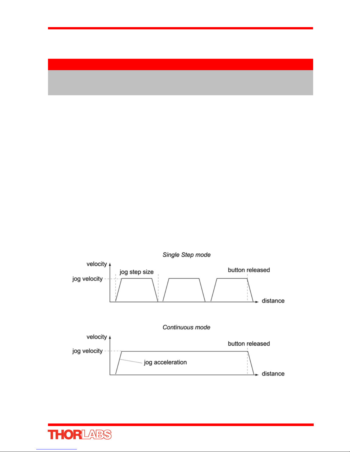
5.6 Jogging
During PC operation, the motor actuators are jogged using the GUI panel arrow keys.
There are two jogging modes available, ‘Single Step’ and ‘Continuous’. In ‘Single
Step’ mode, the motor moves by the step size specified in the Step Distance
parameter. If the jog key is held down, single step jogging is repeated until the button
is released - see Fig. 6.3. In ‘Continuous’ mode, the motor actuator will accelerate and
move at the jog velocity while the button is held down.
1) On the GUI panel, click the ‘Settings’ button to display the Settings panel.
Fig. 5.6 Settings Panel - Move/Jogs Tab
2) Select the Move/Jogs tab as shown in Fig. 5.6.
3) In the ‘Jogs’ field, enter parameter values as follows:
Velocity Profile
‘Max. Vel’ - ‘1’
‘Accn/Dec’ - ‘0.5’
Note
In current versions of s oftwa re, the ‘Min Vel’ parameter is locked at zero
and cannot be adjusted.
Operating Modes
‘Jogging’ - ‘Single Step’
‘Stopping’ - ‘Profiled’
‘Step Distance’ - ‘0.5’
4) Click ‘OK’ to save the settings and close the window.
5) Click the Jog Arrows on the GUI panel to jog the motor. Notice that the position
display increments 0.5 every time the button is clicked.
37
Chapter 5
5.7 Stopping the Stage
The drive channel is enabled and disabled by clicking the ‘Enable’ button on the GUI
panel. The green indicator in the button center is lit when the drive channel is enabled.
Disabling the channel removes the drive power.
During operation, the stage can be stopped at an y time by clicking the ‘Stop’ button
on the GUI panel. Using this button does not remove power to the drive channel.
.
Fig. 5.7 APT GUI User Screen
38 HA0362T Rev C Jan 2017

K-Cube Stepper Motor Controller
5.8 Graphical Control Of Motor Positions (Point and Move)
The GUI panel display can be changed to a graphical display, showing the position of
the motor channel(s). Moves to absolute positions can then be initiated by positioning
the mouse within the display and clicking.
To change the panel view to graphical view, right click in the screen and select
‘Graphical View’.
Fig. 5.8 Stepper Driver K-Cube GUI Panel - Graphical View
Consider the display shown above for an Stepper Driver K-Cube .
The right hand display shows the channel and motor unit parameters; i.e. controll er
unit type and serial number, associated stage and actuator type, minimum and
maximum positions, current position, units per grid divi sion and cursor position. All
units are displayed in real world units, either millimetres or degrees.
Note
For single channel units such as the Stepper Driver K-Cube, the Channel
2 parameters are greyed out.
The left hand display shows a circle, which represents the current position of the
motor associated with the specified controller (abso lute position data is displayed in
the 'Chan Pos' field).
The vertical divisions relate to the travel of the stage/actuator associated with the
Stepper Driver K-Cube (the stage/actuator is selected in the ‘APT Config’ utility). For
example, the screen shot above shows the parameters for a 25mm travel ZFS25(B)
motor actuator. The graph shows 10 divisions in the X axis, which relates to 2.5 mm
of travel per division (25mm in total).
The graphical panel has two modes of operation, ‘Jog’ and ‘Move’, which are selected
by clicking the buttons at the bottom right of the screen.
39

Chapter 5
Move Mode
When ‘Move’ is selected, the motors move to an absolute position which corresponds
to the position of the cursor within the screen.
To specify a move:
1) Position the mouse within the window. For reference, the absolute motor position
values associated with the mouse position is displayed in the 'Cursor Position
field.
2) Click the left hand mouse button to initiate the move.
Jog Mode
When ‘Jogging’ mode is selected, the motors are jogged each time the left mouse
button is clicked.
The Jog direction corresponds to the position of the cursor relative to the circle
(current motor position), e.g. if the cursor is to the left of the circle the motor will jog
left. The Jog Step size is that selected in the Settings panel - see Section 6.3.
Stop
To stop the move at any time, click the ‘Stop’ button.
Returning to Panel View
To return to panel view, right click in the graphical panel and select ‘Panel View’.
40 HA0362T Rev C Jan 2017

K-Cube Stepper Motor Controller
5.9 Setting Move Sequences
This section explains how to set move sequences, allow ing several positions to be
visited without user intervention.
For details on moving to absolute positi ons initiated by a mouse click – see Section
5.8.
1) From the Motor GUI Panel, select 'Move Sequencer' tab to display the Move
Sequencer window.
Fig. 5.9 Move Sequencer Window
2) Right click, in the move data field to display the pop up menu.
Fig. 5.10 Move Sequencer Pop Up Menu
41

Chapter 5
3) Select 'New' to display the 'Move Editor' panel.
Fig. 5.11 Move Editor Window
Move data is entered/displa ye d as follows:
Dist/Pos: - the distance to move from the current position (if 'Relative' is selected)
or the position to move to (if 'Absolute' is selected).
Dwell Time: - after the move is performed, the system can be set to wait for a
specified time before performing the next move in the sequence. The Dwell time is the
time to wait (in milliseconds).
Return - if checked, the system will move to th e position specified in the Dist/Pos field,
wait for the specified Dwell time, and then return to the original position.
4) Min Vel: Acc: and Max Vel: - the velocity profile parameters for the move.
Note
In current versions of software, the ‘Min Vel’ parameter is locked at zero
and cannot be adjusted.
The motor accelerates at the rate set in the Acc field up to the speed set in the Max
Vel field. As the destination approaches, the moto r decelerates again to ensure that
there is no overshoot of the position.
42 HA0362T Rev C Jan 2017

K-Cube Stepper Motor Controller
5) Enter the required move data into the Move Editor and click OK. The move data
is displayed in the main window as shown below.
Fig. 5.12 Main Window with Move Data
6) Repeat step 4 as necessary to build a sequence of moves. Move data can be
copied, deleted, cut/pasted and edited by right clicking the data line(s) and
selecting the appropriate option in the pop up menu (shown below).
Fig. 5.13 Pop Up Options
7) To run a single line of data, right click the appropria te data and select 'Run' from
the pop up menu (shown above).
8) To run the entire sequence, click the 'Run' button (shown below). A Home move
can also be performed from this panel by clicking the ‘Home’ button.
Fig. 5.14 Home and Run Buttons
9) To save data to a file, or load data from a previously saved file, click the ‘Save’ or
‘Load’ button and browse to the required location.
43

Chapter 5
5.10 Creating a Simulated Configuration Using APT Config
The 'APT Config' utility can be used to set up simulated hardware configurations and
place the APT Server into simulator mode. In this way it is possible to cre ate any
number and type of simulated (virtual) hardware units in order to emulate a set of real
hardware. This is a particularly useful feature, designed as an aid learning how to use
the APT software and as an aid to developing custom software applications ‘offline’.
Any number of 'virtual' control units can be combined to emulate a colection of
physical hardware units For example, an application pr ogram can be written, then
tested and debugged remotely, before running with the hardware.
To create a simulated configuration proceed as follows:
1) Run the APT Config utility - Start/All Programs/Thorlabs/APT/APT Config.
2) Click the 'Simulator Configuration' tab.
Fig. 5.15 APT Configuration Utility - Simulator Configuration Tab
3) Enter ‘LAB1’ in the Configuration Names field.
44 HA0362T Rev C Jan 2017

K-Cube Stepper Motor Controller
4) In the 'Simulator' field, check the ‘Enable Simulator Mode’ box. The name of the
most recently used configuration file is displayed in the 'Current Configuration'
window.
5) In the ‘Control Unit’ field, select ‘1 Ch Stepper Driver K-Cube (KST101)’.
45

Chapter 5
6) In the ‘Enter 6 digit serial number’ field, enter the serial number of your stepper
drive unit.
Note
Each physical APT hardware unit is factory programmed with a unique 8
digit serial number. In order to simulate a set of ‘real’ hardware the Config
utility allows an 8 digit serial number to be associated with each
simulated unit. It is good practice when creating simulated
configurations for software development purposes to use the same serial
numbers as any real hardware units that will be used. Altho ugh serial
numbers are 8 digits (as displayed in the ‘Load Configuration Details’
window), the first two digits are added automatically and identify the type
of control unit.
The prefixed digits relating to the Stepper Driver K-Cube are:
26xxxxxx - 1 Ch Stepper Drive K-Cube
7) Click the 'Add' button.
8) Repeat items (1) to (7) as required. (A unit can be removed from the configuration
by selecting it in the 'Loaded Configuration Details' window and clicking the
'Remove' button or by right clicking it and selecting the ' Remove' option from the
pop up window).
9) Click 'Save'.
10)Click 'Set As Current' to use the configuration.
46 HA0362T Rev C Jan 2017

K-Cube Stepper Motor Controller
5.11 Stage/Axis Tab
This tab contains a number of parameters which are related to the physical
characteristics of the particular stage or actuator being driven. They need to be set
accordingly such that a particular stage is driven properly by the system.
Fig. 5.16 Stage/Axis Tab
These parameters were set automatically when the ZST6 actuator was selected using
the APTConfig utility in Section 3.5. The APT server auto matically applied suitable
defaults for the parameters on this tab during boot up of any client software such as
APTUser. These parameters should not be altered for pre-defi ned Thorlabs stages
and actuators selected using APT Config, as it may adversely affect the performance
of the stage.
For third party stage types not available using the APT Config utility, these stage
details must be entered manually.
Individual parameters are described in Section 6.3.
47

Chapter 6 Software Reference
6.1 Introduction
This chapter gives an explanation of the parameters and settings accessed from the
APT software running on a PC. For information on the methods and properties which
can be called via a programming interface, see Appendix D .
6.2 GUI Panel
The following screen shot shows the graphical user interface (GUI) displa yed when
accessing the Stepper Driver K-Cube using the APTUser utility.
Fig. 6.1 Stepper Driver K-Cube Software GUI
The serial number of the Stepper Driver K-Cube associated with the GUI
panel, the APT server version number, and the version number (in
brackets) of the embedded software running on the unit, are displayed in
the top right hand corner. This in formation should always be provided
when requesting customer support.
Jog - used to increment or decrement the motor position. When the button is clicked,
the motor is driven in the selected direction at the jog velocity one step per click. The
step size and jog velocity parameters are set in the 'Settings' panel (see Section 6.3.).
48
Note

K-Cube Stepper Motor Controller
Travel - displays the range of travel (in millimeters or de grees) of the motor.
Moving - lit when the motor is in motion.
Enable - applies power to the motor. With the motor enabled, the LED in the button
is lit.
Digital display - shows the position (in millimetres or degrees) of the motor. The
motor must be 'Homed' before the display will show a meaningful value, (i.e. the
displayed position is relative to a physical datum, the limit switch).
Home - sends the motor to its 'Home' position - see Appendix E Section E.2.2. The
LED in the button is lit while the motor is homing.
Homed - lit when the motor has previously been 'Homed' (since power up).
Stop - halts the movement of the motor.
Limit switches - the LEDs are lit when the associated limit switch has been activated
- see Appendix E Section E.2.3. for further details on limit switches.
Settings display - shows the following user specified settings:
Driver - the type of control unit associated with the specified channel.
Stage - the stage type and axis associated with the specified channel.
Note. By default, the software associates a ZST6 type actu ator, unless the user h as
used the APTConfig utility to associate a particular stage.
Calib File - the calibration file associated with the specified channel.
See the APTConfig utility helpfile for more details on assigning a nd using cal ibration
files.
Min/Max V - the minimum veloci ty at which a move is initiated, and the maximum
velocity at which the move is performed. Values are displayed in real world units (mm/
s or degrees/s), and can be set via the 'Settings' panel (see Section 6.3.).
Accn - the rate at which the velocity climbs to, and slows from, maximum velocity,
displayed in real world units (mm/s/s or degrees/s/s). The acceleration can be set via
the 'Settings' panel (see Section 6.3.) and is used in conjunction w ith the Min/Max
velocity settings to determine the velocity profil e of a motor move. See Appendix E
Section E.1.3. for more information on velocity profiles.
Jog Step Size - the size of step (in mm or degrees) taken when the jog signal is
initiated. The step size can be set either via the Settings panel or by calling the
SetJogStepSize method.
Settings button - Displays the 'Settings' panel, which allows the operating
parameters to be entered for the motor drive - see Section 6.3.
Ident - when this button is pressed, the Channel LED on the front panel of the
associated hardware unit will flash for a short period.
Active - lit when the unit is operating normally and no error condition exists.
Error - lit when a fault condition occurs.
49

Chapter 6
6.3 Settings Panel
When the 'Settings' button on the GUI panel is clicked, the 'Settings' window is
displayed. This panel allows motor operation parameters such as move/jog velocities,
and stage/axis information to be modified. Note that all of these parameters have
programmable equivalents accessible through the ActiveX me thods and properties
on this Control (refer to the Programming Guide in the APTServer helpfile for further
details and to Section 2.3.4. for an overview of the APT ActiveX controls).
6.3.1 Moves/Jogs Tab
Fig. 6.2 Stepper Driver K-Cube - Move/Jog Settings
Moves - Velocity Profile
Moves can be initiated via the GUI panel, by using the velocity wheel (see Section
4.3.) or by entering a position value after clicking on the position display box (see
Section 5.4.). The following settings determine the velocity profile of such moves, and
are specified in real world units, millimetres or degrees.
Note
The minimum velocity is locked at zero and cannot be adjusted.
MaxVel - the maximum velocity at which to perform a move.
50 HA0362T Rev C Jan 2017
K-Cube Stepper Motor Controller
Accn/Dec - the rate at which the velocity climbs from zero to maximum, and slows
from maximum to zero.
Note
Under certain velocity parameter and move distan ce conditions, the
maximum velocity may never be reached (i.e. the move comprises an
acceleration and deceleration phase only).
Jogs
Jogs are initiated by using the ‘Jog’ keys on the GUI panel (see Section 5.6.), or the
Jog Buttons on the front panel of the unit.
Velocity Profile (specified in real world units, millimetres or degrees)
MaxVel - the maximum velocity at which to perform a jog
Accn/Dec - the rate at which the velocity climbs from minimum to maximum, and
slows from maximum to minimum.
Operating Modes
Jogging - The way in which the motor moves when a jog command is received (i.e.
front panel button pressed or GUI panel button clicked).
There are two jogging modes available, ‘Single Step’ and ‘Continuous’. In ‘Single
Step’ mode, the motor moves by the step size specified in the Step Distance
parameter. If the jog key is held down, single step jogging is repeated until the button
is released - see Fig. 6.3. In ‘Continuous’ mode, the motor actuator will accelerate and
move at the jog velocity while the button is held down..
Single Step - the motor moves by the step size specified in the Step Distance
parameter.
Fig. 6.3 Jog Modes
51

Chapter 6
Continuous - the motor continues to move until the jog signal is removed (i.e. jog
button is released).
Stopping - the way in which the jog motion stops when the demand is removed.
Immediate - the motor stops quickly, in a non-profiled manner
Profiled - the motor stops in a profiled manner using the jog Velocity Profile
parameters set above.
Step Distance - The distance to move when a jog command is initiated. The step size
is specified in real world units (mm or degrees dependent upon the stage).
Backlash Correction - The system compensates for lead screw backlash during
reverse direction moves, by moving passed the demanded position by a sp ecified
amount, and then reversing. This ensures that positions are alwa ys approach ed in a
forward direction. The Backlash Correction Distance is specified in real world un its
(millimeters or degrees). To remove backlash correction, this value should be set to
zero.
Position Profiling
To prevent the motor from stall ing, it must be ramped up gradually to its maximum
velocity. Certain limits to velocity and acceleration result from the torq ue and speed
limits of the motor, and the inertia and friction of the parts it drives.
The system incorporates a trajectory generator, which performs calculations to
determine the instantaneous position, velocity and acceleration of each axis at any
given moment. During a motion profile, these value s wil l chang e continuously. Once
the move is complete, these parameters will then remain unchanged until the next
move begins.
The specific move profile created by the system depends on several factors, such as
the profile mode and profile parameters presently selected, and other conditions such
as whether a motion stop has been requested.
Bow Index – This field is used to set the profile mode to either Trapezoidal or S-curve.
A Bow Index of ‘0’ selects a trapezoidal profile. An index value of ‘1’ to ‘18’ selects an
S-curve profile. In either case, the velocity and acceleration of the profile are specified
using the Velocity Profile parameters on the Moves/Jogs tab.
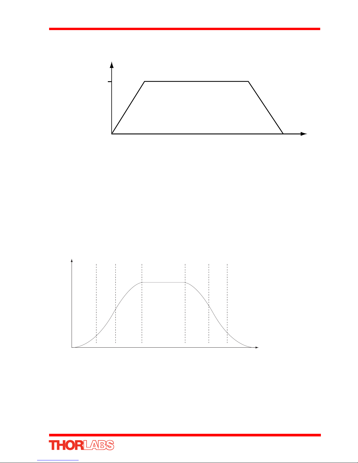
The Trapezoidal profile is a standard, symmetrical acceleration/deceleration motion
curve, in which the start velocity is always zero. This profile is selected when the Bow
Index field is set to ‘0’.
In a typical trapezoidal velocity profile, (see Fig. 6.4.), the stage is ramped at
acceleration ‘a’ to a maximum velocity ‘v’. As the destination is approached, the stage
52 HA0362T Rev C Jan 2017
K-Cube Stepper Motor Controller
velocity
maximum
velocity (v)
time
acceleration (slope) a
BI BI
A
D
-BI -BI
V
Velocity
12 3 4 56 7
A - acceleration
D - deceleration
V - velocity
BI - bow index
is decelerated at ‘a’ so that the final position is approached slowly in a controlled
manner.
Fig. 6.4 Graph of a trapezoidal velocity profile
The S-curve profi le is a trapezoidal curve with an additi onal 'Bow Value' parameter,
which limits the rate of change of acceleration and smooths out the contours of the
3
motion profile. The Bow Value is applied in mm/s
and is derived from the Bow Index
field as follows:
Bow Value = 2
(Bow Index -1)
within the range 1 to 262144 (Bow Index 1 to 18).
In this profile mode, the acceleration increases gradually from 0 to the specified
acceleration value, then decreas es at the same rate until it reaches 0 again at the
specified velocity. The same sequence in reverse brings the axis to a stop at the
programmed destina ti o n po si ti on.
Example
Fig. 6.5 Typical S-Curve Profile
The figure above shows a typical S-curve profi le. In segment (1), the S-curve profile
drives the axis at the specified Bow Index (BI) until the maximum acceleration (A) is
reached. The axis continues to accelerate linearly (Bow Index = 0) through segment
(2). The profile then applies the negative value of Bow Index to reduce the
acceleration to 0 during segment (3). The axis is now at the maximum velocity (V), at
which it continues through segment (4). The profile then decelerates in a similar
53

Chapter 6
manner to the acceleration phase, using the Bow Index to reach the maximum
deceleration (D) and then bring the axis to a stop at the destination.
Note
The higher the Bow Index, then the shorter the BI phases of the curve, and
the steeper the acceleration and deceleration phases. High values of Bow
Index may cause a move to overshoot or may result in instability.
Persist Settings to Hardware - Many of the parameters that can be set for the
Stepper Driver K-Cube can be stored (persisted) within the unit itself, such that when
the unit is next powered up these settings are applied automatically. This is
particularly important when the driver is being used manually in the absence of a PC
and USB link. The Velocity Profile and Jogging parameters described previo usly are
good examples of settings that can be altered and then persisted in the driver for use
in absence of a PC. To save the settings to hardware, check the ‘Persist Settings to
Hardware’ checkbox before clicking the ‘OK button.
Caution
The ‘Persist Settings’ functionality is provided to simplify use of the unit
in the absence of a PC. When the unit is connected to a PC and is
operated via APTUser, the default APTServer settings will be loaded at
boot up, even if the ‘Persist Settings’ option has been checked.
54 HA0362T Rev C Jan 2017

6.3.2 Stage/Axis Tab
K-Cube Stepper Motor Controller
Fig. 6.6 Stepper Driver K-Cube - Stage/Axis Settings
Note
This tab contains a number of parameters which are related to the physical
characteristics of the particular stage being driven. They need to be set
accordingly such that a particular stage is driven properly by the system.
For Thorlabs stages, the APT Config utility can be used to associate a specific
stage and axis type with the motor channel (refer to the APT Config helpfile
for further details on how to associate a stage and axis). Once this association
has been made, the APT server will automatically apply suitable defaults for
the parameters on this tab during boot up of the software. These parameters
should not be altered for pre-defined Thorlabs stages selected using APT
Config, as it may adversely affect the performance of the stage.
For custom stage types not available using the APT Config utility, the stage
details must be entered manually. Individual parameters are described in the
following paragraphs.
Stage and Axis Ty pe - For Thorlabs stages, the stage type is displayed automatically
once the axis has been associated using the APTConfig utility. For third party stages,
the display shows ‘Unknown’.
Extreme care must be taken when modifying the stage related settings that
follow. Some settings are self consistent with respect to each other, and illegal
combinations of settings can result in incorrect operation of the physical
motor/stage combination being driven. Consult Thorlabs for advice on settings
for stage/actuator types that are not selectable via the APTConfig utility.
Caution
55

Chapter 6
Min Pos - the stage/actuator minimum position (typically zero).
Max Pos - the stage/actuator maximum position.
Pitch - the pitch of the motor lead screw (i.e. the distance travelled (in mm or degrees)
per revolution of the leadscrew).
Units - the ‘real world’ positioning units (mm or degrees).
Homing
When homing, a stage typically moves in the reverse direction, (i.e. towards the
reverse limit switch). The following settings allow support for stages with both Forward
and Reverse limits.
Note
Typically, the following two parameters are set the same, i.e. both
Forward or both Reverse.
Direction - the direction sense to move when homing, either Forward or Reverse.
Limit Switch - The hardware limit switch associated with the home position, either
Forward HW or Reverse HW.
Zero Offset - the distance offset (in mm or degrees) from the limit switch to the Home
position.
Velocity - the maximum velocity at which the motors move when Homing.
Caution
The homing velocity should not be increased above the 250 µm/s factory
setting as this may damage the limit switches.
For further information on the home position, see Section E.2.2.
Hardware Limit Switches
Note
The minimum velocity and acceleration/deceleration parameters for a
home move are taken from the existing move velocity profile parameters.
The operation of the limit switches is inherent in the design of the associated stage or
actuator. The following parameters notify the system to the action of the switches
when contact is made. Select Rev Switch or Fwd Switch as required, then select the
relevant operation.
Switch Makes - The switch closes on contact
Switch Breaks - The switch opens on contact
Ignore/Absent - The switch is missing, or should be ignored.
56 HA0362T Rev C Jan 2017

K-Cube Stepper Motor Controller
Motor
These parameters are used to set the 'resolution' characteristics of the stepper motor
connected to the selected channel. The reso lution of the motor, combined with other
characteristics (such as lead screw pitch) of the associated actuator or stage,
determines the overall resolution.
Steps Per Rev - The number of full steps per revolution of the stepper motor
(minimum '1', maximum '10000').
Note
The Gearbox Ratio parameter is applicable only to motors fitted with a
gearbox.
Gearbox Ratio - The ratio of the gearbox. For example, if the gearbox has a reduction
ratio of X:1 (i.e. every 1 turn at the output of the gearbox requires X turns of the motor
shaft) then the Gearbox Ratio value is set to X. (minimum '1', maximum '1000').
Note
The ‘Steps Per Rev’ and ‘Gearbox Ratio’ parameters, together with the
‘Pitch’ and ‘Units’ parameters are used to calculate the calibration factor
for use when converting real world units to microsteps. However, the
‘Steps Per Rev’ parameter is entered as full steps, not microsteps. The
system automatically applies a factor of 2048 microsteps per full step.
The majority of Thorlabs stepper motor actuators have 200 full steps per
rev and no gearbox fitted. For these motors the Steps Per Rev and
Gearbox Ratio parameters have values of 200 and 1 respectively. As an
exception to this, the ZST family of actuators use 24 steps per rev stepper
motors fitted with a 41:1 reduction gearbox. In this case, the Steps Per
Rev and Gearbox Ratio should be set to '24' and '41' respectively. The
equivalent calibration constant is then calculated as:
24 x 2048 x 41 = 2,015,232
24 steps per revolution
2048 microsteps per full step
41:1 reduction gearbox
1.0 mm lead screw pitch
Persist Settings to Hardware - Many of the parameters that can be set for the
Stepper Driver K-Cube can be stored (persisted) within the unit itself, such that when
the unit is next powered up these settings are applied automatically. This is
particularly important when the driver is being used manually in the absence of a PC
and USB link. The homing parameters and limit switch settings described previou sly
are good examples of settings that can be altered and then persisted in the driver for
57

Chapter 6
use in absence of a PC. To save the settings to hardware, check the ‘Persist Settings
to Hardware’ checkbox before clicking the ‘OK button.
Caution
The ‘Persist Settings’ functionality is provided to simplify use of the unit
in the absence of a PC. When the unit is connected to a PC and is
operated via APTUser, the default APTServer settings will be loaded at
boot up, even if the ‘Persist Settings’ option has been checked.
6.3.3 Panel/Triggering Tab
Fig. 6.7 Stepper Driver K-Cube - Advanced Settings
Adjustment Wheel Settings
The velocity wheel is sprung such that when released it returns to it’s central position.
In this central position the motor is stationary. As the wheel is moved away from the
center, the motor begins to move; the speed of this movement increases as the wheel
deflection is increased. Bidirectional control of motor moves is possible by moving the
wheel in both directions.
Wheel Mode
Velocity Control - Deflecting the wheel starts a move with the velocity proportional
to the deflection. The maximum velocity (i.e. velocity corresponding to the full
deflection of the joystick wheel) and acceleration a re set in the Max Wheel Vel.
and Wheel Accn. parameters.
Position Jogging - Deflecting the wheel initiates a jog move, using the parameters
specified by the Move/Jogs tab. Keeping the wheel deflected repeats the move
automatically after the current move has completed.
Go To Position - Deflecting the wheel starts a move from the current position to
one of the two predefined “teach” positio ns. The teach positions are specified in
58 HA0362T Rev C Jan 2017

K-Cube Stepper Motor Controller
the Preset Pos. 1 and Preset Pos. 2 parameters, and are measured in number of
steps from the home position.
Wheel Direction
The direction of a move initiated by the velocity wheel is specified as follows:
Disabled - The wheel is disabled to remove any unwanted motion due to
accidental movement of the wheel.
Direction Sense Positive - Upwards rotation of the wheel results in a positive
motion (i.e. increased position count).
Note. The following option applies only when the Wheel Mode is set to Velocity
Control. If set to Position Jogging or Go to Position Mode, the followin g option is
ignored.
Direction Sense Negative - Upwards rotation of the wheel re sults in a negative
motion (i.e. decreased position count).
Display Brightness
In certain applications, it may be necessary to adjust the brightness of the LED display
on the top of the unit. The brightness is set in the Active Level parameter, as a value
from 0 (Off) to 100 (brightest). The display can be turned off completely by entering a
setting of zero, however, pressing the MENU button on the top panel will temporarily
illuminate the display at its lowest brightn ess setting to a llow ad justments. When the
display returns to its default position display mode, it will turn off again.
Furthermore, 'Burn In' of the display can occur if it remains static for a long time. To
prevent this, the display is automatically dimmed after the time interval specified in the
Timeout (min) parameter has elapsed. The time interval is specified in minutes in the
range 0 (never dimmed) to 480. The dim level is set in the Idle Level parameter, as a
value from 0 (Off) to 10 (brightest) but is also limited by the Active Value parameter if
this is lower.
Persist Settings to Hardware - Many of the parameters that can be set for the DC
Driver K-Cube can be stored (persisted) within the unit itself, such that when the unit
is next powered up these settings are applied automatically. This is particularly
important when the driver is being used manually in the absence of a PC and USB
link. The wheel, and trigger parameters described here are good examples of settings
that can be altered and then persisted in the driver for use in absence of a PC. To
save the settings to hardware, check the ‘Persist Settings to Hardware’ checkbox
before clicking the ‘OK button.
The ‘Persist Settings’ functionality is provided to simplify use of the unit
in the absence of a PC. When the unit is connected to a PC and is
operated via APTUser, the default APTServer settings will be loaded at
boot up, even if the ‘Persist Settings’ option has been checked.
Caution
59

Chapter 6
Triggering Introduction
The K-Cube motor controllers have two bidirectional trigger ports (TRIG1 and TRIG2)
that can be used to read an external logic signal o r output a logic level to control
external equipment. Either of them can be independently configured as an input or an
output and the active logic state can be selected High or Low to suit the requirements
of the application. Electrically the ports output 5 Volt logic sign als and are designed
to be driven from a 5 Volt logic.
When the port is used in the input mode, the logic levels are T TL compatible, i.e. a
voltage level less than 0.8 Volt will be recognised as a logic LOW and a level greater
than 2.4 Volt as a logic HIGH. The input contains a weak pull-up, so the state of the input
with nothing connected will default to a logic HIGH. The weak pull-up feature allows a
passive device, such as a mechanical switch to be connected directly to the input.
When the port is used as an ou tput it provides a push -pull drive of 5 Volts, with the
maximum current limited to approximately 8 mA. The current limit prevents damage
when the output is accidentally shorted to ground or driven to the opposite logic state
by external circuity.
Warning: do not drive the TRIG ports fr om any voltage source that can p roduce an
output in excess of the normal 0 to 5 Volt logic level range. In any case the voltage at
the TRIG ports must be limited to -0.25 to +5.25 Volts.
Input Trigger Modes
When configured as an input, the TRIG ports can be used as a general purpose digital
input, or for triggering a relative, absolute or home move. When used for triggering a
move, the port is edge sensitive. In other words, it has to see a transition from the
inactive to the active logic state (Low->High or High->Low) for the trigger inpu t to be
recognized. For the same reason a sustained logic level will not trigger repeated
moves. The trigger input has to return to its inactive state first in order to start the next
trigger. The mode is set in the Trig 1 Mode and Trig 2 Mode parameters as follows:
Disabled - The trigger IO is disabled
Digital Input - General purpose logic input (read through status bits using the
LLGetStatusBits method).
Trig In Rel. Move - Input trigger for relative move.
Trig In Abs. Move - Input trigger for absolute move.
Trig In Home - Input trigger for home move.
When the trigger mode is selected to Trig In Rel Move or Trig In Abs Move, the relative
distance or absolute position to move, can be entere d in the Rel ative Move Dist and
Absolute Move Pos. parameters.
60 HA0362T Rev C Jan 2017

K-Cube Stepper Motor Controller
Output Trigger Modes
When the Trig 1 Mode and Trig 2 Mode parameters are configured as outputs, the
TRIG ports can be used as a general purpose digital output, or to indicate motion
status or to produce a trigger pulse at configurable positions as follows:
Digital Output - General purpose logic output (set using the LLSetGetDigOPs
method).
Trig Out In Motion - Trigger output active (level) when motor 'in motion'. The output
trigger goes high (5V) or low (0V) (as set in the Trig 1. Polarity and Trig. 2 Polarity
parameters) when the stage is in motion.
Trig Out Max Vel - Trigger output active (level) when motor at 'max velocity'.
Trig Out Pos. Steps Fwd - Trigger output active (pulsed) at pre-defined positions
moving forward. Only one Trigger port at a time can be set to this mode. See
Trigger Out Position Steps for further details.
Trig Out Pos. Steps Rev - Trigger output active (pu lsed) at pre-defined positio ns
moving backwards. Only one Trigger port at a time can be set to th is mode. See
Trigger Out Position Steps for further details.
Trig Out Pos. Steps Both - Trigger output active (pulsed) at pre-defined positions
moving forwards and backward. Only one Trigger port at a time can be set to this
mode. See Trigger Out Position Steps for further details.
Trigger Out Position Steps
Note
If the trigger mode is not set to one of the three position modes described
previously, then the following parameters are not applicable and will be
greyed out.
In the last three modes described above, the controller outputs a configurable number
of pulses (set in the Num. Pulses Fwd and Num. Pulses Rev parameters), of
configurable width (Trig Pulse Width), when the actual position of the stage matches
the position values configured as the Start Position and Positio n Interval (Start Pos.
Fwd and Start Pos. Rev. These modes allow external equipment to be triggered at
exact position values.
Using the last three modes, position triggering can be configured to be unidirectional
(Trig Out Pos. Steps Fwd or Trig Out Pos. Steps Rev) or bidirectional (Trig Out Pos.
Steps Both). In bidirectional mode the forward and reverse pulse sequen ces can be
configured separately. A cycle count setting (Num. of Move Cycles) allows the uni- or
bidirectional position triggering sequence to be repeated a number of times.
61

Chapter 6
Time
Trig Voltage
Pos1 Fwd
Pos2 Fwd
Pos1 Rev
10 mm
15 mm
12 mm
5V
0V
StartPosFwd
StartPosRev
PosIntervalFwd
Fig. 6.8 Position Steps Triggering
Example for a move from 0 to 20 mm and back.
In forward direction: The first trigger puls e occurs at 10 mm (StartPosFwd), the next
trigger pulse occurs after another 5 mm (PosIntervalFwd), the stage then moves to 20
mm.
In reverse direction: The next trigger occurs when the stage gets to 12 mm.
Note that position triggering can only be used on one TRIG port at a time, as there is
only one set of position trigger parameters.
Triggering Polarity
The polarity of the trigger pulse is specified in the Trig. 1 Polarity and Trig 2 Polarity
parameters as follows:
Active is High - The active state of the trigger port is logic HIGH 5V (trigger input
and output on a rising edge).
Active is Low - The active state of the tri gger port is logic LOW 0V (trigger input
and output on a falling edge).
62 HA0362T Rev C Jan 2017

6.3.4 Rotation StagesTab
K-Cube Stepper Motor Controller
Absolute Position Reporting Mode
This setting relates to the way in which th e angular position is displayed on the GUI
panel. There are two options:
Equivalent Angle 0 to 360 degrees – The maximum displayed position is 359.99°.
If a stage is driven past the 360° rotation point, the display re verts back to zero
and counts up to 360° again.
Total Angle (360 x Num Revs + Angular Offset) – The total angular rota tion is
displayed, e.g. for a movement of two full rotations plus 10°, the display will show
730°.
Note. The following parameters are applicable only if the Absolute Position
Reporting Mode is set to ‘Equivalent Angle 0 to 360 degrees’.
Panel Display Rotation Move Mode
This setting specifies the move direction. There are three options:
Rotate Positive – The move is performed in a positive direction
Rotate Negative - The move is performed in a negative direction
Rotate Quickest - The move is performed in the quickest direction
63

Appendix A Rear Panel Connector Pinout Details
5
10
11
15
6
1
A.1 Rear Panel Motor Control Connector
The ‘Motor’ connector provides connection to the stepper motor actuator. The pin
functions are detailed in Fig. A.1.
Pin Description Pin Description
1 Ground 9 Stage Identificatio n
2 CCW Limit Switch 10 +5V
3 CW Limit Switch 11 Enc A +ve
4 Phase B -ve 12 Enc A -ve
5 Phase B +ve 13 Enc B +ve
6 Phase A -ve 14 Enc B -ve
7 Phase A +ve 15 For Future Use
8 For Future Use
Caution
DO NOT connect a motor actuator while the K-Cube is powered up.
Only use motor drive cables supplied by Thorlabs, other cables may have
incompatible wiring.
Fig. A.1 MOTOR I/O Connector Pin Identification
64

Appendix B Preventive Maintenance
Note
The equipment contains no user servicable parts. Only personnel
authorized by Thorlabs Ltd and trai ned in the maintenance of this
equipment should remove its covers or attempt any repairs or
adjustments. Maintenance is limited to safety testing and cleaning as
described in the following sections.
B.1 Safety Testing
PAT testing in accordance with local regulations, shoul d be performed on a regular
basis, (typically annually for an instrument in daily use).
B.2 Cleaning
Warning
Disconnect the power supply before cleaning the unit.
Never allow water to get inside the case.
Do not saturate the unit.
Do not use any type of abrasive pad, scouring powder or solv ent, e.g.
alcohol or benzene.
65

Appendix C Specifications
C.1 Specifications
Parameter Value
Motor Output
Motor Drive Voltage 12-15 V (Depending on Supply)
Motor Drive Current 750 m A (peak)
Motor Drive Type 12-bit PWM Control
Control Algorithm Open Loop Microstepping
High Resolution Stepping 2048 Microsteps per Full Step
49,152 Microsteps per Revolution (24 Step Motor)(
409600 Microsteps per Revolution (200 Step Motor)
Position Feedback Quadrature Encoder (QEP) Input, 5 V Differential
Encoder Feedback Bandwidth 500 kHz
Position Counter 32-bit
Operating Modes Position, Velocity
Velocity Profile Trapezoidal or ‘S’ Profile
Motor Drive Connector (15 Way D-Type)
Motor Drive Outputs Phase A & B
Quadrature Encoder (QEP) Input Differential
Limit Switch Inputs Forward, Reverse (+ Common Return)
Encoder Supply 5 V
Front Panel Controls
Sprung Potentiometer Wheel Bidirectional Velocity Control,
Forward/Reverse Jogging or Position Presets
Input Power Requirements
Voltage 12 - 15V Regulated DC (15V recommended)
Current 1 A (peak)
General
Housing Dimensions (W x D x H)
Excluding Buttons and Baseplate
Instrument Weight 140 g (5.0 oz)
60 x 60 x 47 mm (2.36" x 2.36" x 1.85)
66

K-Cube Stepper Motor Controller
Recommended Motor Requirements
Peak Powers 15 W
Step Angle Range 20° to 1.8°
Rated Phase Current up to 1 A Peak
Motor Mode Current
Coil Resistance (nominal) 5 to 20 Ω
Coil Inductance (nominal) 2 to 5.5 mH
Phases 2
Position Control Open Loop
67

Appendix D Motor Control Method Summary
The 'Motor' ActiveX Control provides the functionality required for a client application
to control one or more of the APT series of motor controller units.
To specify the particular controller being addressed, every unit is factory programmed
with a unique 8-digit serial number. Thi s serial numb er is key to the ope ration of the
APT Server software and is used by the Server to enumerate and communicate
independently with multiple hardware units connecte d on the same USB bus. The
serial number must be specified using the HWSerialNum property before an ActiveX
control instance can communicate with the hardware unit. This can be done at design
time or at run time. Note that the appearance of the ActiveX Control GUI (gra phical
user interface) will change to the required forma t when the serial number has been
entered.
The Methods and Properties of the Motor ActiveX Control can be use d to perform
activities such as homing stages, absolute and relative moves, and changing velocity
profile settings. A brief summary of ech method and property is given below, for more
detailed information and individual parameter descriptiond please see the on-line help
file supplied with the APT server.
Methods
DeleteParamSet Deletes stored settings for specific controller.
DisableHWChannel Disables the drive output.
DoEvents Allows client application to process other activity.
EnableHWChannel Enables the drive output.
GetAbsMovePos Gets the absolute move position.
GetAbsMovePos_AbsPos Gets the absolute move position (returned by value).
GetBLashDist Gets the backlash distance.
GetBLashDist_BLashDist Gets the backlash distance (returned by value).
GetCtrlStarted Gets the ActiveX Control started flag.
GetDispMode Gets the GUI display mode.
GetHomeParams Gets the homing sequence parameters.
GetHomeParams_HomeVel Gets the homing velocity parameter (returned by
value).
GetHomeParams_ZeroOffset Gets the homing zero offset parameter (returned by
value).
GetHWCommsOK Gets the hardware communications OK flag.
68

K-Cube Stepper Motor Controller
GetHWLimSwitches Gets the limit switch configuration settings.
GetJogMode Gets the jogging button operating modes.
GetJogMode_Mode Get the jogging button operating mode (returned by
value).
GetJogMode_StopMode Gets the jogging button stopping mode (returned by
value).
GetJogStepSize Gets the jogging step size.
GetJogStepSize_StepSize Gets the jogging step size (returned by value).
GetJogVelParams Gets the jogging velocity profile paramete rs.
GetJogVelParams_Accn Gets the jogging acceleration parameter (returned
by value).
GetJogVelParams_MaxVel Gets the jogging maximum velocity parameter
(returned by value).
GetKCubePanelParams Gets the operating parameters of the velocity wheel
on the top panel
GetKCubePosTriggerParams Gets operating parameters used when the triggering
mode is set to a trigger out position steps mode
GetKCubeTriggerParams Gets the operating parameters of the TRIG1 and
TRIG2 connectors on the front panel.
GetMotorParams Gets the motor gearing parameters.
GetPhaseCurrents Gets the coil phase currents.
GetPosition Gets the current motor position.
GetPosition_Position Gets the current motor position (retu rned by value).
GetPositionEx Gets the current motor position.
GetPositionEx_UncalibPosition Gets the current uncalibrated motor position
(returned by value).
GetPositionOffset Gets the motor position offset.
GetRelMoveDist Gets the relative move distance.
GetRelMoveDist_RelDist Gets the relative move distance (returned by
reference).
GetStageAxis Gets the stage type information associated with the
motor under control.
GetStageAxisInfo Gets the stage axis parameters.
GetStageAxisInfo_MaxPos Gets the stage maximum position (returned by
GetStageAxisInfo_MinPos Gets the stage minimum position (returned by
GetStatusBits_Bits Gets the controller status bits encoded in 32 bit
value).
value).
integer (returned by value).
69

Appendix D
GetVelParamLimits Gets the maximum velocity profile parameter limits.
GetVelParams Gets the velocity profile parameters.
GetVelParams_Accn Gets the move acceleration (returned by value).
GetVelParams_MaxVel Gets the move maximum velocity (returned by
value).
Identify Identifies the controller by flashing unit LEDs.
LLGetStatusBits Gets the controller status bits encoded in 32 bit
integer.
LoadParamSet Loads stored settings for specific controller.
MoveAbsolute Initiates an absolute move.
MoveAbsoluteEnc Initiates an absolute move with specified positions
for encoder equipped stages.
MoveAbsoluteEx Initiates an absoloute move with specified positions.
MoveAbsoluteRot Initiates an absolute move with specified positions
for rotary stages.
MoveHome Initiates a homing sequence.
MoveJog Initiates a jog move.
MoveRelative Initiates a relative move.
MoveRelativeEnc Initiates a relative move with specified distances for
encoder equipped stages.
MoveRelativeEx Init ia te s a re la tive move with specified distances.
MoveVelocity Initiates a move at constant velocity with no end
point.
SaveParamSet Saves settings for a specific controller.
SetAbsMovePos Sets the absolute move position.
SetBLashDist Sets the backlash distance.
SetDispMode Sets the GUI display mode.
SetHomeParams Sets the homing sequence parameters.
SetHWLimSwitches Sets the limit switch configuration settings.
SetJogMode Sets the jogging button operating modes.
SetJogStepSize Sets the jogging step size.
SetJogVelParams Sets the jogging velocity profile parameters.
SetKCubePanelParams Sets the operating parameters of the velocity wh eel
SetKCubePosTriggerParams Sets operating parameters used when the triggering
SetKCubeTriggerParams Sets the operating parameters of the TRIG1 and
70 HA0362T Rev C Jan 2017
on the top panel
mode is set to a trigger out position steps mode
TRIG2 connectors on the front panel of the unit.

K-Cube Stepper Motor Controller
SetMotorParams Sets the motor gearing parameters.
SetPhaseCurrents Sets the coil phase currents.
SetPositionOffset Sets the motor position offset.
SetPotParams Sets the velocity control potentiometer parameters
(Cube drivers).
SetRelMoveDist Sets the relative move distance.
SetStageAxisInfo Sets the stage axis parameters.
SetVelParams Sets the velocity profile parameters.
ShowSettingsDlg Display the GUI Settings panel.
StartCtrl Starts the ActiveX Control (starts communication
with controller)
StopCtrl Stops the ActiveX Control (stops communication
with controller)
StopImmediate Stops a motor move immed i at el y.
StopProfiled Stops a motor move in a profiled (decelleration)
manner.
Properties
APTHelp Specifies the help file that will be accessed when the
user presses the F1 key. If APTHelp is set to 'True',
the main server helpfile MG17Base will be launched.
DisplayMode Allows the display mode of the vi rtual display panel
to be set/read.
HWSerialNum specifies the serial number of the hardware uni t to
be associated with an ActiveX control instance.
71

Appendix E Stepper Motor Operation - Background
N
S
on
on
N
S
on
on
E.1 How A Stepper Motor Works
E.1.1 General Principle
Thorlabs’ actuators use a stepper motor to drive a precision lead screw.
Stepper motors operate using the principle of magneti c attraction and repulsion to
convert digital pulses into mechanical shaft rotation. The amount of rotation achieved
is directly proportional to the number of input pulses generated and the speed is
proportional to the frequency of these pulses. A basic stepper motor has a permanent
magnet and/or an iron rotor, together with a stator. Th e torque req uired to rota te th e
stepper motor is generated by switching (commutati ng) the current in the stator coils
as illustrated in Fig. E.1.
Fig. E.1 Simplified concept of stepper motor operation
Although only 4 stator poles are shown above, in reality there are numerous tooth-like
poles on both the rotor and stator. For exam ple, with a 24 step motor such as that
used in the ZST actuators positional increments (steps) of 15 degrees can be
achieved by switching the coils. If the current through one coil is increased as it is
decreased in another, the new rotor position is somewhere between the two coils and
the step size is a defined fraction of a full step (microstep).
The size of the microstep depends on the resolution of the driver el ectronics. When
used with the Thorlabs Stepper Driver K-Cube,128 microsteps per full step can be
achieved, giving a total resolution of 3072 microsteps per revolution for a 24 full step
motor. In the case of the ZST actuators, further mechanical gearing provides a higher
effective angular resolution.
In practise, the mechanical resolution achieved by the system may be coarser than a
single microstep, primarily because there may be a small difference between the
orientation of the magnetic field generated by the stator and the orientation i n which
the rotor shaft comes to rest.
72
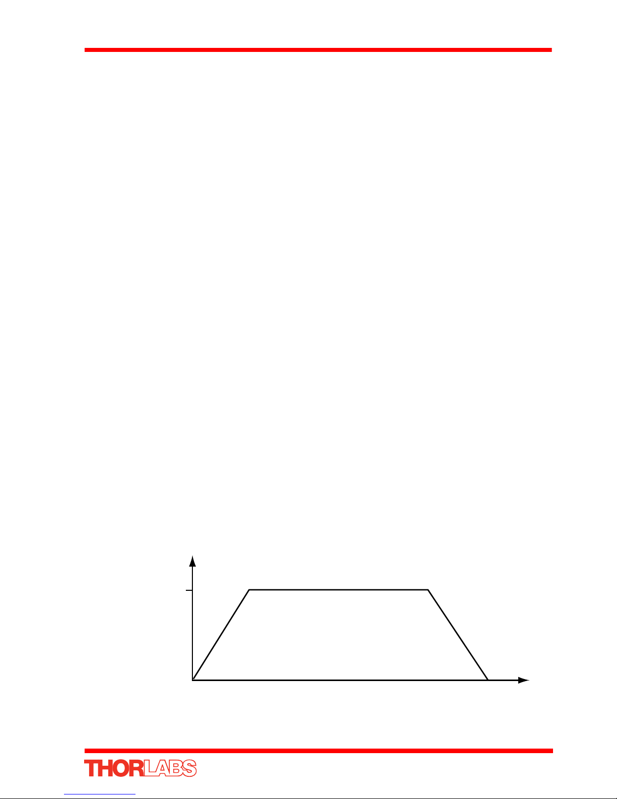
K-Cube Stepper Motor Controller
velocity
maximum
velocity (v)
time
acceleration (slope) a
E.1.2 Positive and Negative Moves
Positive and negative are used to describe the direction of a move. A positi ve move
means a move from a smaller absolute position to a larger one, a negative move
means the opposite.
In the case of a linear actuator, a positive move takes the platform of the stage further
away from the motor.
In a rotational stage, a positive move turns the platform clockwise when viewed from
above.
E.1.3 Velocity Profiles
To prevent the motor from stalling, i t must be ramped up gradually to its maximum
velocity. Certain limits to velocity and acceleration result from the torque and speed
limits of the motor, and the inertia and friction of the parts it drives.
The system incorporates a trajectory generator, which performs calculations to
determine the instantaneous position, velocity and acceleration of each axis at any
given moment. During a motion profile, these values will change continuously. Once
the move is complete, these parameters will then remain unchanged until th e next
move begins.
The specific move profile created by the system depends on several factors, such as
the profile mode and profile parameters presently selected, and other conditions such
as whether a motion stop has been requested. The profile mode can be set to
‘Trapezoidal’ or ‘Bow Index’ as described in Section 6.3.1.
The Trapezoidal profile is a standard, symmetrical acceleratio n/deceleration motion
curve, in which the start velocity is always zero. This profile is selected when the Bow
Index field is set to ‘0’.
In a typical trapezoidal velocity profile, (see Fig. E.2.), the stage is ramped at
acceleration ‘a’ to a maximum velocity ‘v’. As the destination is approached, the stage
is decelerated at ‘a’ so that the final position is approached slowly in a controlled
manner.
Fig. E.2 Graph of a trapezoidal velocity profile
73

Appendix E
BI BI
A
D
-BI -BI
V
Time
Velocity
12 3 4 56 7
A - acceleration
D - deceleration
V - velocity
BI - bow index
The S-curve profile is a trapezoidal curve with an additional ' Bow Value' parameter,
which limits the rate of change of acceleration and smooths out the contours of the
3
motion profile. The Bow Value is specified in mm/s
and is derived from the Bow Index
field as follows:
The Bow Value is applied in mm/s3 and is derived from the Bow Index field as follows:
Bow Value = 2
(Bow Index -1)
within the range 1 to 262144 (Bow Index 1 to 18).
In this profile mode, the acceleration increases gradually from 0 to the specified
acceleration value, then decreases at the same rate until it reaches 0 again at the
specified velocity. The same sequence in reverse brings the axis to a stop at the
programmed destination position.
Example
Fig. E.3 Typical S-Curve Profile
The figure above shows a typical S-curve profil e. In segment (1), the S-curve profile
drives the axis at the specified Bow Index (BI) until the maximum acceleration (A) i s
reached. The axis continues to accelerate linearly (Bow Index = 0) through segme nt
(2). The profile then applies the negative value of Bow Index to reduce the
acceleration to 0 during segment (3). The axis is now at the maximum velocity (V), at
which it continues through segment (4). The profile then decelerates in a similar
manner to the acceleration phase, using the Bow Index to reach the maximum
deceleration (D) and then bring the axis to a stop at the destination.
Note
The higher the Bow Index, then the shorter the BI phases of the curve, and
the steeper the acceleration and deceleration phases. High values of Bow
Index may cause a move to overshoot.
74 HA0362T Rev C Jan 2017

K-Cube Stepper Motor Controller
E.2 Positioning a Stage
E.2.1 General
Whenever a command is received to move a stage, the movement is specified in
motion units, (e.g. millimetres). This motion unit value is converted to microsteps
before it is sent to the stage by the APT software.
Each motor in the system has an associated electronic counter in the controller, which
keeps a record of the net number of microste ps moved. If a request is received to
report the position, the value of this counter is converted back into motion units.
E.2.2 Home position
When the system is powered up, the position cou nters in the controller are all set to
zero and consequently, the system has no way of knowing the position of the stage
in relation to any physical datum.
A datum can be established by sending al l the motors to their ‘Ho me’ positions. The
‘Home’ position is set during manufacture and is determined by driving the motor until
the negative limit switch is reached and then driving positi vely a fixed distance (ze ro
offset). When at the Home position, the counters are reset to zero thereby
establishing a fixed datum that can be found even after the system has been switched
off.
See Section 5.3. for details on performing a Home move.
E.2.3 Limit Switches
A linear stage moves between two stops, and movement outside these limits is
physically impossible. Linear stages can include stages that control the ang le of a
platform within a certain range, although the movement of the platfo rm is not really
linear but angular. Rotary stages can rotate indefinitely, like a wheel.
Linear and rotary stages can contain microswitches that detect certain positions of the
stage, but they differ in the way these switches are used.
All linear stages have a –ve limit switch, to prevent the stage from accidentally being
moved too far in the –ve direction. Once this switch is activated, movement stops. The
switch also provides a physical datum used to find the Home position. Some linear
stages and actuators also have a +ve limit switch (such as the ZST range of
actuators), whereas others rely on a physical stop to halt the motion in the posi tive
direction. A rotary stage has only one switch, used to provide a datum so that the
75

Appendix E
Rotary stageLinear stage
Datum switch
-ve limit switch
+ve limit switch
(or stop)
Travel
Min. position (zero)
(home)
Max. position
Offset
-ve limit switch
SW positive limitSW negative limit
Home position can be found. Movement is allowed right through the switch position in
either direction.
Fig. E.4 Stage limit switches
E.2.4 Minimum and Maximum Positions
These positions are dependent upon the stage or actuator to which the mo tors are
fitted, and are defined as the minimum and maximum useful position s of the stage
relative to the ‘Home’ position - see Fig. E.5.
The distance from the Minimum position to the Maximum position is the ‘useful travel’
of the stage. It is often the case that the Minimum position is zero. The Home and
Minimum positions then coincide, with movement always occurri ng on the positive
side of the Home position.
Rotary stages have effectively no limits of travel. The Minimum and Maximum
positions are conventionally set to 0 and 360 degrees respectively. When the position
of a rotary stage is requested, the answer will be reported as a number between 0 and
360 degrees, measured in the positive direction from the Home position.
Fig. E.5 Minimum and Maximum Positions
76 HA0362T Rev C Jan 2017

K-Cube Stepper Motor Controller
negati ve move
p osi tive mo ve
10mm 20mm
position
E.2.5 Power Saving
The current needed to hold a motor in a fixed position is much smaller than the current
needed to move it. When a stepper motor is at rest it is advisable to reduce the phase
(holding) currents so that the motor does not overheat. Furthermore, this heating can
cause thermal movements through expansion of the metal of the stage.
For this reason, power saving is implemented by default from the software drivers.
When a motor is moving, the ‘Move Power’ is applied. When a motor is stationary, the
‘Rest Power’ is applied. See ‘Phase Powers’ in Section 6.3.3. Stage/Axis Tab for
more details on these power settings.
E.3 Error Correction
E.3.1 Backlash correction
The term backlash refers to the tendency of the stage to reach a different position
depending on the direction of approach.
Backlash can be overcome by always making the last portion of a move in the same
direction, conventionally the positive direction. Consider the situation in Fig. E.6, a
positive move, from 10 to 20 mm, is carried out as one simple move, whereas a
negative move, from 20 to 10 mm, first causes the stage to overshoot the target
position and then move positively through a small amount.
The particular stage selection will usually have this type of ‘backlash correction’
enabled as its default mode of operation, but it can be overridden if the overshoot part
of the move is unacceptable for a particular application.
See Chapter 6 Software Reference, Move/Jogs Tab for details on setting the
backlash correction.
Fig. E.6 Backlash correction
77

Appendix F Regulatory
F.1 Declarations Of Conformity
F.1.1 For Customers in Europe
See Section F.3.
F.1.2 For Customers In The USA
This equipment has been tested and found to comply with the limi ts for a Class A
digital device, persuant to part 15 of the FCC rules. These limits are designed to
provide reasonable protection against harmful interference when the equipment is
operated in a commercial environment. This equipment generates, uses and can
radiate radio frequency energy and, if not installed and used in accordance with the
instruction manual, may cause harmful interference to radio communications.
Operation of this equipment in a residential area is likely to cause harmful interference
in which case the user will be required to correct the interference at his own expense.
Changes or modifications not expressly approved by the company could void the
user’s authority to operate the equipment.
F.2
Waste Electrical and Electronic Equipment
F.2.1 Compliance
As required by the Waste Electrical and Electronic Equipment (WEEE) Directive of
the European Community and the corresponding national laws, we offer all end users
in the EC the possibility to return "end of life" units without incurring disposal charges.
This offer is valid for electrical and electronic equipment
• sold after August 13th 2005
• marked correspondingly with the crossed out "wheelie bin" logo (see Fig. 1)
• sold to a company or institute within the EC
• currently owned by a company or institute within the EC
• still complete, not disassembled and not contaminated
(WEEE)
Directive
78

K-Cube Stepper Motor Controller
Fig. F.1 Crossed out "wheelie bin" symbol
As the WEEE directive applies to self contain ed ope rational electri cal and electronic
products, this "end of life" take back service does not refer to other products, such as
• pure OEM products, that means assemblies to be built into a unit by the user (e. g.
OEM laser driver cards)
• components
• mechanics and optics
• left over parts of uni ts disassembled by the user (PCB's, housings etc.).
If you wish to return a unit for waste recovery, please contact Thorlabs or your nearest
dealer for further information.
F.2.2 Waste treatment on your own responsibility
If you do not return an "end of life" unit to the company, you must hand it to a company
specialized in waste recovery. Do not dispose of the u nit in a litter bin or at a public
waste disposal site.
F.2.3 Ecological background
It is well known that WEEE pollutes the environment by releasing toxic products
during decomposition. The aim of the European RoHS directive is to reduce the
content of toxic substances in electronic products in the future.
The intent of the WEEE directive is to enforce the recycling of WEEE. A controlled
recycling of end of life products will thereby avoid negative impacts on the
environment.
79

Appendix F
F.3 CE Certificate
80 HA0362T Rev C Jan 2017

K-Cube Stepper Motor Controller
Appendix G Thorlabs Worldwide Contacts
USA, Canada, and South America
Thorlabs, Inc.
56 Sparta Ave
Newton, NJ 07860
USA
Tel: 973-579-7227
Fax: 973-300-3600
www.thorlabs.com
www.thorlabs.us (West Coast)
email: feedback@thorlabs.com
Support: techsupport@thorlabs.com
Europe
Thorlabs GmbH
Hans-Böckler-Str. 6
85221 Dachau
Germany
Tel: +49-(0)8131-5956-0
Fax: +49-(0)8131-5956-99
www.thorlabs.de
email: Europe@thorlabs.com
UK and Ireland
Thorlabs Ltd.
1 Saint Thomas Place, Ely
Cambridgeshire CB7 4EX
Great Britain
Tel: +44 (0)1353-654440
Fax: +44 (0)1353-654444
www.thorlabs.de
email: sales.uk@thorlabs.com
Support: techsupport.uk@thorlabs.com
France
Thorlabs SAS
109, rue des Côtes
78600 Maisons-Laffitte
France
Tel: +33 (0) 970 444 844
Fax: +33 (0) 811 381 748
www.thorlabs.de
email: sales.fr@thorlabs.com
Scandinavia
Thorlabs Sweden AB
Bergfotsgatan 7
431 35 Mölndal
Sweden
Tel: +46-31-733-30-00
Fax: +46-31-703-40-45
www.thorlabs.de
email: scandinavia@thorlabs.com
Japan
Thorlabs Japan Inc.
Higashi Ikebukuro
Q Building 1st Floor 2-23-2
Toshima-ku, Tokyo 170-0013
Japan
Tel: +81-3-5979-8889
Fax: +81-3-5979-7285
www.thorlabs.jp
email: sales@thorlabs.jp
China
Thorlabs China
Oasis Middlering Centre
3 Building 712 Room
915 Zhen Bei Road
Shanghai
China
Tel: +86 (0)21-32513486
Fax: +86 (0)21-32513480
www.thorlabs.com
email: chinasales@thorlabs.com
Brazil
Thorlabs Vendas de Fotônicos Ltda.
Rua Riachuelo, 171
São Carlos, SP 13560-110
Brazil
Tel: +55-16-3413 7062
Fax: +55-16-3413 7064
www.thorlabs.com
Email: brasil@thorlabs.com
81

82
Thorlabs Inc.
56 Sparta Ave
Newton, NJ07860
USA
Tel: +1 973 579 7227
Fax: +1 973 300 3600
www.thorlabs.com
Thorlabs Ltd.
Saint Thomas Place, Ely
Cambridgeshire CB7 4EX,
UK
Tel: +44 (0) 1353 654440
Fax: +44 (0) 1353 654444
www.thorlabs.com
 Loading...