


OEM Laser Diode Controller
ITC1xx
Operation Manual
2018

Version:
Date:
3.1
10-Jul-2018
Item No.:
M0009-510-501
Copyright © 2018 Thorlabs GmbH

Contents
Foreword
3
1 General Information 4
2 Getting Started 6
3 Connecting Elements 9
123.2 ST2 I/O D-SUB Connector 15 pin
133.3 ST3 Display Module Connector
133.4 ST4 and ST5 SMB Coaxial Connectors
4 Operating Instruction 14
144.1 Connecting the Power Supply
154.2 Connecting Laser Diode and Photo Diode
41.1 Safety
51.2 Ordering Codes and Accessories
62.1 Parts List
62.2 Operating Principle
72.3 Operating Elements
93.1 ST1 I/O Connector 64 pin
184.3 Connecting TEC and Temperature Sensor
194.4 Connecting the Interlock
204.5 Polarity Check of the TEC
214.6 Operation
224.7 PID Adjustment
5 Connecting Scheme Examples 23
245.1 Laser Diode Controller
265.2 Temperature Controller
6 Display Module ITC100D 28
286.1 Preparing the ITC100D
296.2 ITC100D Jumper Settings
306.3 ITC100D Adjustment
7 Maintenance and Service 31
317.1 Troubleshooting
8 Appendix 33
338.1 Technical Data
338.1.1 Laser Diode Controller
348.1.2 Temperature Controller
358.1.3 Common Specifications
368.2 Dimensions ITC1xx
378.3 Dimensions ITC100D

388.4 Dimensions ITC100F
398.5 Certifications and Compliances
408.6 Warranty
418.7 Copyright and Exclusion of Reliability
418.8 Thorlabs 'End of Life' Policy
428.9 List of Acronyms
438.10Thorlabs Worldwide Contacts

We aim to develop and produce the best solution for your application
in the field of optical measurement technique. To help us to live up to
your expectations and improve our products permanently we need
your ideas and suggestions. Therefore, please let us know about
possible criticism or ideas. We and our international partners are
looking forward to hearing from you.
Thorlabs GmbH
Warning
Sections marked by this symbol explain dangers that might result in
personal injury or death. Always read the associated information
carefully, before performing the indicated procedure.
Attention
Paragraphs preceeded by this symbol explain hazards that could
damage the instrument and the connected equipment or may cause
loss of data.
Note
This manual also contains "NOTES" and "HINTS" written in this form.
Please read these advices carefully!
© 2018 Thorlabs GmbH
3

ITC1xx
1 General Information
The Thorlabs ITC1xx OEM Laser Controller is a compact combined laser current and temperature controller for OEM applications on a single Euro-board (100 x 160 mm).
·
Combined Current and TEC Controllers
·
Maximum laser currents of 200 mA, 1 A, or 3 A
·
Constant Current (CC) and Constant Power (CP) Modes
·
Full PID feedback loop with independent P, I, and D Settings
·
Extensive protection against laser diode damage (softstart, interlock, temperature window
for the laser diode, hardware limitation of TEC and laser current, interlock)
·
Overtemperature protection of the ITC1xx
·
Supports Many Standard Pin Configurations for Easy Integration into Systems
1.1 Safety
Attention
All statements regarding safety of operation and technical data in this instruction manual
will only apply when the unit is operated correctly as it was designed for.
The used with the ITC1xx mai ns power supply must provide a galvanical isolation
between AC mains input and DC output in order to avoid electric shock resulting in damage to your health or even death!
The used pow er supply as well as the ITC1xx m us t be connected properly to the protective earth ground.
The ITC1xx must not be operated in explosion endangered environments!
Refer servicing to qualified personnel!
Only with written consent from Thorlabs GmbH may changes to single components be
made or components not supplied by Thorlabs GmbH be used.
This precision device is only s erviceable if properly packed into the complete original
packaging. If necessary, ask for a replacement package prior to return.
Warning
Laser emission is dangerous to human eye. Do not stare into the emitting aperture, wear
protective glasses and observe the safety instructions supplied with the lase r diode.
Attention
The following statement applies to the products covered in this manual, unless otherwise spe c i fie d herein. The statement for other products will a ppear in the accompanying
documentation.
This equipment has bee n tested and found to comply with the limits for a Class A digital
device, pursuant to pa r t 15 of the FCC Rules and meets a ll requirements of the Canadian
Interference-Causing Equipment Standard ICES-003 for digital apparatus. These limits
are designed to provide reasonable protection against harmful interference w hen the
equipment is opera ted in a commercia l environment. This equipment generates, uses,
and can radia te radio frequency energy and, if not ins tal l e d and us e d in accordance with
the instruction manual, may cause harmful i nter fe r ence to radio communications . Operation of this equipment in a r esidential area is likely to cause harmful interfere nce in
which case the user will be required to correc t the interference at his own ex pense.
Thorlabs GmbH is not responsible for any radi o television interference caus ed by modifications of this equipment or the substitution or attachment of connec ting cables and
© 2018 Thorlabs GmbH4

1 General Information
ITC102
OEM Laser Diode and Temperature Controller, ±200 mA / 12 W
ITC110
OEM Laser Diode and Temperature Controller, ±1 A / 12 W
ITC133
OEM Laser Diode and Temperature Controller, ±3 A / 18 W
ITC100D
Control and Display Panel for the ITC100 Series; removable
ITC100F
Front Plate for ITC100D
ITC100P
Female 64pin DIN Connector
CAB430
Cable for a LD and TEC Controller with 15-Pin D-Sub Connector to a Laser Diode Mount, 1.5 m
equipment other than those spec ified by Thorlabs GmbH. The correction of interference
caused by suc h unauthorized modification, substitution or a ttachment w ill be the re sponsibility of the user.
The use of shielded I/O cables is required when connecting this equipment to any and all
optional peripheral or host devices. Failure to do so may violate FCC and ICES rules.
Attention
Mobile tele phones, ce ll ular phones or other radio transmitters are not to be used within
the ra nge of three meters of this unit si nce the electromagnetic field intensity may then
exceed the maximum allowed disturbance values according to IEC 61326-1.
This product has been tested and found to comply with the limits ac cording to
IEC 61326-1 for using connection cables shorter than 3 meters (9.8 feet).
1.2 Ordering Codes and Accessories
© 2018 Thorlabs GmbH
5

ITC1xx
2 Getting Started
2.1 Parts List
Inspect the shipping container for damage.
If the sh ipping container seems to be d am aged , keep it unt il you have inspected the co nte nts
and you have inspected the ITC1xx mechanically and electrically.
Verify that you have received the following items within the package:
1. ITC102/110/133 OEM Laser Diode and Temperature Controller
2. Operating Manual
2.2 Operating Principle
The I T C1 xx is an 100 x 16 0 mm board level cont roller that combines a low-noise, low-drift current source with a precise TE C controller. De signed for easy integration into OEM applicat ion s,
these euro-sized boards are ideal for products or systems where excellent laser emission stability is required. The analog interfaces offer easy access to parameter settings and readout.
These laser diode con trollers support co nstan t current (CC) and constan t power (CP) modes,
as well as all lase r and monitor diode polarities (CG/AG). The connected laser interface s with
the controller through a 15-pin D-Sub conn ector. A fixed-ground-level d esign significan tly improves noise, tran sient suppression, and output sta bility. T he laser operating current can be
modulated by an external control signal.
The b u ilt-in temperature controller includes a full PID feedback loop with independent P, I, and
D settings, which can be individually optimized. A wide variety of temperature sensors (such as
thermistors and the AD590 temperature transducer) are supported. A standard 64-pin PCB
connector provides access to output signals, analog cont rol inp uts, p ower supply connections,
temperature sensors and thermoelectric cooler elements.
A variety of safety measures allows an easy and safe operation of semiconductor laser diodes.
·
Softstart
·
Interlock
·
Hardware laser current limit
·
Hardware TEC current limit
·
Over temperature protection
·
Temperature window for the laser diode
·
Power supervision
Other features:
·
Constant current or constant power mode
·
Bipolar operation of laser diodes
·
2 mA floating photo current input
·
Modulation input
·
Individual TEC controller PID adjustment possible
·
Thermistor or AD590/LM335 temperature sensor selectable
·
Temperature tune input
·
Analog control output for ILD, ILIM, IPD, TSET, TACT, ITLIM, ITEC
© 2018 Thorlabs GmbH6

2.3 Operating Elements
2 Getting Started
© 2018 Thorlabs GmbH
7

ITC1xx
P1
Sets the laser diode limit current
P2
Adjusts the laser set current or power (depending on CC or CP Mode)
P3
Sets the TEC current limit
P4
Adjust the set temperature (transducer) or resistance (thermistor)
P5
TEC P share
P6
TEC I share
P7
TEC D share
P8
Define the TEC temperature window
P9
For CMR adjustment. Should not be changed by the user.
S1
Laser current controller mode
Switch to the left = constant power mode (CP)
Switch to the right = constant current mode (CC)
S2
Laser diode polarity
Switch to the left = cathode grounded (CG)
Switch to the right = anode grounded (AG)
S3
Temperature sensor selection
Switch to the left = thermistor
Switch to the right = transducer (AD590 etc.)
S4
TEC I share ON/OFF
Switch towards ST2 = TEC I share ON
Switch towards ST1 = TEC I share OFF.
JP1
Bias+
Jumper closed: bias+ connected to ST2 Pin 12 1)
Jumper open: bias+ disconnected from ST2 Pin 12 1)
JP2
Bias-
Jumper closed: bias- connected to ST2 Pin 9
1)
Jumper open: bias- disconnected from ST2 Pin 9
1)
JP4
TEC window
Jumper closed: TEC window OFF
Jumper open: TEC window ON
LED1a
Laser ON (Upper LED)
LED1b
TEC ON (Lower LED, closest to the PCB)
LED2
Power Supply OK
LED3
TEC temperature out of window
Potentiometers
Switches
Jumper
1)
For compatibility with Thorlabs laser diode mounts
LEDs
© 2018 Thorlabs GmbH8

3 Connecting Elements
Numbering of ST1 pins
Short Description of ST1 Pin Assignment
3.1 ST1 I/O Connector 64 pin
3 Connecting Elements
The following table lists the pin assignment of ST1 with respect to their functionality.
© 2018 Thorlabs GmbH
9

ITC1xx
Pin
Function
Range / Coefficient
ITC102
ITC110
ITC133
A30,C30
Supply voltage +11.4 V to +15.8 V
2.4 A 1)
3.2 A 1)
3.2 A 1)
A31,C31
Supply voltage ground
A32,C32
Supply voltage -11.4 V to -15.8 V
2.4 A 1)
3.2 A 1)
3.2 A 1)
A8, C8, A14, A16, A18, A21, C21
Analog measurement ground
Pin
Function
Range / Coefficient
ITC102
ITC110
ITC133
Temperature Controller
A4,C4
TEC - (GND)
±2 A
max. ±6 V
±2 A
max. ±6 V
±3 A
max. ±6 V
A5,C5
TEC +
C6
AD590 +
- 20 to +80 °C / 253.2 to 353.3 µA
1 µA/°C
A6
AD590 -
A7
Thermistor (GND)
100 W to 80 k
W
C7
Thermistor
C9
I
TEC
(Measurement voltage; -5 to +5 V)
2.5 V/A
2.5 V/A
1.667 V/A
A9
I
TEC, LIM
(Measurement voltage; 0 to +5 V)
2.5 V/A
2.5 V/A
1.667 V/A
A10
D
T / D R (Measurement voltage; -5 to +5 V)
0.5 V/°C (transducer)
-0.5 V/W (thermistor)
C10
T
act
/ R
act
2) (Measurement voltage)
-1 to + 4 V / 50 mV/°C (transducer)
+5 mV to +4 V / 50 mV/kW (thermistor)
C11
T
set
/ R
set
(Measurement voltage)
A11
T
tune
(Control voltage; -5 to +5 V)
20 °C/V (transducer)
16 kW/V (thermistor)
Laser Diode Current Controller
A15
LD Modulation Input (-5 to +5 V)
40 mA/V
200 mA/V
600 mA/V
A19
IPD 2) (Measurement voltage; 0 to +5 V)
2.5 V/mA
A20
ILD 2) (Measurement voltage)
0 to +5 V (CG) / 0 to -5 V (AG)
25 V/A
5 V/A
1.667 V/A
C20
I
LD, LIM
(Measurement voltage; 0 to +5 V
25 V/A
5 V/A
1.667 V/A
A22
Output PD Bias -
-5 V const.
C22
Output PD Bias +
+5 V const.
A23
Monitor (Photo) Diode Cathode
0 to 2 mA
(floating; differential input)
C23
Monitor (Photo) Diode Anode
A24,C24
Laser Diode Anode (CG)
+0.2 A
max. 4 V
+1.0 A
max. 4 V
+3.0 A
max. 4 V
A25,C25
Laser Diode GND
A26,C26
Laser Diode Cathode (AG)
-0.2 A
max. 4 V
-1.0 A
max. 4 V
-3.0 A
max. 4 V
Power Supply
Analog Signals
1) Without display module ITC100D
2) If a long connection cable is attached to this output, a 1 kW resistor should be inserted in series as close as possible to the output pin.
© 2018 Thorlabs GmbH10

Digital Signals
Pin
Function
Logical Level
Temperature Controller
A13
TEC ON control input
H = TEC On
A12
TEC ON control output (open collector)
L = TEC on
C12
TEMP ERROR output (open collector)
L = Temperature window exceeded
C13
OTP output (open collector)
L = Heat sink over-temperature
C14
Digital GND (Common pin for all digital signals)
Laser Diode Current Controller
C15
LD ON control input
H = Laser on
A17
TTL MOD input
H = Laser on
C16
LD ON control output (open collector)
L = Laser on
C18
LIMIT LD control output (open collector)
L = Laser current limit reached
C17
Interlock
Interlock = CLOSED when connected
to C17 (R £ 430 W)
3 Connecting Elements
© 2018 Thorlabs GmbH
11

ITC1xx
Pin
Function
Range
ITC102
ITC110
ITC133
Temperature Controller
8
TEC - (GND)
±2 A
max. ±6 V
±2 A
max. ±6 V
±3 A
max. ±6 V
7
TEC +
6
AD590 +
- 20 to +80 °C / 253.2 to 353.3 µA
13
AD590 -
14
Thermistor (GND)
100 W to 80 k
W
15
Thermistor
Laser Diode Current Controller
11
Laser Diode Anode (CG)
+0.2 A
max. 4 V
+1.0 A
max. 4 V
+3.0 A
max. 4 V
3
Laser Diode GND
10
Laser Diode Cathode (AG)
-0.2 A
max. 4 V
-1.0 A
max. 4 V
-3.0 A
max. 4 V
2
Monitor (Photo) Diode Cathode
0 to 2 mA
(floating; differential input)
4
Monitor (Photo) Diode Anode
9
Output PD Bias - (set with JP2)
-5 V const.
12
Output PD Bias + (set with JP1)
+5 V const.
1
Interlock
Interlock = CLOSED when connected
to pin 5 (R £ 430 W)
5
Interlock GND
3.2 ST2 I/O D-SUB Connector 15 pin
The following table lists the pin assignment of ST2 with respect to their functionality.
© 2018 Thorlabs GmbH12

3.3 ST3 Display Module Connector
Pin
Function
1
-9 V (not in use)
2
0 V Power supply for ITC100D
3
+5 V Power supply for ITC100D
4
Output IPD_DISP
5
Output ILD_DISP
6
Output ILDLim_DISP
7
Output TSET_DISP
8
Output TACT_DISP
9
Output ITECLim_DISP
10
Common ground for pin 4 to pin 9
Function
Coefficient
ITC102
ITC110
ITC133
ST4
Laser Diode Modulation Input LD MOD
(-5 V to +5 V)
40 mA/V
200 mA/V
600 mA/V
ST5
Temperature Tune Input T TUNE
(-5 V to +5 V)
20 °C/V (transducer)
16 kW/V (thermistor)
3.4 ST4 and ST5 SMB Coaxial Connectors
3 Connecting Elements
© 2018 Thorlabs GmbH
13

ITC1xx
4 Operating Instruction
4.1 Connecting the Power Supply
The ITC1xx OEM board requires a supply voltage of ± (1 2 ... 15) V for internal operation and for
power supply of the laser diode and the TEC element.
The power supply must be regulated and free of ripple. The voltage must not e xceed the range
of ± (11.4 ...15.8) V. L ower voltages will ca use the unit to o perat e improperly, higher voltages
may damage the ITC1xx.
The power supply must be able to deliver the following curren t, both for the positive a n d negative supply voltage:
ITC102: 2.4 A
ITC110: 3.2 A
ITC133: 3.2 A
Note
Above current values are given without respect to po wer co nsu mp tion of the ITC100D display
module, if used.
Note
The total combined o u t p ut current for the I TC133 is limited by the total therma l dissipation loss.
With the standard heat sink, the t otal output current should be limited to 3 A (ILD+I
TEC
optimized cooling, e.g. using a fan o r a bigger h eat sink, allows 3 A LD current and 3 A TE C
current at the same time, provided that the power supply can deliver 6.1 A.
Note
With ±15 V power supply and high o utput currents, the internal power dissipation o f the ITC1xx
increases significantly. This may cause a degradation of the specifications. In such cases the
use of a ±12 V supply is recommended.
The in crease of the heat sink te m p era tu re for a vertically installed ITC1xx bo a rd without forced
air cooling can be calculated as follows:
(US = Supply voltage)
Example:
I
TEC,out
= 2 A; U
TEC,out
= 2.5 V; I
LDCOUT
= 0.2 A; U
LDCOUT
= 2V; US = ±12V
This results in an temp erature increase ∆T = 37.6 K. At 25 °C ambient temperatu re the heat
sink temperature reaches 62.6 °C.
Note
Using the ITC1xx with the display module ITC100D leads to an add ition al increa se of the heat
sink temperature for about 3 K.
The horizontal m ou nting of the ITC1xx board degrades the heat dissipation , so that the hea t
sink temperature increases! Forced air cooling may be required.
The maximum heat sink temperature is +85° C. When this lim it is exceed e d , the over-temperature protect ion activates and switches of f the TEC and LDC outputs. The controller ca n be
switched on again only after the temperature has dropped by about 10° C.
© 2018 Thorlabs GmbH14

4 Operating Instruction
4.2 Connecting Laser Diode and Photo Diode
The ITC1xx OEM controllers are designed to drive laser diodes up to a maximum current of
0.2 A, 1 A or 3 A, depending on the type, either with laser diode anode or cathode grounded.
The lase r diode is always sourced with respect to ground. Compared to a floating driver stage,
this operation mode is a dvanta geous with respe ct to laser diode protection and to the st ab ility
of the laser current.
The pho to d io d e can b e used either f lo a tin g, or with anode o r cathode grounded. Additionally, a
bias voltage can be applied.
Connect the laser diode and the photodiode using shielded, twisted pair cables. T he anode and
cathode connection of each device should be twisted.
Warning
Disconnecting the laser diode during operation may destroy the laser diode!
Below are shown possible configurations of th e laser an d m onitor (ph oto) diode combination
and the connection scheme to the output connectors ST2 or ST1.
AG = Anode Grounded
CG = Cathode Grounded
© 2018 Thorlabs GmbH
15

ITC1xx
Laser diode AG, photo diode CG, no bias:
Laser diode AG, photo diode AG, no bias:
Laser diode AG, photo diode floating, no bias:
The connection, sh own as dashed line, can b e made either at the laser or at the ITC1xx connector.
Laser diode AG, photo diode CG, -5 V bias:
Laser diode AG, photo diode AG, +5 V bias:
Attention
Reverse connection of the photo diode can pe rmanently damage the photo diode when using a
bias voltage. Check the control voltage o utpu t IPD (A19) prior to enabling a bias voltage. The
output voltage must be positive!
© 2018 Thorlabs GmbH16

Laser diode CG, photo diode CG, no bias:
Laser diode CG, photo diode AG, no bias:
Laser diode CG, photo diode floating, no bias:
4 Operating Instruction
The connection, sh own as dashed line, can b e made either at the laser or at the ITC1xx connector.
Laser diode CG, photo diode CG, -5 V bias:
Laser diode CG, photo diode AG, +5 V bias:
Attention
Reverse connection of the photo diode can pe rmanently damage the photo diode when using a
bias voltage. Check the control voltage o utpu t IPD (A19) prior to enabling a bias voltage. The
output voltage must be positive!
© 2018 Thorlabs GmbH
17

ITC1xx
4.3 Connecting TEC and Temperature Sensor
In the drawings below, the bold pin numbers correspond to the n umb ering of the 15 pin D-
Sub connector ST 2 , while p in numbers in (parantesis) co rrespon d to the pin nu m bering of the
64 pin connector ST1.
Connecting the TEC Element
Attention
Make sure that th e p olarity of th e T E C elem en t (Peltie r) is correct! Otherwise, the tem pe ratu re
will run into the wrong direction, this way leading to a thermal damage of the laser diode!
Connecting a thermistor (NTC temperature sensor)
Connecting an AD590 temperature sensor
Connecting a LM335 temperature sensor
© 2018 Thorlabs GmbH18

4 Operating Instruction
4.4 Connecting the Interlock
The interlock represents a current source (output pin 1 of ST2 resp. C17 of ST1), with the return pin 5 (ST2) o r C14 (ST1). The voltage between pin 1 and 5 (or C14 an d C17) is observed
and used for enabling / disabling the output of the laser current controller.
Below are shown possible external connections to the interlock:
The voltage across the interlock pins m ust not exceed ~ 2.5 V, ot herwise the interlock is considered as open. For this reason, the resistance of the external interlock circuit m ust be
between 0 and 430 W.
It is also possible to connect an LED (current through the LED is about 3.5 mA) as shown in the
right diagram . In this case the LED serves as an additional signal that the laser current is
switched on.
When t he la ser cu rrent is switched on, the interlock is ch ecke d - if it is open, the lase r cannot
be switched on. If th e inte rlock is interrupt ed during laser ope ration , th e lase r is shut down immediately, so the interlock circuit can be used fo r e m ergency switch-off of the la ser current as
well.
When using the ITC1xx with Th orlab s laser diode mounts, the interlock f u nctio n is provided b y
the mount. For details please see the Operation Man ual of the used laser diode mount.
© 2018 Thorlabs GmbH
19

ITC1xx
4.5 Polarity Check of the TEC
Preconditions
·
Connect TEC element and temperature sensor (see section Temperature Controller). The
sensor must have good thermal contact to the active surface of the TEC element.
·
Switch on the ITC1xx.
·
Select the correct type of sensor (switch S3).
·
Set the appropriate value1) for I
TEC,LIM
ST1).
Polarity check of the TEC element
·
Adjust the temperature set point T
C11 of ST1) a few degrees away from the actual room temperature.
·
Observe T
·
If T
ACT
or R
or R
ACT
runs away from the set point, the TEC element is reverse poled . Change
ACT
(ST1 pin C10) and switch on the module.
ACT
polarity and repeat the procedure.
, using the potentiometer P3 (measured at pin A9 of
SET
or R
using the potentiometer P4 (measured at pin
SET
·
If T
ACT
or R
is oscillating around the set point, the TEC element is con nected correctly,
ACT
but the P-, I- and D share values of the control loop need to be adjusted.
·
If T
ACT
or R
is settling properly to the set point, the TEC element has been connected
ACT
correctly, however the values for the P-, I- and D share of the control loop might still need
to be adjusted (Refer to section PID Adjustment).
1
) The total com bined current f or the IT C133 is limited by the total th ermal dissipation loss.
When the standard heat sink is used, the total o utput current should be limited to 3 A (ILD + I
£
3 A). Op timized cooling by fan or bigger heat sink allows 3 A LD and 3 A T EC at the same
time under the condition that the power supply provides 6.1 A.
TEC
© 2018 Thorlabs GmbH20

4 Operating Instruction
4.6 Operation
Switch the ITC1xx module On/Off
The laser current and the temperature controller are switched on and of by logic signals. These
signals are applied to the 64 pin connect or ST1:
·
pin C15: Laser current controller - H = On; L = Off
·
pin A13: Temperature controller - H = On; L = Off
Voltage levels:
·
+2.0 V £ H £ +25.0 V
·L £
Either TTL or CMOS signals can be applied, as well as the positive supply voltage can be used.
The input resistance is about 10 k
Note
Please remember tha t the interlock circuit must b e closed to enable th e switch-on o f the laser
current.
+1.1 V
W.
Setting a Temperature Window
A temperature window can be enabled in order to protect the laser diode.
·
The temperature controller must not be switched on!
·
Keep your temperature sensor on a constant temperature.
·
Adjust the temperature set point T
SET
or R
using the potentiometer P4 (measured at pin
SET
C11 of ST1) in such a way that the difference between actual and set temperature corres-
ponds to the desired temperature window.
·
Now remove jumper JP4 and set potentiometer P8 fully clockwise (window = infinite).
·
Rotate P8 slowly counter clockwise until LED3 lights up.
·
The ITC1xx now is running in temperature protection mode.
© 2018 Thorlabs GmbH
21

ITC1xx
4.7 PID Adjustment
A temperature control loop works compa rab ly slow. Regulation oscillations h a ve a p e riod in t h e
range of seconds.
The PID adjustmen t will opt imize th e dynamic behavior. The IT C1xx temp eratu re controller allows the three control loop parameters P, I and D to be set independently from 5% to 100%.
Example of a PID adjustment
Pre-condition:
All limit values are set correctly, all polarities are correct, all set and relevant calibration values
are entered, ambient temperature is about 20 °C.
·
Switch off the I share (switch S4 to OFF).
·
Set the P, I and D share to minimum (turn P5, P6 and P7 fully counter clockwise).
·
Observe the actual temperature T
C10) and switch on the temperature controller.
P share
·
Change the set temperature repeatedly between about 18 °C and 22 °C while observing
the settling behavior of the actual temperature.
·
Increase the P share gradually. Higher values will increase the sett ling speed, too high
values lead to regulation oscillations.
·
The P share has been set correctly if after only 2-3 overshoots t he actual temperature remains stable close to the set temperature.
or the actual thermistor resistance R
ACT
(ST1 pin
ACT
D share
·
Change the set temperature repeatedly between about 18 °C and 22 °C while observing
the settling behavior of the actual temperature.
·
Increase the D share gradually. Higher values will decrease the amplitude of the overshoots.
·
The D share is set correctly when the actual temperature remains stable close to the set
temperature after a minimum of overshoots.
I share
·
Turn on the I share (switch S4 to ON).
·
Change the set temperature repeatedly between about 18 °C and 22 °C while observing
the settling behavior of the actual temperature.
·
Increase the I share gradually. Higher values will accelerate the settling to the set temperature.
·
The I share is set correctly when the actual temperature reaches the set temperature in
shortest time without overshoots.
Note
In case of a high thermal load, the adjustment ranges of the I and D shares might be insufficient. The adjustment range can be increased by using additional foil capacito rs: C73 for the D
share and C75,C76 and C77 for the I share, typically 0.47 µF t o 3.3 µF.
© 2018 Thorlabs GmbH22

5 Connecting Scheme Examples
5 Connecting Scheme Examples
Below are given some examples of how to connect the ITC1xx.
The 64 p in conne cto r ST1 allows to establish all necessary co n ne ctio ns. This is advantageous
when using the ITC1xx in OEM applications.
Alternatively, the laser, the m onito r diode, the temperature sensor, the TEC and the interlock
connection can be made throu gh the 15 pin DSUB con ne ctor ST2. This way, a Th orlab s laser
diode mount can be connected directly using the CAB430 cable (to be ordered separately).
Below are given some schematic examples how to connect peripherals to the ITC1xx for the
case of using ST1 only, and for the case using both the ST1 and ST2 connectors.
For cle arne ss reason s, the con ne ction s of the the laser current controller and the temperature
controller are separated.
© 2018 Thorlabs GmbH
23

ITC1xx
5.1 Laser Diode Controller
In the above schematic diagram a laser diode (AG - anode grounded) and a monitor (photo) diode (CG - cathode grounded) are connected to the 64 pin ST1.
© 2018 Thorlabs GmbH24

5 Connecting Scheme Examples
In the above schematic diagram a laser diode (AG - anode grounded) and a monitor (photo) diode (CG - cathode grounded) are connected to the 15 pin DSUB connector ST2.
© 2018 Thorlabs GmbH
25

ITC1xx
5.2 Temperature Controller
In the above schema tic diagram a TEC eleme nt (Peltier) and a thermistor temperature sensor
are connected to the 64 pin ST1.
© 2018 Thorlabs GmbH26

5 Connecting Scheme Examples
In the above sche matic dia gram the TEC element (Peltier) and the thermistor temperature
sensor are connected to the 15 pin DSUB connector ST2.
© 2018 Thorlabs GmbH
27

ITC1xx
P1 P2 P3 P4 P5 P6
6 Display Module ITC100D
Thorlabs GmbH offers an optional ITC100D disp la y module that can be mounted directly to the
ITC1xx board. The ITC100D module can be covered using the optional ITC100F front panel.
An numeric 3½ digit d isplay with selectable by the user decimal p oint position will display the
selected by the rotary switch parameter. Below the parameters are listed in the order when
turning the rotary switch from the left to the right stop:
·
Monitor (photo) diode current I
·
Laser diode current I
·
Laser diode current limit I
·
Temperature set point T
·
Actual temperature T
·
TEC current limit I
LD
ACT
TEC,LIM
(transducer) or R
PD
LD,LIM
(transducer) or R
SET
(thermistor)
SET
(thermistor)
ACT
6.1 Preparing the ITC100D
The ITC100D can be m ounted d irectly to the ITC1xx board. Fix the displa y module to the
threaded holes in the heat sink using the included two screws and distance holders.
Alternatively, the ITC100D can be mounted separately.
Insert the ribbon cable connector of the ITC100D into ST3 of the ITC1xx board.
© 2018 Thorlabs GmbH28

6 Display Module ITC100D
ITC1xx Type
Position of jumper "ILD"
Position of jumper "I
LIM
"
ITC102
1
1
ITC110
3
3
ITC133
2
2
Parameter
ITC102
ITC110
ITC133
I
PD
mA
mA
mA
I
LD
mAAA
I
LD,LIM
mAAA
T
SET
/ T
ACT
(transducer)
°C°C°C
R
SET
/ R
ACT
(thermistor)
kWkWk
W
I
TEC,LIM
AAA
6.2 ITC100D Jumper Settings
On t he I TC100D PCB are two jumper banks (see red marking) that allow to set the po sition of
the decimal point for the display according to the type of ITC1xx.
Set the jumpers depending on the ITC1xx type as listed below:
This results in the following units for the six selectable parameters:
© 2018 Thorlabs GmbH
29

ITC1xx
6.3 ITC100D Adjustment
The ITC100D is factory adjusted. However, in order to ensure the best display accuracy, it is recommended to re-adjust it from time to time.
The adjustment is carried out a t a single set point, using the ad justm en t potentiometers P1 to
P6:
P1 - Adjust I
PD
Inject a known current from an externa l sou rce in to th e p h o to cu rrent inp u t (pins A 23 an d C23
of ST1). The current should be about 90% of full scale.
Use P1 to adjust the display reading to the input current value.
P2 - Adjust I
LD
Set the la se r controller to constant current mode. A d ju st the laser current limit to maximum current and the laser current setting to about 9 0 % of maximum current. Connect an ampere meter
to the laser output pins.
Use P2 to adjust the ITC100D reading to the measured output current.
P3 - Adjust I
LD,LIM
Set the laser controller t o constant current mode. Adjust the laser current limit to abou t 90% of
maximum cu rrent and the laser current setting to maximum current. Connect an ampere meter
to the laser output pins
Use P3 to adjust the ITC100D reading to the measured output current.
P5 - Adjust T
ACT
Set the temperature sensor t o a well defined temperatu re and adjust t he ITC100D reading to
that temperature using P5.
P4 - Adjust T
SET
Adjust the set temperature to about 90% of the full scale value. Turn on the temperature control
and wait until temperature has settled. Read the actual temperatu re T
bring the reading in accordance with T
using the potentiometer P4.
ACT
, switch to T
ACT
SET
and
Note
T
must be calibrated first!
ACT
P6 - Adjust I
TEC,LIM
Connect an ampere met er to the TEC outp ut pins. Ad ju st the TE C current limit to about 90% of
full scale. Adjust the temperature set point to a significant higher value and turn on temperature
control.
Adjust the I
TEC,LIM
reading to the ampere meter value using P6.
© 2018 Thorlabs GmbH30

7 Maintenance and Service
7 Maintenance and Service
Protect the ITC1xx from adverse weather co nditions. The ITC1xx is not water resistant.
Attention
To avoid damage to the instrument, do not expose it to spray, liquids or solvents!
The unit do es not need a regular maintenance by the user. It does not contain any modu les
and/or components th at could be repaired by th e user himself. If a malfunction o ccurs, please
check first the section Troubleshooting prior to contact Thorlabs GmbH for return instructions.
7.1 Troubleshooting
·
Unit does not work at all (no display)
Ø
Is the controller connected properly to the external power supply?
·
Connect the ITC1xx to a stable DC power supply with an output voltage (±12 to ± 15
V) and make sure, it is switched on.
·
You don’t get the desired laser output power
Ø
Is the interlock closed?
·
Check the resistance between the interlock pins of the connector jack - it must not
exceed 430 W.
Ø
Is the laser output turned on?
·
Apply a logical "high" level to pin C15 of ST1 to turn on the laser output. The LED1a
on the controller board must light up.
Ø
The hardware limit I
·
Adjust the hardware limit I
Ø
Is the laser diode installed properly?
·
Check the connection cables.
Ø
Is the switch S2 set according to the laser diode polarity?
·
Verify correct polarity and set S2 accordingly.
Ø
Is the photo diode connected properly?
·
Check the connecting cable.
Ø
Are you using a bias voltage with the photo diode in photo current mode?
·
Turn off bias voltage by interrupting the wiring bridge or change the polarity of the diode for photo element mode (refer to section Connecting Laser Diode and Photo Di-
ode)
might be set to 0.
LIM
using P1 to the desired value (pin C20 of ST1)
LIM
Ø
Is the desired output power adjusted correctly?
·
Set the ITC1xx to constant power mode (S1) and adjust the desired output power
PLD, using P2.
Ø
Is the ITC1xx running in temperature p rotection mode?
·
Check if the temperature window is set correctly.
·
Check if the laser temperature is out of window (laser is then switched off automatically).
© 2018 Thorlabs GmbH
31

ITC1xx
·
You don’t get the desired laser operation temperature
Ø
Is the TEC connected properly to the connector?
·
Check all connections and cables.
·
Check the correct TEC polarity.
Ø
Is the temperature controller turned on?
·
Apply a logical "high" level to pin A13 of ST1 to turn on the laser output. The LED1b
on the controller board must light up.
Ø
Is the temperature sensor connected properly and is the temperature set accordingly?
·
Check the connection and p olarity of the temperature sensor - p le ase refer to section
Connecting TEC and Temperature Sensor.
·
Adjust P4 to the desired temperature (C11 of ST1).
Ø
The TEC current limit might be set to 0?
·
Adjust P3 to the desired TEC current limit (A9 of ST1).
Ø
Is the ITC1xx set correctly for the used temperature sensor?
·
Select the temperature sensor using S3.
·
Set temperature differs from actual temperature (of the laser)
Ø
Is the temperature oscillating?
·
Adjust the PID parameters carefully - please refer to section PID Adjustment.
If an error or malfunction appears that is not listed above, please contact Thorlabs.
© 2018 Thorlabs GmbH32

8 Appendix
Parameter
ITC102
ITC110
ITC133
Current Control
Display Laser Current on
LED
Trim Potentiometers (15-Turn)
ILD, IPD resp. PLD, I
LD,LIM
Control Range of Laser Current
0 to ± 200 mA
0 to ± 1 A
0 to ± 3 A 1)
Compliance Voltage
> 4 V
Setting Accuracy / Repeatability (full scale)
± 2 % typ. / ± 0.1 %
Noise (10Hz to 10MHz, rms)
< 2 µA
< 6 µA
< 25 µA
Drift (30 min, 0 to 10Hz, typ.)
< 20 µA
< 100 µA
< 300 µA
Temperature Coefficient
< 50 ppm/°C
Power Control
Control Range Photo Diode Current
5 µA to 2 mA
Accuracy / Repeatability (full scale)
± 2% typ. / ±0.1%
Photodiode Reverse Bias Voltage
0 V or 5 V
Current Limit
Setting Range
0 to >200 mA
0 to >1 A
0 to >3 A
Setting Accuracy / Repeatability (full scale)
± 2% typ. / ± 0.1%
Analog Modulation Input
Input Resistance
10 k
W
Modulation coefficient, CC
40 mA/V ±5%
200 mA/V ±5%
600 mA/V ±5%
Small Signal 3 dB-Bandwidth, CC
DC to 200 kHz
DC to 50 kHz
DC to 20 kHz
Modulation Coefficient, CP
0.4 mA/V ±5%
TTL Modulation Input
Rise/Fall Time
< 10 µs
< 50 µs
< 100 µs
TTL Control Input
LD ON
Measurements and Control Outputs
Analog Measurement Values
ILD, IPD, I
LD,LIM
Measurements Outputs
0 to ± 5 V
Measurements Accuracy typ. (Load > 500kW)
± 2%
TTL Control Outputs
LD ON, LIMIT
8.1 Technical Data
8.1.1 Laser Diode Controller
8 Appendix
1
) The total combined current for the ITC133 is limited by the total thermal dissipation loss. Optimized cooling by
fan or bigger heat sink allows 3 A LD and 3 A TEC at the same time provided the power supply provides 6.1 A.
All technical data are valid at 23 ± 5°C and 45 ± 15% rel. humidity (non condensing)
© 2018 Thorlabs GmbH
33

ITC1xx
Parameter
ITC102
ITC110
ITC133
Temperature Control
Display TEC current ON
LED
Trim Potentiometers (15-Turn)
I
TEC,LIM
, T
SET
/ R
SET
Trim Potentiometers (1-Turn)
P, I and D Share
TEC Output
Control Range of TEC Current
-2 A to +2 A
-3 A to +3 A 1)
Compliance Voltage
> 6 V
Maximum Output Power
12 W
18 W
Noise and Ripple
< 1 mA
< 3 mA
Thermistor Temperature Sensors
Control Range
100 W to 80 k
W
Setting Accuracy (full scale, typ.)
± 2%
Repeatability (full scale)
± 0.1%
Temperature Stability typ.
< 2
W
IC Temperature Sensors AD590, AD592, & LM335
Control Range
- 20 °C to +80 °C
Setting Accuracy (full scale, typ.)
± 2%
Repeatability (full scale)
± 0.1%
Temperature Stability typ.
< 0.004 °C
TEC Current Limit
Setting Range
Accuracy typ.
± 5%
Temperature Control Inputs
Analog Control Input
T
SET
/ R
SET
Input Resistance
10 k
W
Input Coefficient Thermistor
16 kW/V
Input Coefficient IC-Sensor
20 °C/V
TTL Control Input
TEC ON
Measurement and Control Outputs
Analog Outputs
T
SET/RSET
, T
ACT/RACT
, I
TEC,LIM
(I
TEC
, DT/DR)
Measurement Accuracy typ. (Load > 500 kW)
±2%
TTL Control Outputs
TEC ON, TEMP OK
8.1.2 Temperature Controller
1
) The total combined current for the ITC133 is limited by the total thermal dissipation loss. Optimized cooling by
fan or bigger heat sink allows 3 A LD and 3 A TEC at the same time provided the power supply provides 6.1 A.
All technical data are valid at 23 ± 5°C and 45 ± 15% rel. humidity (non condensing)
© 2018 Thorlabs GmbH34

8 Appendix
ITC102
ITC110
ITC133
Supply Voltage/Current
±12 V to ±15 V
2.3 A
±12 V to ±15 V
3.1 A
±12 V to ±15 V
3.1 A 1)
Operating Temperature
0 to + 40 °C
Storing Temperature 2)
-40 °C to +70 °C
Warm-Up Time for Rated Accuracy
10 min
Dimensions (W x H x D)
100 x 42 x 160 mm (Eurocard)
Weight
< 0.7 kg
8.1.3 Common Specifications
1
) The total combined current for the ITC133 is limited by the total thermal dissipation loss. Optimized cooling by
fan or bigger heat sink allows 3 A LD and 3 A TEC at the same time provided the power supply provides 6.1 A.
2
) non-condensing
All technical data are valid at 23 ± 5°C and 45 ± 15% rel. humidity (non condensing)
© 2018 Thorlabs GmbH
35

ITC1xx
All dimensions in mm
8.2 Dimensions ITC1xx
© 2018 Thorlabs GmbH36
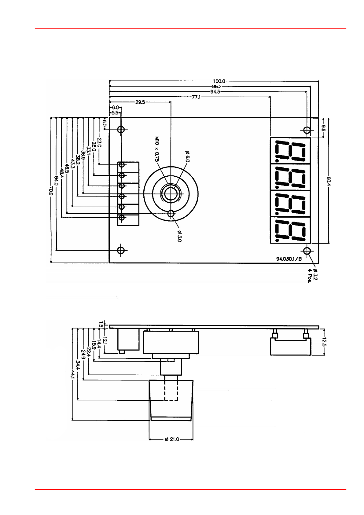
8.3 Dimensions ITC100D
All dimensions in mm
8 Appendix
© 2018 Thorlabs GmbH
37

ITC1xx
All dimensions in mm
8.4 Dimensions ITC100F
© 2018 Thorlabs GmbH38

8.5 Certifications and Compliances
Category
Standards or description
EC Declaration of
Conformity - EMC
Meets intent of Directive 2004/108/EC 1 for Electromagnetic Compatibility. Compliance was
demonstrated to the following specifications as listed in the Official Journal of the European
Communities:
EN 61326-1:2006
Electrical equipment for measurement, control and laboratory use –
EMC requirements:
Immunity: complies with basic immunity test requirements
2,3,5
.
Emission: complies with EN 55011 Class A Limits
2,3,4
IEC 61000-4-2
Electrostatic Discharge Immunity (Performance Criterion B)
IEC 61000-4-3
Radiated RF Electromagnetic Field Immunity (Performance Criterion
B) 6IEC 61000-4-4
Electrical Fast Transient / Burst Immunity (Performance Criterion B)
IEC 61000-4-6
Conducted RF Immunity (Performance Criterion B)
EN 61000-3-2
AC Power Line Harmonic Emissions
Australia / New Zealand Declaration of
Conformity
Complies with the Radiocommu ni c a ti on s Act and demonstrated per EMC Emission standard
2,3,4:
AS/NZS 2064
Industrial, Scientific, and Medical Equipment: 1992
FCC EMC Compliance
Emissions comply with the Class A Limits of FCC Code of Federal Regulations 47, Part 15,
Subpart B
2,3,4
.
1
Replaces 89/336/EEC.
2
Compliance demonstrated us ing high-quality shielded interface cables shorter than or equal to 3 m eters, including CAB400
cable installed at the CONTROL OUT port and with CAB430 cable installed at the LD/TEC port.
3
Compliance demonstrated with ITC100 series and DISP100 board modules installed in a Thorlabs PRO8000 mainframe unit
(with PRO8000 display disabled).
4
Emissions, which exceed the levels required by these standards, may occur when this equipment is connected to a test object.
5
Minimum Immunity Test requirement.
6
MOD IN port capped at IEC 61000-4-3 test.
8 Appendix
© 2018 Thorlabs GmbH
39

ITC1xx
8.6 Warranty
Thorlabs GmbH warrants material and prod uction of the ITC1xx for a pe riod of 24 months sta rting with the date of shipme nt. During this warranty period Tho rlabs GmbH will see to defaults
by repair or by exchange if these are entitled to warranty.
For warranty repairs or service the unit must be sent back to Thorlabs GmbH. The customer will
carry the shipping costs to T horlabs GmbH, in case of warranty repairs Thorlabs GmbH will
carry the shipping costs back to the customer.
If no warranty repair is applicable the customer also has to carry the costs for back shipment.
In case of shipment from outside EU duties, taxes etc. which should arise have to be carried by
the customer.
Thorlabs GmbH warrants the hard- an d /o r software determined by Thorlabs GmbH fo r this unit
to operate fault-free provided that they are handled according to our requirements. However,
Thorlabs GmbH d oes not warrant a fau lt f ree and uninterrupted operation of th e unit, of the
software or firmware for special applications nor this instruction manual to be error f ree.
Thorlabs GmbH is not liable for consequential damages.
Restriction of Warranty
The warranty mentio ne d before do es not cover errors and defects being the result of improp er
treatment, software or inte rfa ce not supplied by us, m odif icatio n, misuse or operation outside
the defined ambient stated by us or unauthorized maintenance.
Further claims will not be consented to and will not be acknowledged. Thorlabs GmbH does explicitly not warrant the usability or the economical use for certain cases of application.
Thorlabs GmbH rese rves t he right to change this instruction manual or the technica l data of the
described unit at any time.
© 2018 Thorlabs GmbH40

8 Appendix
8.7 Copyright and Exclusion of Reliability
Thorlabs GmbH has taken every po ssible ca re in preparing this document. We however assume no liability for t he content, completeness or quality of the inf o rmat ion contained therein.
The content of this document is regularly up dat ed and adapt ed to reflect the cu rrent status o f
the hardware and/or software. We fu rtherm ore do not guarantee that this product will f u nction
without errors, even if the stated sp ecifications are adhered to.
Under no circumstances can we guarante e that a particular o b jective can be achieved with the
purchase of this product.
Insofar as permitted under statutory regulations, we assume no liability for direct damage, indirect damage or damages suffered b y third parties resulting from the purchase o f this product. In
no event shall any liability exceed the purchase price of the product.
Please n ot e that the conten t of this docume nt is neither part of any previous o r existing agreement, prom ise , representation or legal relationship, nor an a ltera tio n or amendment thereof . All
obligations of Thorlabs GmbH result from the respe ctive contract of sale, which also includes
the complete and exclusively applicable warranty regulations. T h e se contractual warranty regulations are neither extende d nor limited by the inf orm atio n contained in this document. Should
you require further information on this pro du ct, or encounter specific problems that are not discussed in sufficient d etail in the documen t , please contact your loca l Thorlabs GmbH dealer or
system installer.
All rights reserved. This d o cu m e n t may not be reproduced , transmitted or translated to a no t h er
language, either as a whole or in parts, without the prior written permission of Thorlabs GmbH.
Copyright © Thorlabs GmbH 2018. All rights reserved.
8.8 Thorlabs 'End of Life' Policy
As required by the WE EE (Waste Electrical a nd Electronic Equipm ent Directive) of the
European Community and the correspondin g national laws, Thorlabs Gm bH offers all end
users in the EC the possibility to return “end of life” units without incurring disposal charges.
This offer is valid for Thorlabs GmbH electrical and electronic equipment
·
sold after August 13th 2005
·
marked correspondingly with the crossed out “wheelie bin” logo (see figure below)
·
sold to a company or institute within the EC
·
currently owned by a company or institute within the EC
·
still complete, not disassembled and not contaminated
As the WEEE directive a pp lies t o self contained o pera tion al electrical and electronic produ cts,
this “end of life” take back service does not refer to other Thorlabs GmbH products, such as
·
pure OEM products, that means assemblies to be built into a unit by the user (e . g. OEM
laser driver cards)
·
components
·
mechanics and optics
·
left over parts of units disassembled by the user (PCB’s, housings etc.).
Waste treatment on your own responsibility
© 2018 Thorlabs GmbH
41

ITC1xx
Crossed out
"Wheelie Bin" symbol
If you do not retu rn an “end of lif e” unit to Thorlabs GmbH, you mu st hand it to a company specialized in waste reco very. Do not d ispo se of the u n it in a litter bin or at a public waste disposal
site.
WEEE Number (Germany) : DE97581288
Ecological background
It is well known that waste treatme nt pollutes the environmen t by relea sing to xic produ cts during decomposition. The aim of the Eu rope an RoHS Directive is to reduce th e content of toxic
substances in electronic products in the future.
The intent of the WEEE Directive is to enforce the recycling of WEEE. A co n t rolled recycling of
end-of-life products will thereby avoid negative imp acts on the environment.
8.9 List of Acronyms
AC Alternating Current
ADC Analog to Digital Converter
AG Anode Ground
CC Constant Current
CG Cathode Ground
CP Constant Power
DAC Digital to Analog Converter
D Share Differential share
DC Direct Current
DIL Dual In-line
DIN Deutsche Industrie Norm
IC Integrated Circuit
ILD I (current) Laser Diode
IPD I (current) Photo Diode
I Share Integral share
ITEC I (current) – Temperature Controller
JP JumPer
LD Laser Diode
LDC Laser Diode Controller
LED Light Emitting Diode
N.C. Not Connected
PD Photo Diode
PID Proportional, Integral, Differential (regulator)
P Share Proportional share
SMB Sub Miniature Connector typa "B"
TEC ThermoElectric Cooler (Peltier Element)
© 2018 Thorlabs GmbH42

8.10 Thorlabs Worldwide Contacts
USA, Canada, and South America
Thorlabs, Inc.
56 Sparta Avenue
Newton, NJ 07860
USA
Tel: 973-300-3000
Fax: 973-300-3600
www.thorlabs.com
www.thorlabs.us (West Coast)
Email: sales@thorlabs.com
Support: techsupport@thorlabs.com
UK and Ireland
Thorlabs Ltd.
1 Saint Thomas Place, Ely
Cambridgeshire CB7 4EX
United Kingdom
Tel: +44-1353-654440
Fax: +44-1353-654444
www.thorlabs.com
Email: sales.uk@thorlabs.com
Support: techsupport.uk@thorlabs.com
Europe
Thorlabs GmbH
Hans-Böckler-Str. 6
85221 Dachau
Germany
Tel: +49-8131-5956-0
Fax: +49-8131-5956-99
www.thorlabs.de
Email: europe@thorlabs.com
Scandinavia
Thorlabs Sweden AB
Bergfotsgatan 7
431 35 Mölndal
Sweden
Tel: +46-31-733-30-00
Fax: +46-31-703-40-45
www.thorlabs.com
Email: scandinavia@thorlabs.com
France
Thorlabs SAS
109, rue des Côtes
78600 Maisons-Laffitte
France
Tel: +33-970 444 844
Fax: +33-825 744 800
www.thorlabs.com
Email: sales.fr@thorlabs.com
Brazil
Thorlabs Vendas de Fotônicos Ltda.
Rua Riachuelo, 171
São Carlos, SP 13560-110
Brazil
Tel: +55-16-3413 7062
Fax: +55-16-3413 7064
www.thorlabs.com
Email: brasil@thorlabs.com
Japan
Thorlabs Japan, Inc.
3-6-3 Kitamachi
Nerima-ku, Tokyo 179-0081
Japan
Tel: +81-3-6915-7701
Fax: +81-3-6915-7716
www.thorlabs.co.jp
Email: sales@thorlabs.jp
China
Thorlabs China
Room A101, No. 100
Lane 2891, South Qilianshan Road
Putuo District
Shanghai 200331
China
Tel: +86-21-60561122
Fax: +86-21-32513480
www.thorlabs.com
Email: chinasales@thorlabs.com
8 Appendix
© 2018 Thorlabs GmbH
43

www.thorlabs.com
 Loading...